Victor CUTMASTER Service Manual
10mm 12mm plasma cutting system
Hide thumbs
Also See for CUTMASTER:
- Operating manual (76 pages) ,
- Operating manual (80 pages) ,
- Operating manual (84 pages)

Related Manuals for Victor CUTMASTER


Summary of Contents for Victor CUTMASTER
-
Page 1: Service Manual
10mm 12mm CUTMASTER ™ plASMA CUTTing SySTEM Art # A-11083 Service Manual Revision: AB Issue Date: May 27, 2013 Manual No.: 0-5230 Operating Features: PHASE... - Page 2 The Brand of Choice for Contractors and Fabricators Worldwide. Thermal Dynamics is a Global Brand of manual and automation Plasma Cutting Products for Victor Technologies International, Inc. We distinguish ourselves from our competition through market-leading, dependable products that have stood the test of time. We pride ourselves...
- Page 3 While the information contained in this Manual represents the Manufacturer's best judgement, the Manufacturer assumes no liability for its use. Plasma Cutting Power Source CutMaster™ 10mm Plant - Part Number 1-4730-6 Cutmaster™ 12mm Plant - Part Number 1-4200-6 SL60 Torch™...
-
Page 4: Table Of Contents
TABLE OF CONTENTS SECTION 1: GENERAL INFORMATION ................1-1 1.01 Notes, Cautions and Warnings ................ 1-1 1.02 Important Safety Precautions ................. 1-1 1.03 Publications ....................1-4 1.04 Servicing Hazards ................... 1-4 1.05 EMF Information ..................... 1-6 1.06 Declaration of Conformity ................1-7 SECTION 2 SYSTEM: INTRODUCTION .................. - Page 5 TABLE OF CONTENTS 6.04 Case Removal ....................6-4 6.05 Visually Inspect ....................6-5 6.06 Preliminary Check of the Main Inverter Board ..........6-6 6.07 Check Main ON/ OFF Switch ................6-8 6.08 Check Pressure Switch ................... 6-9 6.09 Check Regulator ..................6-10 6.10 Check Main Input Rectifier ................
-
Page 7: General Information
GENERAL INFORMATION CUTMASTER 10MM, 12MM SECTION 1: GENERAL INFORMATION • The kinds of fumes and gases from the plasma arc depend on 1.01 Notes, Cautions and Warnings the kind of metal being used, coatings on the metal, and the different processes. You must be very careful when cutting Throughout this manual, notes, cautions, and warnings are used to or welding any metals which may contain one or more of the highlight important information. - Page 8 CUTMASTER 10MM, 12MM GENERAL INFORMATION FIRE AND EXPLOSION PLASMA ARC RAYS Plasma Arc Rays can injure your eyes and burn your skin. The Fire and explosion can be caused by hot slag, sparks, or the plasma plasma arc process produces very bright ultra violet and infrared arc.
- Page 9 GENERAL INFORMATION CUTMASTER 10MM, 12MM Recommended Protective Filters for Electric Welding Approximate Range of Welding Current Description of Process Minimum Shade Number of Filter(s) in Amps Less than or equal to 100 100 to 200 Manual Metal Arc Welding - covered...
-
Page 10: Publications
CUTMASTER 10MM, 12MM GENERAL INFORMATION 1.03 Publications 1.04 Servicing Hazards Refer to the following standards or their latest revisions for more information: WARNING 1. OSHA, SAFETY AND HEALTH STANDARDS, 29CFR 1910, obtain- The symbols shown below are used throughout this able from the Superintendent of Documents, U.S. - Page 11 GENERAL INFORMATION CUTMASTER 10MM, 12MM WARNING WARNING MOVING PARTS can cause injury, FLYING METAL or DIRT can injure eyes. • Keep away from moving parts such as fans. • Wear safety glasses with side shields or face shield during servicing. • Keep away from pinch points such as drive rolls. • Be careful not to short metal tools, parts, or wires together • Have only qualified persons remove panels, covers, or guards during testing and servicing. for maintenance as necessary. • Keep hands, hair, loose clothing, and tools away from moving parts.
-
Page 12: Emf Information
CUTMASTER 10MM, 12MM GENERAL INFORMATION 1.05 EMF Information Considerations About Cutting And The Effects Of High Frequency Electric And Magnetic Fields Cutting current, as it flows through cutting cables, will cause electromagnetic fields. There has been and still is some concern about such fields. -
Page 13: Declaration Of Conformity
Rigorous testing is incorporated into the manufacturing process to ensure the manufactured product meets or exceeds all design specifications. Victor Technologies has been manufacturing products for more than 30 years, and will continue to achieve excellence in our area of manufacture. - Page 14 CUTMASTER 10MM, 12MM GENERAL INFORMATION Notes General Information Manual 0-5230...
-
Page 15: Section 2 System
INTRODUCTION CUTMASTER 10MM, 12MM SECTION 2 SYSTEM: INTRODUCTION 2.01 How to Use This Manual 2.02 Equipment Identification To ensure safe operation, read the entire manual, including the chap- The unit’s identification number (specification or part number), ter on safety instructions and warnings. Throughout this manual, model, and serial number usually appear on a nameplate attached the word WARNING, CAUTION and NOTE may appear. -
Page 16: Working Principle
CUTMASTER 10MM, 12MM INTRODUCTION 2.05 Working Principle Transformer Inverter Rectifier Rectifier Compressed air Gas valve Cutting torch Reduce pressure, filter Workpiece Art # A-09204_AB Figure 2-1- Working Principle Introduction Manual 0-5230... -
Page 17: Power Supply Features
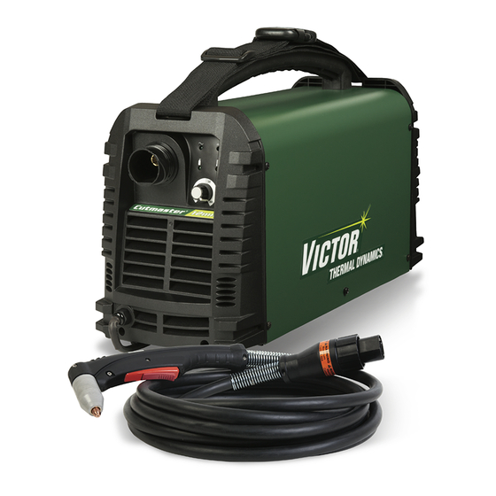
INTRODUCTION CUTMASTER 10MM, 12MM 2.06 Power Supply Features 240 VAC Power Source Air Inlet To Air Supply (clean/dry) Control Panel Art # A-10217 Torch Lead Work Cable and Clamp Figure 2-2- Power Supply Features On/Off Switch Air Inlet, 1/4” NPT... - Page 18 CUTMASTER 10MM, 12MM INTRODUCTION Notes Introduction Manual 0-5230...
-
Page 19: Section 2Torch: Introduction
INTRODUCTION cutmaster 10MM, 12MM SECTION 2TORCH: G. Current Ratings INTRODUCTION SL60 Current Ratings Up to 60 Amps, DC, SL60 Torch & Leads 2T.01 Scope of Manual Straight Polarity This manual contains descriptions, operating instructions and main- NOTE tenance procedures for the SL60 Plasma Cutting Torch. Service of Power Supply characteristics will determine material this equipment is restricted to properly trained personnel; unquali-... -
Page 20: 03 Introduction To Plasma
CUTMASTER 10MM, 12MM INTRODUCTION D. Main Cutting Arc 2T.03 Introduction to Plasma DC power is also used for the main cutting arc. The negative A. Plasma Gas Flow output is connected to the torch electrode through the torch lead. The positive output is connected to the workpiece via the Plasma is a gas which has been heated to an extremely high work cable and to the torch through a pilot wire. -
Page 21: Installation
Carry bag SL60 Torch (Including SL60 Torch 20 ft/6.2m w/ATC, consumables set, spare parts kit) Shoulder Strap Operating Manual Table 3-1- Contents List for CutMaster 10mm Plant B. Contents List for CutMaster 12mm Plant Part No. 1-4200-6 Description Quantity CM 12mm Power Source... -
Page 22: Air Supply Connections
CUTMASTER 10MM, 12MM INSTALLATION 3.03 Air Supply Connections A. Connecting Air Supply to Unit B. Using Industrial Compressed Air In Gas Cylinders The connection is the same for compressed air or in- dustrial compressed air in gas cylinders. When using industrial compressed air in gas cylinders as the gas supply: 1. -
Page 23: Power Source Specifications
CUTMASTER 10mm Power Source Specifications Input Power 240 VAC (+/-15%), 1 Phase, 50/60Hz Output Current 20-30 Amps @ 240VAC CUTMASTER 10mm Power Source Duty Cycle (Note 1) Ambient Temperature 104° F (40° C) Duty Cycle 40% @ 240VAC Rated Current 30 Amps @ 240VAC SL60 Torch Gas Requirements (See Section 2T.02) - Page 24 CUTMASTER 10MM, 12MM INSTALLATION 9" (228.6mm) 18.5" (469.9mm) Art # A-10216 7" (177mm) 26lb / 11.8kg Figure 3-3 - Power Source Dimensions & Weight NOTE Weight includes torch & leads, input power cord, and work cable with clamp. CAUTION Provide clearance for proper air flow through the Power Source. Operation without proper air flow will inhibit proper cooling and reduce duty cycle.
-
Page 25: Input Wiring Specifications
INSTALLATION CUTMASTER 10MM, 12MM 3.05 Input Wiring Specifications CUTMASTER 10mm Input Power Requirements Suggested Sizes (See Input Power Input Current Input Current Input Note) Voltage Frequency (kVA) Max (Amps) eff (Amps) Fuse (Amps) (Volts-AC) (Hz) 1-Ph 1-Ph 1-Ph 1-Ph 50/60 15.6... - Page 26 CUTMASTER 10MM, 12MM INSTALLATION Notes Installation Manual 0-5230...
-
Page 27: Section 4 System
OPERATION CUTMASTER 10MM, 12MM SECTION 4 SYSTEM: OPERATION 4.01 Control Panel On/O Air Inlet, Switch 1/4” NPT AC Indicator Power Cord DC Indicator (Ready) Air Indicator Overheat Indicator CUTMASTER 12mm ® Art # A-10218 Figure 4-1 - Front Control Panel Figure 4-2 - Rear Controls 1. -
Page 28: Preparations For Operating
CUTMASTER 10MM, 12MM OPERATION 4.02 Preparations for Operating At the start of each operating session: WARNING Disconnect primary power at the source before assembling or disassembling Power Source, torch parts, or torch and leads assemblies. NOTE All consumables must be correctly installed and maintained to ensure correct operation. - Page 29 OPERATION CUTMASTER 10MM, 12MM B. Torch Connection Check that the torch is properly connected. C. Check Primary Input Power Source 1. Check the power source for proper input voltage. Make sure the input power source meets the power requirements for the unit per Section 2, Specifications.
-
Page 30: Sequence Of Operation
CUTMASTER 10MM, 12MM OPERATION 4.03 Sequence of Operation The following is a typical sequence of operation for this Power Source. 1. Place the ON/OFF switch on the Power Source to ON (up) position. a. AC indicator turns ON; fan turns ON. - Page 31 OPERATION CUTMASTER 10MM, 12MM • Drag Cutting With a Hand Torch Trigger Drag cutting works best on metal 1/4" (6mm) thick or less. NOTE For best parts performance and life, always Trigger Release use the correct parts for the type of opera- tion.
-
Page 32: Cut Quality
CUTMASTER 10MM, 12MM OPERATION Bottom Dross Buildup 4.04 Cut Quality Molten material which is not blown out of the cut NOTE area and resolidifies on the plate. Excessive dross Cut quality depends heavily on setup and may require secondary cleanup operations after parameters such as torch standoff, align- cutting. -
Page 33: General Cutting Information
OPERATION CUTMASTER 10MM, 12MM 4.05 General Cutting Information Direction of Cut In the torches, the plasma gas stream swirls as it leaves the torch to maintain a smooth column of WARNING gas. This swirl effect results in one side of a cut being more square than the other. - Page 34 CUTMASTER 10MM, 12MM OPERATION Notes Operation Manual 0-5230...
-
Page 35: Theory Of Operation
THEORY OF OPERATION CUTMASTER 10MM, 12MM SECTION 5: THEORY OF OPERATION 5.01 Inverter Design What does the word inverter mean? The term inverter refers to the ability to change DC power into AC. Inverter power supplies immediately rectify the incoming AC to DC, and then the transistors create a higher frequency AC. The higher frequency AC then goes on to a much smaller main transformer than in a conventional power supply. - Page 36 CUTMASTER 10MM, 12MM THEORY OF OPERATION Notes Theory of Operation Manual 0-5230...
-
Page 37: Troubleshooting
TROUBLESHOOTING CUTMASTER 10MM, 12MM SECTION 6: TROUBLESHOOTING 6.01 Basic Troubleshooting-Power Source Faults WARNING There are extremely dangerous voltage and power levels present inside this unit. Do not attempt to diagnose or repair it un- less you are an accredited service provider and you have had training in power electronics measurement and troubleshooting techniques. - Page 38 CUTMASTER 10MM, 12MM TROUBLESHOOTING 2. Working cable connection is poor. F. No cutting output when torch is activated; AC indicator ON, gas flows, fan turns. Make sure that work cable has a proper connection to a clean, dry area of the work 1.
-
Page 39: Checking Unit Before Applying Power
TROUBLESHOOTING CUTMASTER 10MM, 12MM 2. Torch is being moved too fast across work piece Reduce cutting speed. 3. Excessive oil or moisture in torch Hold torch 1/8 inch (3 mm) from clean surface while purging and observe oil or moisture buildup (do not activate torch). -
Page 40: Case Removal
CUTMASTER 10MM, 12MM TROUBLESHOOTING 6.04 Case Removal WARNING Read and follow safety information in Section 6.02 before proceeding. Remove the ten screws from the case and remove the case panel. Art # A-10242 Figure 6-2 Case Removal View Troubleshooting Manual 0-5230... -
Page 41: Visually Inspect
TROUBLESHOOTING CUTMASTER 10MM, 12MM 6.05 Visually Inspect WARNING Read and follow safety information in Section 6.02 before proceeding. 1. Take out clear protective sheet over main inverter board. Art # A-10243 Figure 6-3 Clear Protective Sheet Removal View 2. Visually inspect the inside of the Power Source. The levels of current present in these units can cause burning or arcing of PCB, transformers, switches, or rectifier when a failure occurs. -
Page 42: Preliminary Check Of The Main Inverter Board
CUTMASTER 10MM, 12MM TROUBLESHOOTING 6.06 Preliminary Check of the Main Inverter Board WARNING Read and follow safety information in Section 6.02 before proceeding. Figure 6-4 Main Inverter Board Troubleshooting Manual 0-5230... - Page 43 TROUBLESHOOTING CUTMASTER 10MM, 12MM DC Bus Testing Multimeter Lead Placement Voltage with Supply voltage OFF Positive meter lead to TP 30 Upper capacitor bank 0 VDC Negative meter lead to TP 29 Positive meter lead to TP 32 Lower capacitor bank...
-
Page 44: Check Main On/ Off Switch
CUTMASTER 10MM, 12MM TROUBLESHOOTING 6.07 Check Main ON/ OFF Switch WARNING Read and follow safety information in Section 6.02 before proceeding. Art # A-10245 Figure 6-5 Main ON/ OFF Switch View Power Switch Testing Multimeter Lead Placement Impedance Switch ON Positive meter lead to TP 1 0 to 1 Ω... -
Page 45: Check Pressure Switch
TROUBLESHOOTING CUTMASTER 10MM, 12MM 6.08 Check Pressure Switch Art # A-10292 Figure 6-6 Pressure Switch View Turn ON the power switch, disconnect the contact of the pressure switch and start the test as below: 1. Pressure switch open When the pressure is up to 3.5kgf/cm (49.78 PSI), the pressure switch turns OFF. -
Page 46: Check Regulator
CUTMASTER 10MM, 12MM TROUBLESHOOTING 6.09 Check Regulator Art # A-10293 Figure 6-7- Regulator View Turn ON the power switch and start the test as below: When solenoid valve is ON,adjust the knob 1. If the pressure is continuously adjustable, the regulator is OK. Troubleshooting 6-10 Manual 0-5230... -
Page 47: Check Main Input Rectifier
TROUBLESHOOTING CUTMASTER 10MM, 12MM 6.10 Check Main Input Rectifier DC— Art # A-10291 Figure 6-8 Main Input Rectifier Remove the main input rectifier from the heatsink and start the testing. Input Rectifier Testing Multimeter Lead Placement Diode Voltage Positive meter lead to AC1 AC1 to DC+ 0.2 –... -
Page 48: Dc Bus Voltage Measurement
CUTMASTER 10MM, 12MM TROUBLESHOOTING 6.11 DC Bus Voltage Measurement Apply voltage to the Power Source. Warning There are extremely dangerous voltage and power levels present inside this Power Source. Do not attempt to diagnose or repair unless you have had training in power electronics measurement and troubleshooting techniques. -
Page 49: Check Of Control Pcb
TROUBLESHOOTING CUTMASTER 10MM, 12MM 6.12 Check of Control PCB WARNING Read and follow safety information in Section 6.02 before proceeding. Figure 6-9 Control PCB Manual 0-5230 6-13 Troubleshooting... - Page 50 CUTMASTER 10MM, 12MM TROUBLESHOOTING HF/QF Header Pin Pin function Signal 0VDC Control circuit power source 27VDC Negative of solenoid control signal 0VDC (when soleniod is on) Positive of solenoid control signal 27VDC Table 6-6 HF/QF Header Pin Function MB Header Pin...
- Page 51 TROUBLESHOOTING CUTMASTER 10MM, 12MM WA Header Pin Pin function Signal Power source of current sensor 15VDC Power source of current sensor -15VDC Output current feedback 0VDC Table 6-12 WA Header Pin Function FAN Header Pin Pin function Signal Power source of fan...
-
Page 52: Waveforms
CUTMASTER 10MM, 12MM TROUBLESHOOTING 6.13 Waveforms NOTE All waveforms below are taken with ISOLATED oscilloscope probes. These parts being measured are MAINS potential. An isolating transformer should be used for the oscilloscope, or isolated probes should be used. If an isolating transformer is used, the frame of the oscilloscope may be live, and suitable care should be taken to avoid electric shock. -
Page 53: Main Circuit Description
TROUBLESHOOTING CUTMASTER 10MM, 12MM 2. Vds of inverter IGBT at full load TP C1: 4 and 5 C2: 9 and 10 (Testpoints refer to main inverter board in Sec. 6.06 ). Timebase Trigger Stop Positive Art # A-10248 6.14 Main Circuit Description WARNING Turn off power and disconnect mains supply plug from receptacle before working on the unit. - Page 54 CUTMASTER 10MM, 12MM TROUBLESHOOTING PFC Control Chip Art # A-10249 Figure 6-10 Main Circuit Description Troubleshooting 6-18 Manual 0-5230...
- Page 55 TROUBLESHOOTING CUTMASTER 10MM, 12MM The mains supply voltage is connected via a double pole switch to the input rectifier U1 through an EMC filter. Overvoltage protection is provided by varistor CY1. The rectifier circuit converts the inputted AC voltage to DC voltage. The input current is controlled through being compared with reference wave.
-
Page 56: Circuit Diagram
CUTMASTER 10MM, 12MM TROUBLESHOOTING 6.15 Circuit Diagram Art # A-11638 Figure 6-11 Circuit Diagram Troubleshooting 6-20 Manual 0-5230... -
Page 57: Section 6 Torch
CUTMASTER 10MM, 12MM SECTION 6 TORCH: SERVICE 6T.01 General Maintenance Cleaning Torch Even if precautions are taken to use only clean air with a torch, eventually the inside of the torch Upper Groove becomes coated with residue. This buildup can... -
Page 58: 02 Inspection And Replacement Of Consumable Torch Parts
CUTMASTER 10MM, 12MM 6T.02 Inspection and Replacement of Consumable Torch Parts 3. Remove the tip. Check for excessive wear (in- dicated by an elongated or oversized orifice). Clean or replace the tip if necessary. WARNING Worn Tip Good Tip Disconnect primary power to the system be- fore disassembling the torch or torch leads. -
Page 59: Disassembly Procedure
DISASSEMBLY PROCEDURE CUTMASTER 10MM, 12MM SECTION 7: DISASSEMBLY PROCEDURE 7.01 Safety Precautions for Disassembly WARNING Read and follow safety information in Section 6.02 before proceeding. Unplug unit before beginning Disassembly procedure. Manual 0-5230 Disassembly Procedure... -
Page 60: Control Pcb Removal
CUTMASTER 10MM, 12MM DISASSEMBLY PROCEDURE 7.02 Control PCB Removal WARNING Read and follow safety information in Section 6.02 before proceeding the disassembly. Remove case (refer to 6.04) before removing control PCB. Refer to graphics on page 7-3. 1. M4 Screw. Remove 4 screws from Control panel. -
Page 61: Front Panel Assembly Removal
DISASSEMBLY PROCEDURE CUTMASTER 10MM, 12MM 7.03 Front Panel Assembly Removal WARNING Read and follow safety information in Section 6.02 before proceeding the disassembly. 1. Unscrew the ten screws from the case panel and remove it. 2. Unscrew the two screws on front panel 3. -
Page 62: Front Panel (Operator Interface) Pcb Removal
CUTMASTER 10MM, 12MM DISASSEMBLY PROCEDURE 7.04 Front Panel (Operator Interface) PCB Removal WARNING Read and follow safety information in Section 6.02 before proceeding the disassembly. 1. Remove the screw on the potentiometer knob. 2. Remove the nut. 3. Remove the front PCB. -
Page 63: Rear Panel Removal
DISASSEMBLY PROCEDURE CUTMASTER 10MM, 12MM 7.05 Rear Panel Removal WARNING Read and follow safety information in Section 6.02 before proceeding the disassembly. 1. Remove screws on rear panel. 2. Remove the three screws. 3. Terminals from supply cable. Disconnect two terminals from switch. -
Page 64: Power Switch S1 And Power Cord Removal
CUTMASTER 10MM, 12MM DISASSEMBLY PROCEDURE 7.06 Power Switch S1 and Power Cord Removal WARNING Read and follow safety information in Section 6.02 before proceeding the disassembly. 1. Gas inlet. Remove gas inlet from rear panel. 2. SW locking tabs Squeeze the locking tabs and push SW out from the rear panel. -
Page 65: Base Panel Removal
DISASSEMBLY PROCEDURE CUTMASTER 10MM, 12MM 7.07 Base Panel Removal WARNING Read and follow safety information in Section 6.02 before proceeding the disassembly. 1. Remove central panel screws. 2. Remove main power PCB assembly screws. Art # A-11086 Figure 7-6 Removing Base Panel... - Page 66 CUTMASTER 10MM, 12MM DISASSEMBLY PROCEDURE Notes Disassembly Procedure Manual 0-5230...
-
Page 67: Assembly Procedures
ASSEMBLY PROCEDURE CUTMASTER 10MM, 12MM SECTION 8: ASSEMBLY PROCEDURES 8.01 Installing Base Board 1. Place main power PCB assembly 2. Install main power PCB assembly screws 3. Install central Panel Screws. Art # A-11087 Figure 8-1 Installing Base Board Manual 0-5230... -
Page 68: Installing Rear Panel
CUTMASTER 10MM, 12MM ASSEMBLY PROCEDURES 8.02 Installing Rear Panel 1. Install gas inlet. 2. Install ON/OFF switch 3. Install wire cord. 4. Reconnect Input Wire on the ON/OFF switch. 5. Install fan. 6. Install ground wire. 7. Reconnect AC Input wire on Main Power PCB to power ON/OFF switch. - Page 69 ASSEMBLY PROCEDURE CUTMASTER 10MM, 12MM Art # A-10258 Figure 8-2 Installing Rear Panel Manual 0-5230 Assembly Procedures...
-
Page 70: Installing Front Panel
CUTMASTER 10MM, 12MM ASSEMBLY PROCEDURES 8.03 Installing Front Panel 1. Place front panel PCB assembly into front panel. Install the nut and screw. 2. Reconnect three harnesses to control PCB. 3. Reconnect two red wires and install the screws. 4. Install the front panel screws. -
Page 71: Installing Main Control Pcb And Clear Cover Sheet
ASSEMBLY PROCEDURE CUTMASTER 10MM, 12MM 8.04 Installing Main Control PCB and Clear Cover Sheet 1. Install 4 screws. 2. Plug harness into HF/QF connector 3. Plug harness into MB connector 4. Plug harness into SOURCE&TIP connector 5. Plug harness into DRIVE connector 6. - Page 72 CUTMASTER 10MM, 12MM ASSEMBLY PROCEDURES Art # A-10250 Art # A-10260 Figure 8-4 Installing Main Control PCB and Clear Cover Sheet Please refer to Figure 6-9 in Section 6.12 for control PCB. Assembly Procedures Manual 0-5230...
-
Page 73: Installing Case
ASSEMBLY PROCEDURE CUTMASTER 10MM, 12MM 8.05 Installing Case 1. Install Case. 2. Install the ten screws and tighten them. Art # A-10261 Figure 8-5 Installing the Case Manual 0-5230 Assembly Procedures... - Page 74 CUTMASTER 10MM, 12MM ASSEMBLY PROCEDURES Notes Assembly Procedures Manual 0-5230...
-
Page 75: Replacement Parts
REPLACEMENT PARTS CUTMASTER 10MM, 12MM SECTION 9: REPLACEMENT PARTS 9.01 Introduction A. Parts List Breakdown C. Ordering Information Order replacement parts by part number and The parts list provides a breakdown of all replace- complete description of the part or assembly, as able components. -
Page 76: Sl60 Replacement Parts
CUTMASTER 10MM, 12MM REPLACEMENT PARTS 9.03 SL60 Replacement Parts Item # Description Part No Electrode, 30-120 Amp OTD9/8215 Start Cartridge OTD9/8213 Tip, 40A Drag (fitted) OTD9/8207 Tip, 40A Standoff OTD9/8208 Shield Cup OTD9/8218 SL60 Torch w/20 ft (6,2m) leads (not shown) -
Page 77: Statement Of Warranty
Victor Technologies will repair or replace, at its discretion, any warranted parts or components that fail due to defects in material or workmanship within the time periods set out below. Victor Technologies must be notified within 30 days of any failure, at which time Victor Technologies will provide instructions on the warranty procedures to be implemented. -
Page 79: Global Customer Service Contact Information
China Fax: 61-3-9474-7391 Telephone: 86-21-64072626 Email: [email protected] Fax: 86-21-64483032 Victor Technologies USA Victor Technologies Asia Sdn Bhd 2800 Airport Road Lot 151, Jalan Industri 3/5A Denton, Tx 76207 USA Rawang Integrated Industrial Park - Jln Batu Arang Telephone: (940) 566-2000... - Page 80 Asia Pacific Regional Headquarters 71 Gower Street Preston, Victoria, Australia, 3072 Telephone: +61 3 9474 7400 FAX: +61 3 9474 7391 Email: [email protected] www.victortechnologies.com...