Table of Contents
A Better Built Machine.
Owner's Manual
READ THIS MANUAL CAREFULLY,
IT CONTAINS IMPORTANT SAFETY INFORMATION.
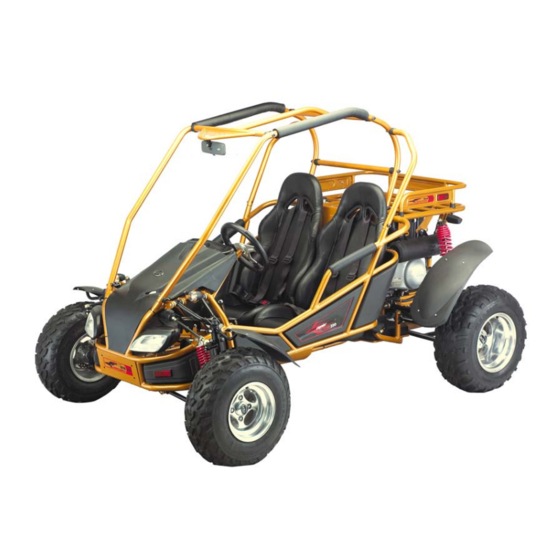
INTERCEPTOR GTR 250/300
This kart is designed for off-road use only
and does not comply with Federal Motor Vehicle Safety Standards.
Recommended for Ages 16+
C-GTR-2861-DIFFERENTIAL-US-05-2007
MODEL:2861-
Differential
Chapters
Table of Contents

Related Manuals for Carter INTERCEPTOR GTR 250

Summary of Contents for Carter INTERCEPTOR GTR 250
- Page 1 A Better Built Machine. Owner’s Manual READ THIS MANUAL CAREFULLY, IT CONTAINS IMPORTANT SAFETY INFORMATION. INTERCEPTOR GTR 250/300 MODEL:2861- Differential This kart is designed for off-road use only and does not comply with Federal Motor Vehicle Safety Standards. Recommended for Ages 16+...
-
Page 3: Carter Brothers Manufacturing, Co. , Inc
Failure to follow the warnings contained in this manual could result in serious injury or death. The Interceptor GTR 250 fits the needs of a wide variety of kart users above 16 years old. Beginners should seek instruction from your dealer or qualified instructors before and during intial use of the kart. -
Page 4: Table Of Contents
INDEX Owner’s Manual Warranty About Safety Important Safety Information Safety Labels AreYou Ready To Drive? Is Y our Vehicle Ready T o Drive? Safe Driving Precautions General Informations Specifications Locations Of Parts Operation Periodic Checks And Services Service Instructions Service Information Wiring Diagram Trouble Shooting Charts Set-up Instructions... -
Page 5: Warranty
To register your product, complete the Warranty Registration form. Fax or mail the warranty registration form with a copy of the sales receipt to Carter. A warranty registration form be on file with Carter before a warranty claim can be processed. - Page 6 WARRANTY COVERAGE Carter Brothers Manufacturing, Inc. will repair or replace, at its option, any part that is found defective in material or factory workmanship under normal use.
- Page 7 We do not charge for parts for authorized warranty repairs. Any defective parts from repairs are required to be returned to Carter upon request. All warranties are voided if the vehicle has been altered for use in racing or competition, rented, used under abnormal conditions, or subject to abuse, misuse, neglect or improper maintenance.
- Page 8 A Better Built Machine. W arranty registration must be filed with Carter Brothers Manufacturing within 10 days of purchase or warranty will be void. In order to validate the warranty, purchaser agrees and promises to hold Carter Brothers Manufacturing and the Dealer harmless...
-
Page 9: About Safety
ABOUT SAFETY In order to keep everyone safe, you must take responsibility for the safe operation of your kart. To help you make informed decisions about safety, we have provided operating procedures and other information on labels and in this manual. This information alerts you to potential hazards that could hurt you or others. -
Page 10: Important Safety Information
IMPORTANT SAFETY INFORMATION Your kart will provide you with many years of service and pleasure, providing you take responsibility for your own safety and understand the challenges you may meet while driving. There is much that you can do to protect yourself while operating your kart. You'll find many helpful recommendations throughout this manual. - Page 11 IMPORTANT SAFETY INFORMATION Drive within Your Limits Pushing limits is another major cause of kart accidents. Never drive beyond your personal abilities or faster than conditions warrant. Remember that alcohol, drugs, fatigue, and inattention can significantly reduce your ability to make good judgments and drive safely.
-
Page 13: Areyou Ready To Drive
ARE YOU READY TO DRIVE ? Before each drive, make sure you and your kart are both ready to drive. This section discusses how to evaluate your driving readiness, what items you should check on your kart, and adjustments to make for your comfort, convenience, or safety. Before you drive your kart for the first time, we urge you to: Read this owner's manual and the labels on your kart carefully. -
Page 14: Are You Ready To Drive
ARE YOU READY TO DRIVE? Additional Driving Gear In addition to a helmet and eye protection, we also recommend: Sturdy off-road motorcycle boots to help protect your feet, ankles, and lower legs. Off-road motorcycle gloves to help protect your hands. Driving pants with knee and hip pads, a driving jersey with padded elbows, and a chest/ shoulder protector. -
Page 15: Is Y Our Vehicle Ready T O Drive
IS YOUR VEHICLE READY TO DRIVE? Before each drive, it is important to inspect your kart and make sure any problems you find are corrected. A pre-drive inspection is a must, not only for safety, but because having a breakdown, or even a flat tire, can be a major inconvenience. If your kart has overturned or has been involved in a collision, do not drive it until your kart has been inspected by your dealer. -
Page 16: Is Your Vehicle Ready To Drive
IS YOUR VEHICLE READY TO DRIVE? Leaks, Loose Parts Walk around your kart and look for anything that appears unusual, such as a leak or loose cable. Lights Make sure the headlights, brake light, and tail light are working properly. Throttle Check the freeplay and adjust if needed. -
Page 17: Safe Driving Precautions
SAFE DRIVING PRECAUTIONS Off-Road Use Only Your kart and its tires are designed and manufactured for off-road use only, not for pavement. Driving on pavement can affect handling and control. You should not drive your kart on pavement. WARNING Operating this kart on paved surfaces may seriously affect handling and control of the kart, and may cause the vehicle to go out of control. - Page 18 SAFE DRIVING PRECAUTIONS Control Speed Driving at excessive speeds increases the chance of an accident. In choosing a proper speed, you need to consider the capability of your kart, the terrain, visibility and other operating conditions, plus your own skills and experience. WARNING Operating this kart at excessive speeds increases your chances of losing control of the kart, which can result in an accident.
-
Page 19: General Information
GENERAL INFORMATION MODEL IDENTIFICATION FRAME NUMBER The frame number or VIN is stamped on the upper firewall of the frame behind the seat. VIN NUMBER LOCATION ENGINE NUMBER The engine number is located on the lower front left side of the engine case. FUEL RECOMMENDATIONS FUEL Gasoline should be 92 octane or higher. -
Page 20: Specifications
SPECIFICATIONS DIMENSIONS Overall Length ---------------------------------------------------------------------------- 92 in. (2340mm) Overall Width ---------------------------------------------------------------------------- 64 in. (1620mm) Overall Height ----------------------------------------------------------------------------- 61 in. (1541mm) Wheelbase ---------------------------------------------------------------------------------- 68 in. (1727mm) Front Track ------------------------------------------------------------------------------ 47.1 in. (1060mm) Rear Track ------------------------------------------------------------------------------- 39.4 in. (1000mm) Ground Clearance ---------------------------------------------------------------------------- 8 in. (205mm) ENGINE Type -------------------------------------------------------------------------------------------------- 4-Stroke Engine Capacity --------------------------------------------------------------------------------------- 250cc... - Page 21 SPECIFICATIONS CHASSIS Front, Rear Brake ----------------------------------------------------------------------------- Hydraulic disc Front Tire -----------------------------------------------------------------------------------------23x7-10 14psi Rear Tire ------------------------------------------------------------------------------------------25x10-12 14psi Front Suspension ---------------------------------------------------------------------------------Dual A-Arm Rear Suspension ---------------------------------------------------------------------------------Dual A-Arm Restraint System --------------------------------------------------------------------- Dual 4-point Harness Final Drive Chain -------------------------------------------------------------------------------- 520 x 66 WEIGHT Net Weight -----------------------------------------------------------------------------------------345kgs/761lbs *The specifications are subject to change without notice.
-
Page 22: Location Of Parts
LOCATION OF PARTS MIRROR SEAT BELT STEERING WHEEL HEADLIGHTS R.R. WHEEL FR. WHEEL REAR CARGO RACK TOW BALL DRIVE CHAIN... - Page 23 LOCATION OF PARTS KEY SWITCH ENGINE STOP BUTTON HEADLIGHT SWITCH BLINKER HORN 12V OUTLET REAR CARGO RACK RADIATOR ENGINE FUEL TANK...
-
Page 24: Operation
OPERATION A. Operation Controls WARNING - Do not attempt to start or operate the engine until you are completely familiar with the location and use of each control necessary to operate this vehicle. The operator must know how to stop this machine before starting and driving it. a. - Page 25 OPERATION B. Pre-Drive Inspection WARNING Perform this pre-drive inspection everyday before driving vehicle. If not performed, serious damage to the vehicle or personal injury may result. a. Check engine oil level. Check for leaks, add oil if required. b. Check fuel level. Add fuel as necessary and do not overfill. Check for leaks. c.
- Page 26 OPERATION C. Passengers The vehicle allows for two riders only. Combined maximum weight of driver and the passenger should not exceed 180kg or 400lbs. D. Seat Adjustment The seat must always be securely fastened in the position which best affords the operator control of the foot pedals, steering wheel, and the remote stop button.
- Page 27 OPERATION YOKE F. Gear Shift Lever YOKE ADJUSTMENT a. Each end of the cable has a threaded yoke on it. b. You must remove the pin or bolt in either end of the cable to which the yoke is attatched. c.
-
Page 28: Starting
OPERATION G. Starting And Operating Instructions a. Before starting the engine, be sure that the driver is seated properly in the kart with the seat belt fastened. b. Test the kart in an open space at the beginning to learn how to start, turn, and stop. c. -
Page 29: Ignition
PERIODIC CHECK AND SERVICES Have your kart checked, adjusted, and record maintenance performed.Have these services performed periodically by your Carter Authorized Dealer to maintain the kart at the optimum condition. Every 300km 1 Month 3 Months 6 Months 1 Year... -
Page 30: Service Instructions
SERVICE INSTRUCTIONS Torque Values The torque values listed in this table are for more important tightened torque values. Please see standard values for torques not listed in the table. Torque Tightening Char Kg.m Ib-ft Kg.m Ib-ft Diameter 1 ~2 0.1 ~0.2 0.7 ~1.5 1.5 ~3 0.15 ~0.3... - Page 31 SERVICE INSTRUCTIONS B. Engine Lubrication You must change the oil in the crankcase after the first 5 hours of operating your new engine and after 10 hours of use thereafter. This will insure proper lubrication of internal parts and prevent costly repairs due to excessive wear. WARNING Used oil must be disposed of at a proper collection center.
-
Page 32: Spark Plug
SERVICE INSTRUCTIONS D. Carburetor Adjustment Never make unnecessary adjustments. The factory recommended settings are correct for most applications. WARNING Air screw was set at factory, so no adjustment is needed. Note the number of turns it takes to scew it all the way in for ease of installation. The parking brake must be used to stop the kart to perform the adjustments. - Page 33 SERVICE INSTRUCTIONS F. Cleaning Instructions Keep your kart clean. With clean rag, wipe off dirt and oil from around controls. Wipe off any spilled fuel and oil. Keep the engine clean of foreign objects, and be sure to check that air intake fan is free of debris for proper cooling.
- Page 34 SERVICE INSTRUCTIONS H. Adjustment of Front and Rear Shocks There are five adjustable positions on each shock. The default position is in the middle. a.Use a round nut wrench to adjust the shock. b.The tension of the shock spring will increase as you scew to the right.
-
Page 35: Service Information
SERVICE INFORMATION J. Front Wheel Replacement Do not disassemble the castle nuts when you replace the front wheels. It is only necessary to remove the four 4 lug nuts to remove the wheel. Tighten the nuts after replacing the wheels. Figure 7 Figure 7 Figure 11... - Page 36 SERVICE INFORMATION L. Front Wheel Alignment a. The front wheels should be “toe-in” from 1/8” to 1/4”. To check for alignment, measure distance A and B between the centerline (CL) of the wheels. The proper toe-in dimension A should be 1/8” – 1/4” greater than dimension B. b.
- Page 37 SERVICE INFORMATION M. Fuel Switch (Petcock) This vehicle has a manually operated fuel petcock with three positions. Please follow maintenance procedures accordingly. a. Periodically clean the petcock externally with grease remover and water. b. Check for any leaks or seeping fuel. “ON”...
- Page 38 SERVICE INFORMATION O. Steering Shaft a. Remove the nuts from steering block. G rease inside of steer-block periodically. Needle Bearing Steering Column b. Loosen steering shaft, clamp nut and steering gear box. Steering Shaft Link Steering Gear Box Clamp Nut c.
- Page 39 SERVICE INFORMATION P. Steering Gear Box and Ball HEAD AND STEERING GEAR BOX a. Remove four bolts on LH and RH clamp nut b. Remove and check ball head dust cover and and steering gear box. steering gear box for wear. Ball Head Dust Cover Steering Gear Box Bolts and Nuts...
- Page 40 SERVICE INFORMATION Q. Steering Knuckle Support a. Remove rubber dust cover of the knuckle support. Ball Head Dust Cover b. Check the grease of ball joint. Clean it if it is dirty and fill with grease. Filled With Grease c. Replace the steering knuckle support if the ball joint is loose or steering isn’t flexible. Steering Knuckle Support Spindle Ball Joint...
- Page 41 SERVICE INFORMATION R. Throttle and Brake Pedal a. Remove throttle, throttle pedal and axle nut, check for signs of wear. Replace if wear is present. b. Fill with grease in order to make the throttle and brake pedal swing more flexibly before installation. S.
- Page 42 SERVICE INFORMATION V. Radiator WARNING While engine is running, never attempt to open the radiator filler cap. The pressurized hot coolant may shoot out and cause serious scalding injury. No maintenance work is allowed to be performed unless the engine is completely cooled down. a.
- Page 43 SERVICE INFORMATION X. Front Hubs a. Check seals for rips or tears and replace if any exist. b. Inspect bearings for ease of movement. If bearings are dirty or muddy, wash them in cleaning solvent and spin with your finger. Never spin them vith compressed. c.
-
Page 44: Wiring Diagram
WIRING DIAGRAM Red/White White/Red Yellow/Red Blue/White White/Black... -
Page 45: Trouble Shooting Charts
TROUBLE SHOOTING CHARTS A. Engine hard to start or can not be started. Check and Adjustment Fault Condition Probable Causes Loosen carburetor drain bolt to check if there is gasoline inside No fuel in fuel tank. the carburetor. Check if the pipes, fuel tank to carburetor, and intake vacuum, are clogged. - Page 46 TROUBLE SHOOTING CHARTS B. Engine Runs Sluggish (Speed does not pick up, lack of power). Check and Adjustment Fault Condition Probable Causes Try gradual acceleration and check engine speed. Air cleaner clogged. Poor fuel supply. Engine speed can be Engine speed can not be Lines in fuel tank evaporation system increased.
- Page 47 TROUBLE SHOOTING CHARTS C. Engine Runs Sluggish (especially in low speed and idling) Check and Adjustment Fault Condition Probable Causes Check ignition timing (using ignition lamp). Abnormal Normal Incorrect ignition timing (malfunction of CDI or AC alternator). Adjust the air screw of carburetor.
- Page 48 TROUBLE SHOOTING CHARTS E. Clutch, Driving and Driving Pulley Probable Causes Fault Conditions Drive belt worn out or deformed. Ramp plate of movable drive face damaged. Engine can be started but Driving pulley spring broken. kart can not be moved. Clutch weights broken.
- Page 49 TROUBLE SHOOTING CHARTS G. Lose Power Check and Adjustment Fault Condition Probable Causes Raise wheels off ground and spin by hand. Brake dragging. Spin freely. Abnormal Drive chain too tight. Damaged wheel bearing. Wheel bearing needs lubrication. Check tire pressure. Normal.
-
Page 50: Set-Up Instructions
SET-UP INSTRUCTIONS INTERCEPTOR GTR 250 TOOLS NEEDED Floor jack Flat head screw driver Needle nose pliers Phillips head screw driver Protective gloves Adjustable wrench Metric wrench and socket set LIFT THE KART In order to assemble the front suspension and steering the unit must be lifted high enough to put the front tires on it. - Page 51 SET-UP INSTRUCTIONS INTERCEPTOR GTR 250 STEERING LINKAGE a. Attach each tie-rod end to the struts by inserting the ball joint studs into the steering arm of each strut. b. On each stud place flat washer, lock washer, tighten with 17mm wrench and lock with cotter pin and needle nose pliers.
- Page 52 SET-UP INSTRUCTIONS INTERCEPTOR GTR 250 CV SHAFT a. Slide the female end of each CV shaft over the male end of each side of the center axle. b. Lock into place with lock ring. The lock ring should already be in place on each end of the center axle.
- Page 53 SET-UP INSTRUCTIONS INTERCEPTOR GTR 250 STUMP GUARD AND TRAILER HITCH a. Place the stump guard under the rear suspension box/ under the rear sprocket. b. Align the 4 holes of the stump guard with the holes on the frame. c. Be sure all bolts are in place then tighten with 10mm and 12mm wrench.
- Page 54 SET-UP INSTRUCTIONS INTERCEPTOR GTR 250 REAR FENDERS a. Behind each seat is a mounting post for the rear fenders. b. Align the holes and slots of the fender bracket with those of the mounting post. c. Tighten with 10mm wrench.
- Page 55 SET-UP INSTRUCTIONS INTERCEPTOR GTR 250 BRUSH BARS a. Place the main bars in proper location by inserting the open ends over the bar mount posts on the frame. The bar mounting posts for the main bars are at the hood and behind the seat.
-
Page 56: Engine Oil
SET-UP INSTRUCTIONS INTERCEPTOR GTR 250 BATTERY a. Put on protective gloves b. Remove red strip covering acid ports from battery. c. Place funnel into acid ports on battery. Press acid container firmly into funnel allowing acid to flow into battery. - Page 57 SET-UP INSTRUCTIONS INTERCEPTOR GTR 250 FILL ING THE COOLING SYSTEM WITH COOLANT It is very important that you do not just fill the radiator and reservoir with coolant and begin to ride the unit. The cooling system MUST have all the air bled from it or the system will not cool the engine.
- Page 59 Carter Brothers Manufacturing, Co. , Inc. 1871 U.S. Highway 231 South Brundidge, Alabama 36010 Phone: 800-523-5278 A Better Built Machine www.carterbro.com...
-
Page 60: Parts Manual
A Better Built Machine. Parts Manual INTERCEPTOR GTR 250 MODEL:2861- Differential This kart is designed for off-road use only and does not comply with Federal Motor Vehicle Safety Standards. Recommended for Ages 16+ C-GTR-2861-DIFFERENTIAL-US-05-28-2007... - Page 62 GTR 250 PARTS MANUAL INDEX TO ENGINEER GROUP Head Cover ------------------------------------------------------------------- Fig.1 Cylinder Head Comp ------------------------------------------------------- Fig.2 Cylinder Assembly ---------------------------------------------------------- Fig.3 L Cover Assembly ----------------------------------------------------------- Fig.4 L Crank Case ----------------------------------------------------------------- Fig.5 R Crank Case ---------------------------------------------------------------- Fig.6 R Case Cover ---------------------------------------------------------------- Fig.7 Movable Drive Face --------------------------------------------------------- Fig.8...
-
Page 64: Head Cover
FIG.1 HEAD COVER Fig.1 HEAD COVER REF. DESCRIPTION PART NO. 8240-3107 Head Cover Gasket 8213-3001 Head Cover 8213-3002 Head Cover Assy. 8213-3003 Reed Valve Comp 8200-3190 Head Cover Bolt 8100-0161 Flange Bolt SH 6x16... -
Page 65: Cylinder Head Comp
FIG.2 CYLINDER HEAD COMP... - Page 66 GTR 250 PARTS MANUAL Fig.2 CYLINDER HEAD COMP REF. DESCRIPTION PARTS NO. Cylinder Head Comp. 8213-3004 Valve Stem Seal 8213-2002 Cam Shaft 8213-3005 In Valve Rocker Arm 8213-3006 In Valve Rocker Arm Assy. 8213-3007 EX. Valve Rocker Arm 8213-3008 EX. Valve Rocker Arm Assy. 8213-3009 Rocker Arm Shaft 8213-3010...
-
Page 67: Cylinder Assembly
FIG.3 CYLINDER ASSEMBLY Fig.3 CYLINDER ASSEMBLY REF. PART NO. DESCRIPTION 8213-3019 Cylinder Comp 8213-3020 Cylinder Assy. 8240-3105 Cylinder Gasket 8213-3021 Cam Chain Tensioner 8213-3022 Tensioner Lifter Assy. 8200-3191 Adjuster Bolt-cylinder 8240-3108 Tensioner Lifter Gasket 8200-3606 O-Ring H6T 8257-3013 Adjuster Spring-cylinder 8213-0035 Cam Chain Tensionerpivot 8213-3023... -
Page 68: L Cover Assembly
FIG.4 L COVER ASSEMBLY Fig.4 L COVER ASSEMBLY DESCRIPTION PART NO. REF. 8213-3024 L Cover 8213-3025 L Cover Plate 8240-3102 L Cover Plate Gasket 8213-3026 L Bearing Setting Plate 8213-3027 L Cover Assy. 8213-3028 Bearing Stay Collar 8213-3029 Bearing Stay Collar Assy. 8240-3104 L Cover Gasket 8200-3602... -
Page 69: L Crank Case
FIG.5 L CRANK CASE Fig.5 L CRANK CASE REF. DESCRIPTION PART NO. L Crank Case Comp 8213-3030 Setting Plate 8213-3031 Mission Breather Tube 8240-3201 Drain Tube Assy. 8213-3032 Tube Clip-E5 8213-3033 Change SW. Assy. 8213-3034 Cylinder Stud Bolt B 8200-3193 Spring, Fixed Catch 8257-3014 Screw, Fixing... -
Page 70: R Crank Case
FIG.6 R CRANK CASE Fig.6 R CRANK CASE DESCRIPTION REF. PART NO. 8213-3120 R Crank Case Comp 8213-3121 Wave Washer-E06 8240-3101 Crank Case Gasket 8213-3036 Cam Chain Setting Plate 8213-3037 Star. Reduction Gear Comp 8213-3038 Sta. Reduction Gear Shaft 8213-3039 Start Motor Assy. - Page 71 FIG.7 R CASE COVER...
-
Page 72: R Case Cover
GTR 250 PARTS MANUAL Fig.7 R CASE COVER REF. DESCRIPTION PARTS NO. 8213-3040 R Case Cover Comp 8213-3041 Clamp-E7 8213-0040 Tappet Adj Hole Cap Assy. 8213-0041 Oil Filter Screen 8257-0011 Oil Filter Screw Spring 8213-3042 Oil Level Gauge Assy. 8213-0050 Water Pump Impeller 8213-3043 Mechaniacl Seal... -
Page 73: Movable Drive Face
FIG.8 MOVABLE DRIVE FACE Fig.8 MOVABLE DRIVE FACE REF. PART NO. DESCRIPTION Slide Piece Set 8213-3047 Ramp Plate 8213-3048 Weight Roller Set (6pes/set) 8213-3049 Movable Drive Face Comp. 8213-3050 Drive Face Boss 8213-3051 Movable Drive Face Assy. 8213-3052 Drive Face 8213-3053 Thrust Washer 14x28x2 8200-0551... -
Page 74: Crank Shaft
FIG.9 CRANK SHAFT Fig.9 CRANK SHAFT DESCRIPTION REF. PART NO. Crank Shaft Comp 8213-3054 Piston Ring Set 8213-3055 Piston 8213-3056 Piston Pin 8213-3057 Connecting Rod 8213-3058 Conn. Rod Assy. 8213-3059 Balance Shaft Drive Gear 8213-3060 R Crank Side Plate 8213-3061 Crank Pin 8213-3062 Piston Pin Clip 17mm... -
Page 75: Ac Gen Flywheel
FIG.10 AC GEN FLYWHEEL Fig.10 AC GEN FLYWHEEL DESCRIPTION PART NO. REF. R Cover Gasket 8240-3103 Starting Clutch Gear Comp 8213-3064 One Way Clutch Assy. 8213-3065 AC Gen Flywheel Set 8213-3066 Flywheel Comp. 8213-3067 Stator Comp 8213-3068 Flange Nut 14mm 8200-0214 Thrust Washer 14x28x2 8200-0551... -
Page 76: Balance Shaft
FIG.11 BALANCE SHAFT Fig.11 BALANCE SHAFT REF. DESCRIPTION PART NO. 8213-3069 Balance Shaft Comp 8213-3070 Balance Shaft 8200-3511 Wave Washer 28.3x36x1 8213-3071 Balance Shaft Drive Gear A 8213-3072 Balance Shaft Drive Gear B 8257-3015 Balance Shaft Drive Gear Spring 8200-3505 Washer 28.3x47.5x1.4 8200-3504 Washer 28.3x36x1... -
Page 77: Mission Case
FIG.12 MISSION CASE... - Page 78 GTR 250 PARTS MANUAL Fig.12 MISSION CASE PARTS NO. REF. DESCRIPTION 8213-3073 Mission Case 8213-3074 Inner Cover Stay A 8240-3111 Mission Case Gasket 8213-3075 Drive shaftt 8213-3076 Counter Shaft Assy. 8213-3077 Counter Shaft 8213-3078 Counter Gear A 8213-3079 Counter Gear B 8213-3080 Bush 20x13 8213-3081...
-
Page 79: Oil Pump Assembly
FIG.13 OIL PUMP ASSEMBLY Fig.13 OIL PUMP ASSEMBLY DESCRIPTION PART NO. REF. 8213-3093 Oil Pump Assy. 8223-3002 Oil Pump Driven Sprocket 8231-3011 Oil Pump Chain 48L 8200-3605 Roller 2.5x11.8 8200-3402 Pan Screw 6X25 8200-0801 Circlip EX 10... - Page 80 Fig.14 CYLINDER HEAD SIDE COVER ASSEMBLY Fig.14 CYLINDER HEAD SIDE COVER ASSEMBLY DESCRIPTION REF. PARTS NO. Cyl. Head Side Cover Assy. 8213-3094 Breather Tube 8213-3095 Cam Sprocket 8223-0001 Cam Sprocket Washer 8200-0590 Centrifugal Disk 8213-0029 Cam Chain 100L 8231-3012 Lock Bolt 6mm 8200-0196 Flange Bolt SH 6x18 8100-0162...
-
Page 81: Driven Pully Set
Fig.15 DRIVEN PULLEY SET... - Page 82 GTR 250 PARTS MANUAL Fig.15 DRIVEN PULLEY SET REF. DESCRIPTION PARTS NO. Outer Clutch Comp 8213-3096 Drive Plate Assy. 8213-3097 Drive Plate Comp. 8213-3098 Clutch Side Plate 8213-3099 Clutch Spring 8257-3017 Clutch Weight (3pes/set) 8213-3100 Clutch Damper Rubber 8213-3101 Driven Pulley Assy. 8213-3102 Drive Belt 8238-3000...
- Page 83 FIG.16 A. I. C. V. ASSEMBLEY Fig.16 A. I. C. V. ASSEMBLEY PART NO. REF. DESCRIPTION A.I.C.V. Unit 8213-3110 A.I.C.V. Assy. 8213-3111 A.I.C.V. Inlet Pipe Joint Tube Assy. 8213-3112 A.I.A.C Setting Band 8213-0117...
-
Page 84: Carburetor Assembly
FIG.17 CARBURETOR ASSEMBLY Fig.17 CARBURETOR ASSEMBLY DESCRIPTION REF. PART NO. Carb. Assy. 8213-3113 Inlet Pipe Assy. 8213-3114 O-Ring 34x2.0 8200-3603 Flange Nut 6mm 8100-0206 Flange Bolt SH 6x22 8100-0164 Carb. Needle Fixing Set 8213-3115 Carb. Screw Fixing Set 8213-3116 Carb. Float Fixing Set 8213-3117 Carb. -
Page 85: Frame Group
FIG.18 FRAME GROUP 2.1 square 2.a round 57.a 57.1 6 30... - Page 86 GTR 250 PARTS MANUAL FIG.18 FRAME GROUP (1) REF. PART NO. DESCRIPTION 612-6210 C.B.C. Top Bar. FR (Blue)-square 612-6250 C.B.C. Top Bar. FR (Sliver)-square 612-6260 C.B.C. Top Bar. FR (Carbon)-square 612-6211 C.B.C. Top Bar. FR (Blue)-round 612-6251 C.B.C. Top Bar. FR (Sliver)-round 612-6261 C.B.C.
- Page 87 FIG.18 FRAME GROUP 2.1 square 2.a round 57.a 57.1 6 30...
- Page 88 GTR 250 PARTS MANUAL FIG.18 FRAME GROUP (2) PARTS NO. REF. DESCRIPTION 637-6201 Fr. Fender L/R 600-0520 Flange Bolt M10x24 652-6001 Brake Hose Assy L 652-6002 Brake Hose Assy R 652-6003 Brake Hose Assy RR 639-6003 Reverse Cable Comp. 658-0560 Throttle Cable Comp.
- Page 89 FIG.18 FRAME GROUP 2.1 square 2.a round 57.a 57.1 6 30...
- Page 90 GTR 250 PARTS MANUAL FIG. 18 FRAME GROUP (3) DESCRIPTION REF. PART NO. 612-6113 C.B.C. Bar. R (Blue)-square 57.1 612-6153 C.B.C. Bar. R (Sliver)-square 57.2 612-6163 C.B.C. Bar. R (Carbon)-square 57.3 612-6114 C.B.C. Bar. R (Blue)-round 57.4 612-6154 C.B.C. Bar. R (Sliver)-round 57.5 612-6164 C.B.C.
-
Page 91: Steering Shaft Assembly
FIG.19 STEERING SHAFT ASSEMBLY... - Page 92 GTR 250 PARTS MANUAL Fig.19 STEERING SHAFT ASSEMBLY DESCRIPTION REF. PART NO. 636-6010 Steering Wheel Cover-logo Bolt M06x12-K61 (steering wheel) 600-4602 600-5118 Washer M06 636-6007 Steering Wheel 636-6008 Steering Shaft Pan Screw M03X6 500-1078 552-3037 Brake Pedal Pad 622-0001 Needle Bearing-2617 500-1079 Flange Bolt M08x30 500-1069...
- Page 93 FIG.20 SUSPENSION ARM ASSEMBLY...
-
Page 94: Suspension Arm Assembly
GTR 250 PARTS MANUAL Fig.20 SUSPENSION ARM ASSEMBLY REF. DESCRIPTION PART NO. Fr. Wheel Hub Cap 620-6012 Cotter Pin 3x30 500-1040 Castle Nut M14 600-2511 Cap Lock Nut M10 500-1087 L Fr. Wheel Assy 23x7-10 618-0611 Fr. Hub 620-6001 R. Strut & Spindle 636-6002 Flange Bolt M08x16 500-3036... -
Page 95: Rear Cargo Rack/Seat/Belt
FIG.21 REAR CARGO RACK/SEAT/BELT... - Page 96 GTR250 PARTS MANUAL Fig.21 REAR CARGO RACK/SEAT/BELT DESCRIPTION REF. PART NO. 609-6015 Tail Light Bulb 21w/5w 12v 509-3006 Tail Light (k61-500) short wire 38 500-1031 Lock Nut M06 650-0621 Rear Cargo Rack (Blue) 650-0622 Rear Cargo Rack (Sliver) 650-0623 Rear Cargo Rack (Carbon) 500-1079 Flange Bolt M08x30 500-1043...
-
Page 97: Engine/Muffler/Air Cleaner
FIG.22 ENGINE/MUFFLER/AIR CLEANER... - Page 98 GTR 250 PARTS MANUAL Fig.22 ENGINE/MUFFLER/AIR CLEANER DESCRIPTION REF. PART NO. Engine Assy 8213-3122 Screw ST M4.2x20 600-4601 Flange Nut M6 8200-3291 Carburetor Assy 8213-3113 Air Cleaner Assy 8213-3124 Radiator Fan 613-6012 Flange Bolt M08x25 (8000) 500-1070 Flange Lock Nut M08-(8000) 500-1043 Flange Bolt M12x105 600-0521...
-
Page 99: Rear Swing Arm
FIG.23 REAR SWING ARM... - Page 100 GTR 250 PARTS MANUAL Fig.23 REAR SWING ARM DESCRIPTION REF. PART NO. Grease Fitting M06 600-9001 600-6011 O-Ring (D434) Rr. R. Fender Bracket-k61 637-6404 Cross Bolt M6x16 600-0404 600-0523 Flange Bolt M12x45 Flange Lock Nut M12 500-3006 Washer Cap (black) 600-0001 637-6403 Rr.
-
Page 101: Rear Housing
FIG.24 REAR HOUSING 29 30... - Page 102 GTR 250 PARTS MANUAL Fig.24 REAR HOUSING DESCRIPTION PART NO. REF. 600-2701 Hex Nut M08 500-1107 Lock Washer M08 600-5119 Washer M08 600-2305 Flange Bolt M08x80 640-6907 R Bearing Holder -Rr. Housing 640-6908 Rr. Brake Disk 631-6001 O-ring Drive Chain 631-6002 68 Links Heavy Duty Chain (Accessory) 640-6910...
-
Page 103: Wire Harness/Electrical
FIG.25 WIRE HARNESS/ELECTRICAL... - Page 104 GTR 250 PARTS MANUAL Fig.25 WIRE HARNESS/ELECTRICAL DESCRIPTION REF. PART NO. Front Wire Harness 609-6019 Rear Wire Harness 609-6020 609-6021 Switch Panel Cover-power supply L ** (609-6033 power supply R Pan Screw M05X12 500-1066 Power Outlet 609-6031 Wire Harness zip Tie 609-0015 Ignition Start Switch 609-6022...
- Page 105 FIG.26 Side Panels & Hood Cover Fig.26 SIDE PANEL & HOOD COVER DESCRIPTION REF. PART NO. Hook 680-0601 680-0602 Front Left Trail Board Front Right Trail Board 680-0603 680-0604 Front Middle Left Trail Board Front Middle Right Trail Board 680-0605 680-0606 Rear Middle Left Trail Board Rear Middle Right Trail Board...
- Page 106 Fig.27 TOOL KIT Fig.27 TOOL KIT DESCRIPTION REF. PART NO. Tool Bag 608-0001 608-0002 Open-Ended Wrench 17x19 Open-Ended Wrench 13x15 608-0009 Open-Ended Wrench 12x14 608-0004 Open-Ended Wrench 8x10 608-0005 Slip-Joint Pliers 608-0006 608-0007 Spark Plug Wrench Tube Wrench 608-0008 608-0003 608-0010 Screw Drive Handle Stem...
-
Page 107: Warning Stickers
FIG.28 WARNING STICKERS PARKING BRAKE WARNING WARNING THIS GO-KART CAN BE HAZARDOUS TO OPERATE LONG if driven carelessly. INJURIES can result if you do not follow these instructions: READ OWNER'S MANUAL AND ALL LABELS BEFORE YOU OPERATE THIS GO-KART. WARNING NEVER OPERATE THIS GO-KART WITHOUT PROPER INSTRUCTIONS. - Page 108 FIG.29 STICKERS Fig.29 STICKERS PART NO. REF. DESCRIPTION Botton Front Sticker 603-0061 Front Pannel Sticker 603-0062 Sterring Wheel Sticker 603-0063 Center Left Side Sticker 603-0064 Center Right Side Sticker 603-0065 Rear Decoration Sticker 603-0066 Rear Cargo Sticker 603-0067...
- Page 109 Carter Brothers Manufacturing, Co. , Inc. 1871 U.S. Highway 231 South Brundidge, Alabama 36010 Phone: 800-523-5278...