Hunter Stoves HERALD 6 Installation And Servicing Instructions
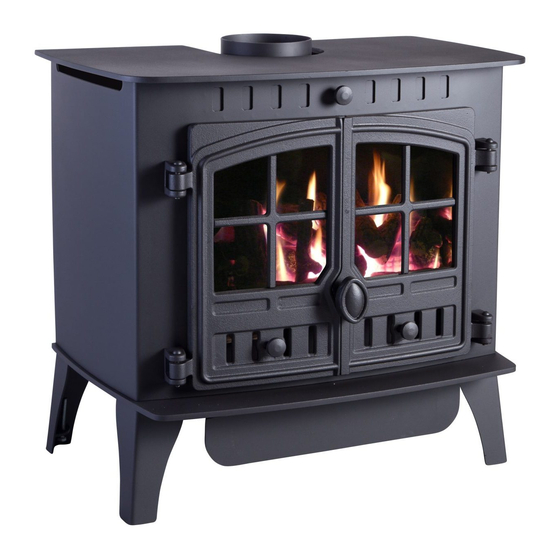
Gas stove
Show thumbs
Also See for HERALD 6:
- Installation and operating instructions manual (17 pages) ,
- Installation and operating instructions manual (15 pages) ,
- Installation, operating and maintenance manual (40 pages)
Table of Contents
Quick Links
HERALD 6
GAS STOVE
Installation and Servicing
Instructions
Please leave this instruction booklet with the user after the installation is
complete. Leave the system ready for operation and instruct the user in the
correct use of the appliance and operation of its controls.
Please refer to the appliance data plate for the specific model type.
Table of Contents

Related Manuals for Hunter Stoves HERALD 6


Summary of Contents for Hunter Stoves HERALD 6
- Page 1 HERALD 6 GAS STOVE Installation and Servicing Instructions Please leave this instruction booklet with the user after the installation is complete. Leave the system ready for operation and instruct the user in the correct use of the appliance and operation of its controls.
-
Page 2: Table Of Contents
Contents TECHNICAL DATA ......... 3 ....................3 TOVE IMENSIONS INSTALLING THE APPLIANCE ....4 ..................4 INSTALLATION NOTES ....................5 RRANGEMENT (GB O ) ..............5 DDITIONAL ENTING ...................6 EMOVING THE TOVE Removing the Cast Iron Doors ................6 Removing the Stove Body ..................6 ..................7 UPPLY ONNECTIONS ..................7... -
Page 3: Technical Data
TECHNICAL DATA NATURAL GAS Nominal Gas Pressure 20mBar 37mBar Supply Gas Type/Category G20/I G31/I Jet Type/Size 82/380 92/190 Heat Input (Gross) Full 6.5kW 6.4 kW 4.2kW 3.7 kW Gas Flow Rate (m Full 0.62 m 0.236 m Class Efficiency Class Countries of Destination GB &... -
Page 4: Installing The Appliance
INSTALLING THE APPLIANCE Pre-installation notes 1. Check the stove data plate to establish the gas type required. The data plate can be found on a chain at the top left rear corner of the stove. Before installation check that the local distribution conditions, nature of the gas and pressure, and adjustment of the application are compatible. -
Page 5: Flue Arrangement
The chimney or flue system that is to be fitted to the Herald 6 gas stove must comply with the current rules in force. -
Page 6: Removing The Stove Body
Removing the Stove Body ! To reduce weight it is recommended that the HE BODY OF THE STOVE IS HEAVY cast iron doors be removed before attempting to remove the stove body. Removing the Cast Iron Doors Open the right-hand door. While holding the door with one hand, gently push up the two hinge pins (Top and bottom) with the other hand. -
Page 7: Gas Supply Connections
Gas Supply Connections The appliance is supplied with a 8mm Bundy pipe and a 8mm compression elbow to allow easy connection to the mains gas supply. This supply gas pipe should incorporate a gas service isolation tap that is situated within 1 metre of the application. Diagram 6 shows the 8mm Bundy pipe being fitted to the gas inlet on the valve. -
Page 8: Installation Of The Fire-Bed Into The Stove
HOT COALS OR LOGS ON OR NEAR COMBUSTIBLE SURFACES. NO RESPONSIBILITY FOR ANY INJURY HOWEVER CAUSED WHILST HANDLING HOT COALS, LOGS OR CERAMICS CAN BE ACCEPTED BY HUNTER STOVES LTD. FIRE-BED ARRANGEMENT This appliance can be fitted with either ‘coal effect’ or ‘log effect’ ceramics. -
Page 9: Section A - Fitting The Coal Effect Ceramic Matrices
Section A - Fitting the Coal Effect Ceramic Matrices : The fire-bed is constructed of 3 ceramic matrices, 4 small coals, 10 ATURAL medium coals and 4 large ‘diamond shaped’ coals. LPG: The fire-bed is constructed of 3 ceramic matrices, 10 small coals, 4 medium coals and 4 large ‘diamond shaped’... -
Page 10: Fitting The Loose Ceramic Coals
Fitting the Loose Ceramic Coals 4. The first row of coals consists of 4 small coals and 4 large coals. The first row of coals are placed so that they sit on top of the front and middle ceramic matrices. Starting with a large ‘diamond shaped’... -
Page 11: Section B - Fitting The Log Effect Ceramic Matrices
The fire-bed should now be completed. The stove should be lit and the flame picture checked with the glass panel fixed securely in place. Any adjustments to the flame picture can then be made as required. The stove can now be re-assembled as shown in ‘Re-assembling the Stove’ – Page 14 Section B - Fitting the Log Effect Ceramic Matrices The fire-bed is constructed of 3 ceramic matrices and 6 loose logs. -
Page 12: Fitting The Loose Ceramic Logs
Fitting the Loose Ceramic Logs D. Starting with the Y-shaped log, place at the angle shown in diagram B11. The bottom of the log should sit in the cut-out on the front ceramic matrix, with the flat underside of it resting on the flat area on the middle matrix. - Page 13 G. The fourth log is the shorter of the two straight logs. The log should rest on the middle ceramic on the flat section to the right of the large log. The top of the log should rest in the groove on the rear ceramic, as shown in diagram B14.
-
Page 14: Fitting The Canopy - (Optional )
– (O ITTING THE ANOPY PTIONAL There are two types of canopy available for your Hunter Herald 6 gas stove. The options available are: • Low Canopy • High Canopy Both canopies fit in exactly the same way. Once the stove body has been secured, the canopy... -
Page 15: Spillage Monitoring System
The system MUST NOT be adjusted or changed by the installer. Replacement systems must be obtained from Hunter Stoves; no other pilot assembly must be substituted in its place. OPERATING THE APPLIANCE... -
Page 16: Attaching The Remote Control Receiver Box
Knob B Turn the main burner control knob (Knob ‘B’ – diagram 19) fully anti-clockwise until the end stop is reached. Diagram 19 Motor Fit the motor as shown in diagram 20, making sure that the motor sits on the locating pin. Replace the valve cover and tighten the Philips headed screw. -
Page 17: Servicing Instructions
It must be understood that any recommendations made here are in addition to the standard servicing procedures used by the servicing engineer. 1. A CORGI registered fitter using only original Hunter Stoves parts should carry out servicing. 2. Remove the stove body and glass as described on Page 6 (Removing the Stove Body). -
Page 18: Spares List
SPARES LIST PART DESCRIPTION PART NUMBER Bundy Tube – Main Burner HG06/032 Bundy Tube – Pilot HG06/033 Bundy Tube -- Inlet HG06/034 LPG Burner Injector HG06083 Nat. Gas Burner Injector HG01BU024 Flue Collar HG06/038 Flue Blanking Plate HG06/037 Flue Gasket HG01CE001 Glass Panel HG06/036...