Table of Contents
Y9120H Sundial RF ² Pack 1
INSTALLATION INSTRUCTIONS
Application
This pack provides a wireless control solution for adding a wireless room
thermostat to new and existing heating systems.
Pack contents & Product Descriptions
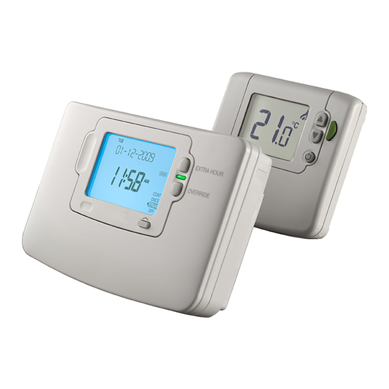
1 x ST9120C1003
Wireless enabled 7 day timer with 1 output control
relay for switching boilers, pumps or zone valves
in heating systems. It requires permanent mains
230Vac power.
1 x DTS92E1020
Wireless digital room thermostat with energy
saving ECO function. It operates on 2xAA alkaline
batteries, giving a battery life of at least 2 years
under typical operating conditions.
1 x table stand for DT92E (optional)
Other Honeywell products may be required for a complete installation.
See Schematic System Layout (below) or refer to www.honeywelluk.com
for full details.
Schematic System Layout
C
old
F
eed
B
oiler
Honeywell
2-way wireless
Sundial RF ² is a registered trademark of Honeywell Inc.
communication
System Operation
DT92E and ST9120C both use 2-way communication on an 868MHz
radio frequency (RF) band to control the heating and stored hot water
system.
ST9120C operates as the control hub of the system, and DT92E is free to
be positioned anywhere in the living space.
This functionality is ideal for upgrading existing systems without a room
thermostat to ensure compliance with Building Regulations. It is also
ideal for new or refurbished systems, where running mains cable from the
timer to the thermostat and back to the boiler is difficult or impractical.
st9120C
r
adiator
1
dt92e
(
)
s
Table of Contents

Related Manuals for Honeywell Y9120H Sundial RF² Pack 1


Summary of Contents for Honeywell Y9120H Sundial RF² Pack 1
-
Page 1: Installation Instructions
1 x ST9120C1003 Wireless enabled 7 day timer with 1 output control 2-way wireless Sundial RF ² is a registered trademark of Honeywell Inc. communication relay for switching boilers, pumps or zone valves in heating systems. It requires permanent mains 230Vac power. -
Page 2: Table Of Contents
The RF link between the Room Thermostat (DT92E) and the Timer Section Page (ST9120C) in Honeywell system packs is pre-configured at the factory 1 INSTALLING THE ST9120C TIMER ......3 and therefore both units should be installed at the same site. -
Page 3: Installing The St9120C Timer
Tighten the two securing screws using a screwdriver. Switch on the power – the unit will now be operating according to the built-in programme. Note: the ST9120C is supplied with a factory set clock for faster installation. Refer to Y9120H User Guide for programming details. -
Page 4: St9120C Internal Wiring
1.5 ST9120C Internal Wiring Notes DT92E is completely wireless and so is not shown connected on these wiring diagrams. The ST9120C is a Class II (double insulated) device. A parking Clock terminal is provided for earth wiring continuity, if required. ST9120C is suitable for contact-closure potential free or mains N L 1 2 3 4 230V~... -
Page 5: Replacement Wiring
If using ST9120C to replace other Honeywell Timers, the equivalent wiring terminations are shown in the tables below. ST6100, ST9100 * ST9120C * Note: If replacing ST6100S or ST9100S, please refer to Honeywell for wiring details as the wiring for the Service Timeout feature may have to change, depending on the application. ST7000B... -
Page 6: Installing The Dt92E Room Thermostat
2.3 to conduct the Signal Strength Test. 2.3 Signal Strength Test Honeywell 2-way RF communications allows signal strength testing to ensure DT92E can be positioned in the best possible location. To enter Signal Strength Test:... -
Page 7: Mounting Dt92E
2.4 Mounting DT92E DT92E can be mounted (a) directly on a wall, or (b) on the optional table stand provided. Wall mounting is recommended as it ensures a position of high signal strength can be maintained. For wall mounting, install the mounting plate first, then follow If the optional table stand is to be used, first assemble the two steps 1, 2 and 3 to hinge the front piece on, as shown in the pieces together as shown. -
Page 8: System Configuration: St9120C
SYSTEM CONFIGURATION: ST9120C 3.1 ST9120C Installer Modes ST9120C has 3 Installer Modes that enable the product to be customized for the application and for the needs of the User. Each adjustable feature is called a Parameter, and is represented by a number or letter ID and a value. The Modes are:- •... -
Page 9: Installer Setup
3.3 Installer Setup The wireless system can be set up to operate in a variety of different ways to suit the application, or the user lifestyle or preferences. This setup is done via the ST9120C Installer Setup. The features that can be adjusted are called Installer Parameters, and are listed in the table below, along with a description of the options that are possible. -
Page 10: Installer Setup Flowchart
3.4 Installer Setup Flowchart LoT™ Display Parameter Parameter Number Value 3.5 Set Service Set Service parameters are listed in the table below, along with a description of the options that are possible. ‘SET SERVICE’ Parameter LoT™ Display Default Range of Description [LoT™... - Page 11 3.5 Set Service (cont.) To Enter Set Service Mode: Enter Installer Modes (as described on Page 8) and navigate to SET SERVICE mode. In response to the query ‘SET SERVICE OK ?’ press the button to enter SET SERVICE. The message ‘ENTER PIN’ will now be displayed, along with the 4-digit entry code format 0---.
-
Page 12: Change Pin
3.6 Change PIN If you intend to change the PIN code, please ensure you take a note of the new code that you are setting. The process for changing the current PIN code is as follows: Enter Installer Modes (as described on Page 8) and navigate to CHANGE PIN mode. In response to the query ‘CHANGE PIN OK ?’ press the button to enter CHANGE PIN mode. -
Page 13: System Configuration: Dt92E
SYSTEM CONFIGURATION: DT92E 4.1 DT92E Installer Mode Like ST9120C, DT92E also has an Installer Mode to enable it to be Parameter Value customized for the application. Each adjustable feature is called a Parameter, and is represented by a letter ID and a value on the display, as shown. -
Page 14: Binding / Re-Binding Procedure
BINDING / RE-BINDING PROCEDURE 5.1 Binding 2-way RF devices that communicate with each other achieve this through having each others unique addresses written in their memories. This allows each device to know which other device to communicate with. The process of writing these addresses is know as Binding. All devices in the pack are pre-bound at the factory. -
Page 15: How To Bind Dt92E To St9120C
5.4 How to Bind DT92E to ST9120C Hold DT92E (or its front section, minus mounting plate) approximately 1 metre from ST9120C. Put DT92E into binding mode and reset (clear) any existing binding information as shown. - Press and hold the button for 2 seconds - Hold the buttons for 3 seconds until display shows ‘Inst’... -
Page 16: Commissioning The System
Honeywell for guidance. Honeywell cannot be held responsible for misapplication of the product(s) described within this document. Manufactured for and on behalf of the Environmental and Combustion Controls Division of Honeywell Technologies Sàrl, ACS-ECC EMEA, Z.A. La Pièce 16, 1180 Rolle, Switzerland, by its Authorised Representative Honeywell Inc.