Table of Contents

Related Manuals for Toshiba MCY-MAP0604HT8


Summary of Contents for Toshiba MCY-MAP0604HT8
-
Page 1: Installation Manual
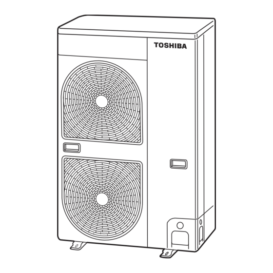
AIR CONDITIONER (MULTI TYPE) Installation Manual Outdoor Unit For commercial use Para uso comercial Model name: Para utilização comercialMCY-MAP0604HT8 MCY-MAP0804HT8 MCY-MAP0604HT7 MCY-MAP0804HT7 English Installation Manual Español Manual de instalación Português Manual de instalação... -
Page 2: Table Of Contents
/ or vibration may result. • If using separately sold products, make sure to use Toshiba specified products only. Using unspecified products may cause fire, electric shock, water leak or other failure. - Page 3 Installation Manual Installation Manual Outdoor Unit Outdoor Unit Refrigerant piping Relocation • Install the refrigerant pipe securely during the installation work before operating the air conditioner. If the compressor is • Only a qualified installer(*1) or qualified service person(*1) is allowed to relocate the air conditioner. It is dangerous for the operated with the valve open and without refrigerant pipe, the compressor sucks air and the refrigeration cycles is over air conditioner to be relocated by an unqualified individual since a fire, electric shocks, injury, water leakage, noise and / or pressurized, which may cause a injury.
-
Page 4: Accessory Parts
Installation Manual Installation Manual Outdoor Unit Outdoor Unit – 3 – Accessory parts Installation of new refrigerant air conditioner Part name Q’ty Shape Usage This air conditioner adopts the new HFC refrigerant (R410A) which does not deplete the ozone layer. Owner’s Manual Hand this directly to the customer. -
Page 5: Installation Conditions
Installation Manual Installation Manual Outdoor Unit Outdoor Unit Installation conditions Installation location WARNING Before installation Install the outdoor unit properly in a location that is durable enough to support the weight of the outdoor unit. Be sure to prepare to the following items before installation. Insufficient durability may cause the outdoor unit to fall, which may result in injury. - Page 6 Installation Manual Installation Manual Outdoor Unit Outdoor Unit – 5 – Necessary space for installation CAUTION (Unit: mm) 1. Install the outdoor unit in a location where the discharge air is not blocked. 2. When an outdoor unit is installed in a location that is always exposed to strong winds like a coast or on the high Obstacle at rear side stories of a building, secure normal fan operation by using a duct or wind shield.
-
Page 7: Installation Of Outdoor Unit
Installation Manual Installation Manual Outdoor Unit Outdoor Unit Installation of outdoor unit Obstacles in both front and rear of unit Open above and to the right and left of the unit. • Before installation, check the strength and horizontalness of the base so that abnormal sounds do not emanate. The height of an obstacle in both the front and rear of the unit, should be lower than the height of the outdoor unit. -
Page 8: Refrigerant Piping
Installation Manual Installation Manual Outdoor Unit Outdoor Unit – 7 – Refrigerant piping • When water is to be drained through the drain hose, attach the following drain nipple and waterproof rubber cap, and use the drain hose (Inner diam: 16 mm) sold on the market. Also seal the knockout hole and screws securely with silicone material, etc., to prevent water from leaking. -
Page 9: Refrigerant Piping Connection
Installation Manual Installation Manual Outdoor Unit Outdoor Unit Optional installation parts (locally procured) Connecting the pipe at the gas side (MCY-MAP0804HT8 / HT7 only) Parts name Q’ty Refrigerant piping REQUIREMENT Liquid side: Ø9.5 mm One each • Connecting the main pipe (Ø19.1) directly to the gas valve (Ø19.1) may lower the performance. Gas side: Ø19.1 mm and Ø22.2 mm •... - Page 10 Installation Manual Installation Manual Outdoor Unit Outdoor Unit – 9 – Tightening of connecting part Coupling size of brazed pipe Connected section 1. Align the centers of the connecting pipes and fully tighten the flare nut with your fingers. Then fix the nut with a wrench as shown in the figure and tighten it with a torque wrench.
- Page 11 Installation Manual Installation Manual Outdoor Unit Outdoor Unit Selection of pipe materials and size Selection of refrigerant piping ◆ Selection of pipe material Material: Phosphorus deoxidation seam-less pipe Outdoor unit ◆ Capacity code of indoor and outdoor units •...
- Page 12 Installation Manual Installation Manual Outdoor Unit Outdoor Unit – 11 – Selection of refrigerant piping for quiet place (with PMV Kit) Piping parts Name Selection of pipe size Selection of branching section (Y-shaped branching joint) Y-shaped Model name Branching section branching joint Y-shape branching joint RBM-BY55E...
- Page 13 Installation Manual Installation Manual Outdoor Unit Outdoor Unit ◆ Allowable length / height difference of refrigerant piping Piping parts Name Selection of pipe size Selection of branching section (Y-shaped branching joint) Y-shaped Model name Branching section branching joint Outdoor unit Y-shape branching joint RBM-BY55E Selection of branching section (Branching header)
- Page 14 Installation Manual Installation Manual Outdoor Unit Outdoor Unit – 13 – ◆ Allowable length / height difference of refrigerant piping for quiet places NOTE (with PMV Kit) Do not connect two or more indoor units to one PMV Kit. Arrange one indoor unit and one PMV Kit set to 1 by 1. NO GOOD Outdoor unit PMV Kit...
- Page 15 Installation Manual Installation Manual Outdoor Unit Outdoor Unit Airtight test REQUIREMENT When pressure decrease is detected in steps 1-3, check the leakage at the connecting points. Before starting an airtight test, further tighten the spindle valves on the gas side and liquid side. Check the leakage using a foaming agent or other measures and seal the leak with re-brazing, flare retightening or other Pressurize the pipe with nitrogen gas charged from the service port to the design pressure to conduct the airtight methods.
-
Page 16: Air Purge
Installation Manual Installation Manual Outdoor Unit Outdoor Unit – 15 – Air purge Adding refrigerant After finishing vacuuming, exchange the vacuum pump with a refrigerant canister and start additional charging of NOTE refrigerant. For the air purge at installation time (Discharge of air in connecting pipes), use “Vacuum pump method” from viewpoint of the protection of the earths environment. - Page 17 Installation Manual Installation Manual Outdoor Unit Outdoor Unit How to open the valve Example: (0804 type) Open or close the valve. ▼ Liquid side Open the valve with a 4 mm hexagon wrench. ▼ Gas side Valve unit Ø9.5: 10 m Ø9.5: 10 m Ø9.5: 5 m Ø9.5: 3 m...
-
Page 18: Electric Wiring
MOCP: Maximum Overcurrent Protection (Amps) Indoor unit Indoor unit Indoor unit Indoor unit Power Supply MOCP Model Phase and frequency Nominal Voltage MCY-MAP0604HT8 3N~ 50 Hz 380-415 V 16.5 MCY-MAP0804HT8 Remote controller Remote controller MCY-MAP0604HT7 Remote controller 3N~ 60 Hz 380 V 16.5... - Page 19 Installation Manual Installation Manual Outdoor Unit Outdoor Unit ◆ Group control through a remote controller Keep the rule of below tables about size and length of communication wiring. Group control of multiple indoor units (8 units) through a single remote controller Central controller S-MMS...
- Page 20 Installation Manual Installation Manual Outdoor Unit Outdoor Unit – 19 – 2. Use round-type crimping terminals for power connection. Also, apply insulating sleeves to the crimping parts. Use a driver of appropriate size to fix the terminal screws. Communication terminal block Power supply terminal block Earth screw...
-
Page 21: Address Setting
Installation Manual Installation Manual Outdoor Unit Outdoor Unit Address setting ◆ Communication wire connection Get the communication wire through the cutout on the side of the electrical control box and connect it to the On this unit, it is required to set the addresses of the indoor units before starting air conditioning. communication wire terminals, then fix it with the communication cable clamp. - Page 22 Installation Manual Installation Manual Outdoor Unit Outdoor Unit – 21 – Auto 1 Auto 2 Auto 3 The 7-segment display indicates Interface P.C. board on the outdoor unit After the indication, U. 1. - - - (U. 1. flash) starts flashing on the display.
- Page 23 Installation Manual Installation Manual Outdoor Unit Outdoor Unit Be sure to disconnect the relay connectors between the [U1,U2] and [U3,U4] terminals on all the Connect the relay connectors between the [U1, U2] and [U3, U4] terminals of the outdoor unit of outdoor units that will be connected to the central control.
- Page 24 Installation Manual Installation Manual Outdoor Unit Outdoor Unit – 23 – Manual address setting with the remote controller Switch setting (setting example when controlling 2 or more refrigerant lines centrally) Outdoor units (setting manually) Procedure when setting indoor units’ addresses first under the condition that indoor wiring has been completed and *The items in bold font must be set manually.
-
Page 25
Installation Manual Installation Manual Outdoor Unit Outdoor Unit Confirming the indoor unit addresses and the position of an
indoor unit using the remote controller Push the TEMP. buttons repeatedly to set the CODE No. to Push the TIME buttons repeatedly to set a system address. - Page 26 Installation Manual Installation Manual Outdoor Unit Outdoor Unit – 25 – ◆ To select another system address (Execute it while the units are stopped.) The indoor unit numbers in a group are indicated one after another. The fan and louvers of the indicated units are activated.
- Page 27 Installation Manual Installation Manual Outdoor Unit Outdoor Unit ▼ To change all the indoor unit addresses using an arbitrary wired remote controller. Push the TIME buttons repeatedly to change the value of the indoor unit address in SET (The method is available when the addresses have already been set automatically.) DATA.
-
Page 28: Test Run
Installation Manual Installation Manual Outdoor Unit Outdoor Unit – 27 – Test run Turn on the indoor and outdoor units of the refrigerant line for which you want to initialize the addresses. About one minute after turning on the power, confirm that the 7-segment display on the outdoor unit indicates “U.1. - Page 29 Installation Manual Installation Manual Outdoor Unit Outdoor Unit ◆ When executing a test run using the interface P.C. board on the outdoor Push and hold the TEST button for more than 4 seconds. TEST appears on the LCD display and the unit enters the test mode.
- Page 30 Installation Manual Installation Manual Outdoor Unit Outdoor Unit – 29 – ▼ Finishing operation ▼ Stop operation Set the rotary switches on the interface P.C. board of the outdoor unit back: SW01 to [1], SW02 to Set the rotary switches on the interface P.C. board of the outdoor unit back: [1] and SW03 to [1].
-
Page 31: Troubleshooting
Installation Manual Installation Manual Outdoor Unit Outdoor Unit Troubleshooting Check code Indication on 7-segment display on the outdoor unit Check code name In addition to the CODE No. on the remote controller of an indoor unit, you can diagnose failure type of an outdoor Auxiliary code unit by checking the 7-segment display on the interface P.C. - Page 32 WARNINGS ON REFRIGERANT LEAKAGE Check of Concentration Limit Important The room in which the air conditioner is to be installed NOTE 2 : requires a design that in the event of refrigerant gas The standards for minimum room volume are as leaking out, its concentration will not exceed a set limit.