Table of Contents
Quick Links
See also:
Operating Manual
Table of Contents

Related Manuals for Sony HDLA1500


Summary of Contents for Sony HDLA1500
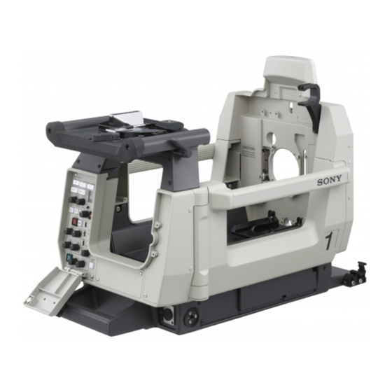
- Page 1 LARGE LENS ADAPTOR HDLA1500 HDLA1505 LARGE VIEWFINDER ADAPTOR HDLA1507 OPERATION MANUAL [English] 1st Edition (Revised 1)
- Page 2 (commercial et industrie légère), E3 (urbain extérieur) et E4 (environnement EMC contrôlé, ex. studio de télévision). Fachpersonal. Le fabricant de ce produit est Sony Corporation, 1-7-1 Konan, Minato-ku, Tokyo, Japon. For the customers in the U.S.A. Le représentant autorisé pour EMC et la sécurité des produits...
- Page 3 E1 (Wohnbereich), E2 (kommerzieller und in beschränktem Maße industrieller Bereich), E3 (Stadtbereichim Freien) und E4 (kontrollierter EMV-Bereich, z.B. Fernsehstudio). Der Hersteller dieses Produkts ist Sony Corporation, 1-7-1 Konan, Minato-ku, Tokyo, Japan. Der autorisierte Repräsentant für EMV und Produktsicherheit ist Sony Deutschland GmbH, Hedelfinger Strasse 61, 70327 Stuttgart, Deutschland.
-
Page 4: Table Of Contents
Preparations with the Adaptor ........... 14 Mounting the Camera in the Adaptor ........15 Attaching a Large Viewfinder (HDLA1500/1507) ....18 Attaching a Large Studio Lens (HDLA1500/1505) ....20 Mounting on the Tripod.............21 Connecting the Camera Cables ..........21 Attaching the Number Plates............. 21 Attaching the Supplied Plate ............. -
Page 5: Foreword
The HDLA1500/1505 Large Lens Adaptor, in models combination with a viewfinder among various types, This manual describes three models of the HDLA1500 allows the camera to be fitted with a large lens of high series: the HDLA1500 and HDLA1505 Large Lens magnification, yielding high-speed controlability for Adaptors, and the HDLA1507 Large Viewfinder Adaptor. -
Page 6: System Configuration
The special mechanism that Peripherals and related devices for the HDLA1500 series requires no adjustment is employed also for connection of are shown in the figures. - Page 7 HDLA1505 HDLA1507 HDVF-C550W/C730W/EL75 Viewfinder HD Color Camera + Lens Camera Control Unit HD Color Camera CAC-6 Return Video Selector Camera Control Unit Camera hangers Intercom (supplied with Headset HDLA1505) CAC-6 Return Video HDVF-700A Selector HDVF-EL70 Viewfinder Intercom Headset Zoom Lens (for studio use) HDLA1507 HDLA1505...
-
Page 8: Precautions
Precautions Do not subject to severe shocks Damage to the case or internal components may result. Operation and storage environment Store in a level place with air conditioning. Avoid use or storage in the following places: • Extremely hot or cold places •... -
Page 9: Locations And Functions Of Parts
Locations and Functions of Parts Side Panel HDLA1500 b Camera handle catch Viewfinder table (page 18) a Tally lamp Viewfinder table lock lever (opposite side) Viewfinder table release knob Lens mount (front) (page 20) Rear panel lock release lever c Holder for camera... - Page 10 HDLA1507 Viewfinder table (page 18) Viewfinder table lock lever (opposite side) Viewfinder table release knob Rear panel lock release lever c Holder for camera number plate e DC OUT connector f Accessory bracket d Cable clamp g DC OUT connector a Tally lamp [1500][1505] f Accessory bracket The lamp lights when a red tally signal is supplied to the...
-
Page 11: Rear Panel
Rear Panel HDLA1500 HDLA1507 Control panel Control panel (page 12) (page 12) POWER POWER RET 1 RET 2 RET 1 RET 2 2 3 4 2 3 4 2 3 4 2 3 4 VF DTL VF DTL CURSOR CURSOR... -
Page 12: Control Panel
Control Panel a POWER indicator POWER b Video signal select buttons m Back tally lamp RET 1 RET 2 c RET 1 button and selector knob 2 3 4 2 3 4 n RET 2 button and selector knob o VF DTL switch VF DTL p CALL button CURSOR... - Page 13 n RET 2 button and selector knob Note You may select from among the four return signals (1 to 4) When one of the CURSOR buttons is lit, the H-POSI, V- from the CCU using the selector knob. POSI, WIDTH, and HEIGHT buttons do not function. By pressing the button, you can view the return video signal selected by the selector knob, on the viewfinder e CURSOR STORE button...
-
Page 14: Installation
ON ( ): The screen size marker (white lines) will be Preparations with the Camera displayed. (HDLA1500/1505) OFF: The screen size marker will not be displayed. Attach the camera hangers supplied with the adaptor to the u MARKER switch camera. -
Page 15: Mounting The Camera In The Adaptor
Bottom of the adaptor [1500][1507] Feet Feet Remove the blind bush from the screw hole on the side panel. Cable hanger V-wedge shoe When attaching the V-wedge shoe, taking the total weight Attach the stopper of the adaptor, camera, studio lens and viewfinder, and the using the supplied screw. - Page 16 Viewfinder base Camera lock lever For the HDLA1500, proceed to step 2. For the HDLA1505, proceed to step 3. Pull the viewfinder table lock lever 1 toward the rear panel, then pull the release knob 2 and slide the viewfinder table in the direction of the arrow 3.
- Page 17 This camera release lever on the bottom of the adaptor is used when removing the camera (page 18). Close the rear panel. (The figure shows HDLA1500.) Remove the camera. For the HDLA1500/1505 While holding the camera lock lever on the front panel upward, and pull the camera rearward until it stops then remove it.
-
Page 18: Attaching A Large Viewfinder (Hdla1500/1507)
[1500][1505] (The figure shows HDLA1500.) Camera lock lever (The figure shows HDLA1500.) Caution Check that the rear panel is locked firmly. Attaching a Large Viewfinder (HDLA1500/1507) Attach a large viewfinder to the panning base mounting plate of the adaptor. For the HDLA1507... - Page 19 VF connector of the adaptor. Pull the handle to check that the viewfinder is fixed to Rotate the handle toward the front. the adaptor. In case of the HDLA1500, push the handle into the catch on the adaptor. Installation...
-
Page 20: Attaching A Large Studio Lens (Hdla1500/1505)
If there is a pin at part A on the lens, remove it. Otherwise, the focal length adjustment may not be Release the panning lock lever and turn the viewfinder made. If the pin cannot be removed, consult your Sony 90 degrees clockwise from the operation panel of the representative. -
Page 21: Mounting On The Tripod
Push the rear face of the lens onto the front face of the Note lens adaptor then turn the lens lock holding knob Some tripods cannot be attached unless the feet and cable clockwise. hanger are removed from the adaptor. Remove the feet and Make sure that the lens lock stands back and holds the hanger to use such a tripod (see page 14). -
Page 22: Attaching The Supplied Plate
Attaching the Supplied Plate Note Do not use the supplied plate if the lens and lens mount If the unfinished surface of the front lens mount is exposed profiles mate precisely (no unfinished surfaces exposed). after attaching a lens, use the supplied plate (not available Doing so will create a space between the lens and lens for HDLA1507) to avoid leaving this surface exposed. -
Page 23: Specifications
Camera hangers (2) (HDLA1500/1505) Angle-adjusting plates (2) Cable clamps (2) Number plates for side panel (2 sets) Number plates for up-tally lamp (1 set) (HDLA1500/1505) Stopper (1) (HDLA1500/1507) Fixing screw for stopper (1) (HDLA1500/1507) Plate (1) (HDLA1500/1505) Fixing screws for plate (2) (HDLA1500/1505) - Page 24 Design and specifications are subject to change without notice. Note Always verify that the unit is operating properly before use. SONY WILL NOT BE LIABLE FOR DAMAGES OF ANY KIND INCLUDING, BUT NOT LIMITED TO, COMPENSATION OR REIMBURSEMENT ON ACCOUNT OF THE LOSS OF PRESENT OR...
- Page 25 The material contained in this manual consists of information that is the property of Sony Corporation and is intended solely for use by the purchasers of the equipment described in this manual. Sony Corporation expressly prohibits the duplication of any portion of this manual or the use thereof for any...
- Page 26 Sony Corporation HDLA1500 (JN/CE) Printed in Japan HDLA1505 (JN/CE) 2011.07 08 HDLA1507 (JN/CE) © 2005 4-145-591-02(1)