
Related Manuals for Thermo Scientific Barnstead Nanopure TOC - UV


Summary of Contents for Thermo Scientific Barnstead Nanopure TOC - UV
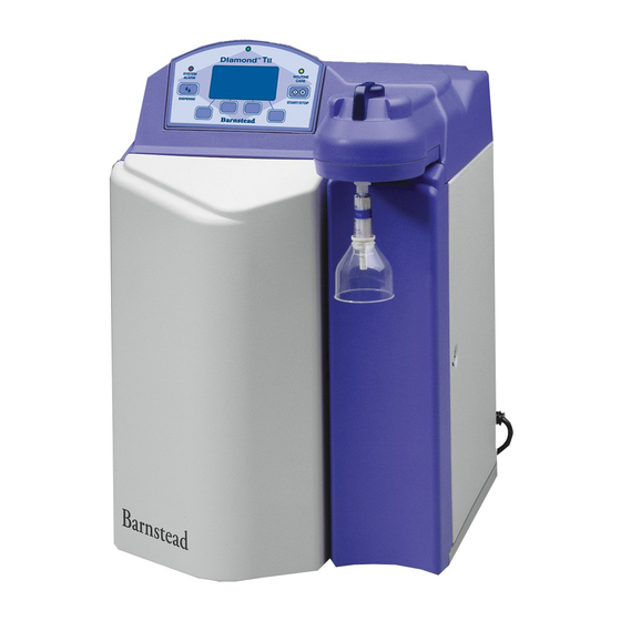
- Page 1 Barnstead Nanopure ™ TOC - UV ultrapure water system Operation Manual Series 2115 and 2117 Model No. Voltage D11951 100V - 240V D12421 100V - 240V LT2115X1 • 11/23/09...
-
Page 2: Table Of Contents
Table of Contents Safety Information ........................................3 Alert Signals ........................................3 Warnings..........................................3 Introduction ............................................5 General Usage ........................................5 General Specifications ........................................6 Environmental Conditions....................................7 Declaration of Conformity ....................................7 Unpacking............................................8 Installation............................................9 Choosing a Site ........................................9 UV Lamp Installation ......................................10 Other Accessories ......................................10 Bench Mounting ........................................11 Wall Mounting ........................................11 Installing the Control Panel in a Remote Location ............................12 Water Connections ......................................13... -
Page 3: Safety Information
Safety Information Your Thermo Scientific Barnstead Nanopure TOC - UV Alert Signals ultrapure water system has been designed with function, reliability, and safety in mind. It is your responsibility to install it in conformance with local electrical codes. This manual contains important safety information. You must... - Page 4 AFETY NFORMATION Avoid splashing cleaning solutions on clothing or skin. Ensure all piping connections are tight to avoid chemical leakage. Ensure adequate ventilation. Carefully follow manufacturer’s safety instruc- tions on labels of chemical containers and mate- rial safety data sheets. Depressurize system prior to removing the cartridge pack.
-
Page 5: Introduction
Introduction Congratulations on your purchase of a Barnstead Nanopure TOC - UV ultrapure water system. This water purification system is designed to provide low TOC, high resistivity, reagent grade water that exceeds ASTM Type I, ISO 3696 and CLSI-CLRW Type I standards. It uses a four-stage deionization process combined with a UV lamp and a 0.2 micron filter to polish suitable feed water (dis- tilled, deionized, or reverse osmosis) to produce low TOC... -
Page 6: General Specifications
General Specifications Dimensions and Clearance Requirements Dimensions 13.5” W x 19.5” H x 17.0” D (34.3 x 49.5 x 43.2 cm) Clearances Sides - 9” (22.9 cm) minimum for servicing. Above - 3” (7.6 cm) minimum for removal of the top cover. Front - 4.75”... -
Page 7: Environmental Conditions
ENERAL PECIFICATIONS Electrical Requirements The Nanopure TOC - UV is equipped with 2 power cords to be plugged into an electrical outlet of the appro- priate voltage. U.K. customers use cord, CRX100 and fuses for 240V installation. Model D11951, D12421 100-240 VAC, 100 watts, 47-63 Hz, 1 phase Environmental Conditions Operating: 4°C - 40°C;... -
Page 8: Unpacking
Unpacking Remove the unit from its shipping container. Remove all contents carefully. Ensure that the UV lamp, feed and drain tubing, cleaning car- tridge, wall bracket, accessory parts bag and power cords (see list below) are removed from the packaging materials before discard- ing. -
Page 9: Installation
Installation Choosing a Site Caution The Nanopure TOC - UV features a removable control Wall composition, condition and panel display which allows the system to be mounted construction as well as fastener type almost anywhere within the laboratory. Use the wall must be considered when mounting bracket for wall mounted systems as a template to drill this unit. -
Page 10: Uv Lamp Installation
NSTALLATION UV Lamp Installation Note Locate the UV chamber inside the left door of the The UV lamp contains mercury. If Nanopure TOC - UV. Install the UV Lamp as follows: broken or no longer needed, do not Disconnect the power cord from the unit. dispose of the UV lamp in the trash. -
Page 11: Bench Mounting
NSTALLATION Bench Mounting Caution Place the Nanopure TOC - UV on a bench top Wall composition, condition and con- that is accessible to pretreated water, electricity struction, as well as fastener type, and an atmospherically vented drain. must be considered when mounting this unit. -
Page 12: Installing The Control Panel In A Remote Location
NSTALLATION Note The removable control panel was not designed to be repeatedly removed Installing the Control Panel in a from the unit, therefore, you may experience difficulty when attempting Remote Location to remove it. It is therefore For your convenience, the control panel can be removed recommended that the control panel from the unit and mounted at a convenient location within be permanently mounted in a remote... -
Page 13: Water Connections
NSTALLATION Caution Do not connect feed water until direct- ed to do so during “Initial Cleaning.” Water Connections Feed Water Connection Locate the length of 3/8” O.D. tubing provided with the unit with a quick disconnect insert on Accudispense one end and a 3/8” (.95 cm) O.D. X 1/4” (.64 control cable cm) NPT tubing adapter on the other. -
Page 14: Tubing Installation
NSTALLATION Tubing Installation To make tubing connections: Make sure the tubing is cut off reasonably COLLET square and that no plastic burrs or ridges are present. TYPICAL TUBING FITTING *Mark from end of tube the length of insertion. Tube size Insertion length 1/4 O.D. -
Page 15: Controls
Controls Main Power Switch The main power switch on the Nanopure TOC - UV is located on the lower back right side of the unit (as you face the front of the unit), directly above the power cord receptacle. Note Control Panel The removable control panel was not The Nanopure TOC - UV is controlled through a panel... -
Page 16: Switches
ONTROLS Switches When the main power switch (on the lower back right side of the unit as you face the unit) is ON, the switches on the control panel function as follows: START/STOP allows you to alternate the unit between the normal (recirculation) mode;... -
Page 17: Initial Operation
Initial Operation Cartridge packs will come bagged with four manifold connection caps. Part Application DIamond Kit Organic Free R/O & Distilled Feed D50280 Ultra-Low Organics, Type 1 Water, Reverse Osmosis or Distilled Water Feed DIamond Kit Organic Free Deionized Feed Warning D50281 Ultra-Low Organics, Type 1 Water, Depressurize system prior to removing... -
Page 18: Initial Rinse
NITIAL PERATION Initial Rinse Attach the feed water line to the unit by snap- ping the quick disconnect coupling into the quick disconnect body in the lower left back of the unit. Attach an atmospheric drain line [1/4” (.64 cm) ] tubing by pushing into the quick connect fitting on the lower left back of unit. -
Page 19: System Cleaning Procedure
NITIAL PERATION 11. Upon completion of the air purge, press the UP or DOWN arrow until “TOC Short Flush?” dis- Warning plays. Press ENTER. (This flush will last approx- Avoid splashing cleaning solution on imately 20 seconds.) clothing or skin. 12. - Page 20 NITIAL PERATION Remove syringe luer cap and attach syringe to the system luer fitting. Slowly inject solution into system and remove syringe. Avoid injecting air into the system. 10. Replace luer cap on injection port and close door. 11. Press the UP or DOWN arrow to select (YES) and then press ENTER.
-
Page 21: Normal Operation
Normal Operation Note On initial start-up, the purity meter Turn the system power ON by depressing the main may display “...M -cm or uS/cm.” This power switch to the “I” position. is caused by air in the cell and should be replaced by a resistivity reading The system greeting display indicates the type of almost immediately. -
Page 22: Dispensing Water
ORMAL PERATION Dispensing Water Note Use the dispense knob for manual dispensing or, use the Press any switch except ENTER to “Dispense” switch for volumetric or timed dispensing. See stop dispensing. Display will read, “User Settings.” “Auto Dispense Interrupted by User.” Automatic Dispensing Note (Factory set to “OFF.”) This feature is accessible only... -
Page 23: User Settings
User Settings Adjusting Display Brightness From the (Idle) mode, when the display reads, “Nanopure (Idle) xx:xx:xx xx/xx/xx,” press the UP or DOWN arrow until display reads, “Advanced Menu?” Press ENTER. Press ENTER to proceed through the options until “Set Display Brightness” is displayed. Press the UP or DOWN arrow to choose “Yes.”... -
Page 24: Setting The Date And Time
ETTINGS Setting the Date and Time Note From the (Idle) mode, when the display reads, Time values are displayed in 24 hr. “Nanopure (Idle) xx:xx:xx xx/xx/xx,” press the military time. For example; 6:00p.m. = UP or DOWN arrow until display reads, 18:00:00 = hr./min./sec.) “Advanced Menu?”... -
Page 25: Setting The Cell Constant
ETTINGS Setting the Cell Constant The actual temperature and cell constants are attached to the cell cable internal to the Nanopure unit. This data helps ensure that the purity displayed is as accurate as possible. The only time the user would need to enter this data is if the cell or main board is being replaced and/or updated. -
Page 26: Use Of Standby Mode
ETTINGS 15. Press ENTER. 16. Press BACK twice to return to the (Idle) mode. Use of Standby Mode At the end of the work day, place the Nanopure TOC - UV in Standby mode for the night. To place the unit in Standby mode: From the (Idle) mode, when display reads, “Nanopure (Idle) xx:xx:xx xx/xx/xx,”... -
Page 27: Resetting The Cleaning Timer
ETTINGS Press the UP or DOWN arrow to choose “Yes.” Press ENTER. Press the UP or DOWN arrow until the desired value is displayed. Press ENTER. Press BACK to return to the (Idle) mode. The second line of the display will show a “Below Set point”... -
Page 28: Resetting The Uv Timer
ETTINGS Resetting the UV Timer When the Nanopure TOC - UV is in an (Idle) position: Note From the (Idle) mode, when display reads, When the user begins receiving “Nanopure (Idle) xx:xx:xx xx/xx/xx,” press the “Change UV Lamp” reminders, it will UP or DOWN arrow until the display reads, be time to change UV lamp and “Reset Timers?”... -
Page 29: Using The Toc Analyzer
ETTINGS Using the TOC Analyzer (Factory set to “No.”) This feature is accessible from the (Idle) mode. Use the analyzer when TOC values and resistivity/con- ductivity readings are to be displayed. DO NOT use the analyzer when only resistivity/conductivity readings are to be displayed. -
Page 30: Setting Volumetric Dispensing
ETTINGS Setting Volumetric Dispensing Note From the normal recirculating mode, when the dis- Volumetric dispensing is based upon play is showing purity, press the UP or DOWN arrow total fluid volume entering the until the display reads, “Auto Dispense Menu?” Nanopure TOC - UV. -
Page 31: Performing A System Flush
ETTINGS Performing a System Flush Note From the normal recirculating mode, when the An automatic 1-minute flush will occur display is showing purity, press the UP or once every 12 hours. If a unit is (Idle) DOWN arrow until the display reads, “System or in STANDBY for over 12 hours, an Flush?”... -
Page 32: Auto Standby
ETTINGS Auto Standby (Factory set to “NO”) Note This option allows for a convenient method for the user to If set to “YES”, unit will automatically ensure that the Nanopure TOC - UV unit will be placed in enter Standby Mode only once per Standby at a predetermined time each day. - Page 33 ETTINGS until “UNIT UNDER COUNTER” is displayed. Press the UP or DOWN arrow to choose “YES.” Press ENTER. Press BACK until you return to the (Idle) dis- play.
-
Page 34: Accessories
Accessories Feedwater Float or Pressure Switch Accessories D8964 (float switch) and D2706 (pressure switch) are designed to protect the Nanopure TOC - UV pump by alerting the system of an inadequate feed water condition so that the pump can be shut down. If an inade- quate feed water condition exists and the pump is shut down due to this condition, the display will read “Check Inlet.”... -
Page 35: Dispense Overflow Cutoff Float
CCESSORIES Dispense Overflow Cutoff Float Caution Accessory AY1367X1 (overflow float with 6 ft [2.83 meter] This accessory is not intended for cable) is designed as a user option to ensure automatic use with small containers as its dispensers (time or volumetric) do not overflow carboy weight could cause small, light- style containers. -
Page 36: Performing An Electronic Calibration Using The Optional N.i.s.t. Calibration Module
CCESSORIES Performing an Electronic Calibration Using the Optional N.I.S.T. Calibration Module If you purchased the optional N.I.S.T. calibration module (Catalog No. E896X5) you can perform a calibration of the Nanopure purity sensing electronics traceable to N.I.S.T. standards. Disconnect power cord from the unit. Unlatch and open the right door. -
Page 37: Manual Remote Dispenser And Accudispense Volumetric Remote Dispenser
CCESSORIES 12. Turn the main power switch to the OFF “O” position. Unplug the unit. 13. Remove the calibration module and reconnect the cell. 14. Reattach the cover plate and close and latch the door. 15. Reconnect the power cord. The calibration procedure is complete. -
Page 38: Computer/Printer Setup
Computer/Printer Setup Connecting Nanopure to Computer and Communicating Through the RS-232 Port Using Hyperterminal or Procomm Hyperterminal RS-232 Capture Instructions Connect the 9 pin serial cable (part no. WHX18) from the Nanopure RS-232 port to COM2: port or (COM1: port) on back of computer. From the (Idle) display, press the UP or DOWN Note arrow until display reads, “Advanced Menu.”... - Page 39 OMPUTER RINTER ETUP called capture.txt and the file will be an ASCII text file. 11. You should see the data on the computer screen. 12. When you are finished storing data from the Nanopure, save your file. You can exit Hyperterminal or set up a new experiment.
-
Page 40: Connecting And Starting The Printer
OMPUTER RINTER ETUP 13. Type in 24, saves settings. 14. Type ESC to exit setup menu. 15. Procomm is now ready to accept input from the Nanopure. 16. To begin downloading a file, Type ALT-F1, and give the file an appropriate name when prompt- The optional printer (part no. -
Page 41: Printer Setup
OMPUTER RINTER ETUP 10. During normal Recirculation mode, a purity and temperature reading will be printed once every 12 minutes. If “Use TOC Analyzer” has been set to “Yes,” the TOC data will also be printed. Printer Setup Power Switch Located on the front of the printer (AY1137X1), this switch turns power to the printer ON and OFF. -
Page 42: Maintenance And Servicing
Maintenance and Servicing General Cleaning Instructions Warning Disconnect electrical service to the unit. Wipe exterior • Avoid splashing mild detergent surfaces with lightly dampened cloth containing mild soap or weak acid on clothing or solution. skin • Ensure all piping connections are tight to avoid chemical Cell Cleaning leakage... -
Page 43: System Cleaning
AINTENANCE AND ERVICING System Cleaning Note It is best to perform cleaning procedures early in the after- The cleaning timer will display after six noon. After cleaning is complete (approximately 3.5 months, reminding you to clean the hours), place the unit into its normal (recirculation) mode unit. -
Page 44: System Depressurization
AINTENANCE AND ERVICING and press ENTER. Display will now read, “Unit Cleaning.” 14. Unit may now be left unattended until the display reads, “Cleaning Complete: Press ENTER.” 15. After cleaning is complete and the user presses “ENTER” the unit will return to the (Idle) mode. 16. -
Page 45: Cartridge Pack Replacement
AINTENANCE AND ERVICING Cartridge Pack Replacement Warning The frequency with which you will need to clean your unit Depressurize system prior to removing and replace your cartridge pack is dependent on your cartridge pack. feed water’s characteristics, your purity requirements and your usage. -
Page 46: 0.2 Micron Filter Replacement
AINTENANCE AND ERVICING 0.2 Micron Filter Replacement Caution Replace the 0.2 micron final filter whenever any of the fol- Do not overtighten the 0.2 micron filter lowing conditions occur: the product water flow rate is or use excessive force in seating it. reduced or bacteria break through. -
Page 47: Uv Lamp Replacement
AINTENANCE AND ERVICING UV Lamp Replacement Warning The ultraviolet lamp requires periodic replacement. Lamp This unit is equipped with an ultraviolet life will vary according to the number of times the lamp. Ultraviolet radiation is harmful to Nanopure TOC - UV is turned on and off (the the eyes and skin. -
Page 48: Toc Lamp Replacement
AINTENANCE AND ERVICING Reconnect the power cord. Turn unit ON. Reset UV Timer according to “Resetting the UV Timer.” Operate normally. Clips TOC Lamp Replacement Place unit in the “Idle” mode. Turn power off. Disconnect the power cord from the power entry module. Open right side door and locate the TOC board at the bottom. -
Page 49: Shutdown
AINTENANCE AND ERVICING Pull out the fuse drawer located in the power entry module. Remove old fuses and replace with fuses of the same type and rating. (See “Replacement Parts.”) Replace fuse drawer. Reattach the power cord. Operate normally. Shutdown If the Nanopure TOC - UV is to be shut down for an extended period of time, the unit should be completely drained and the cartridge pack removed to prevent the... -
Page 50: Troubleshooting
Troubleshooting Problem Possible Causes Solutions Nanopure completely No electrical power to Nanopure. Ensure Nanopure power inactive (pump and display cord is connected to a live power not operating.) source and completely plugged into electrical outlet as well as power entry module on the unit. - Page 51 ROUBLESHOOTING Problem Possible Causes Solutions Poor quality feed water. If a Barnstead ROpure is the feed water source, check that the membrane is functioning properly. If a Barnstead Still is the feed water source, ensure that the distillate temperature to the Nanopure does not exceed 40°C (104°F).
- Page 52 ROUBLESHOOTING Problem Possible Causes Solutions Display reads, “Meter PC board communication error. Turn the Nanopure OFF Board Problem.” (I/O Switch) and restart the unit. System electronics failure. Replace the resistivity meter board mounted on the inside of the right door. Water is leaking between the Wing head screws are not Tighten wing head screws on unit...
- Page 53 ROUBLESHOOTING 005, 007 TOC sensor error. Cycle power, replace TOC Analyzer if it continues. Shorted TOC resistivity sensor. Cycle power and place TOC analyzer in hour long clean mode (under Diagnostics); if still shorted, replace TOC Analyzer. TOC UV lamp error. Verify TOC lamp is connected.
-
Page 54: Replacement Parts
Replacement Parts Recommended Spares Consumables Consumable parts are those required to support the day-to-day operation of this equipment. We established two types of consumables; those items that must periodically be replaced to maintain performance (filters, resin cartridges, etc.) and other items of limited life (indicator lights, fuses, etc.) that you can expect to replace on a more or less random basis. -
Page 55: Safety Stock
EPLACEMENT ARTS Safety Stock For critical applications where performance with minimum downtime is required, we recommend that you maintain a local stock of those parts listed in the General Maintenance Parts and Safety Stock sections. Description Part No. Recommended Quantity Display SW1190X2 External Display cable (Remote Display Use) -
Page 56: Flow Chart
Flow Chart power switch turned on Barnstead Tx.xx Style English Unit/Meter/TOC Initialization & Meter Calibration Check NANOpure DIamond (Idle) xx :xx :xx xx /xx /xx standby start_stop back key up or down enter key key pressed key pressed pressed keys pressed pressed Air Purge? Language... -
Page 57: Wiring Diagram
Wiring Diagram... -
Page 58: Ordering Procedures
Ordering Procedures Please refer to the Specification Plate for the complete model number, serial number, and series number when requesting service, replacement parts or in any corre- spondence concerning this unit. All parts listed herein may be ordered from the Thermo Scientific dealer from whom you purchased this unit or can be obtained promptly from the factory. -
Page 60: Two Year Limited Warranty
(ii) misuse (including use inconsistent with written operating instructions for the product), mishandling, contamination, overheating, modification or alteration of the product by any customer or third party or (iii) use of replacement parts that are obtained from a party who is not an authorized dealer of Thermo Scientific prod- ucts.