Makita LS1017L Technical Information
Slide compound saw 255mm (10")/ 260mm (10-1/4")
Hide thumbs
Also See for LS1017L:
- Instruction manual (120 pages) ,
- Instruction manual (77 pages) ,
- Instruction manual (68 pages)
Table of Contents
T
ECHNICAL INFORMATION
Model No.
Description
C
ONCEPT AND MAIN APPLICATIONS
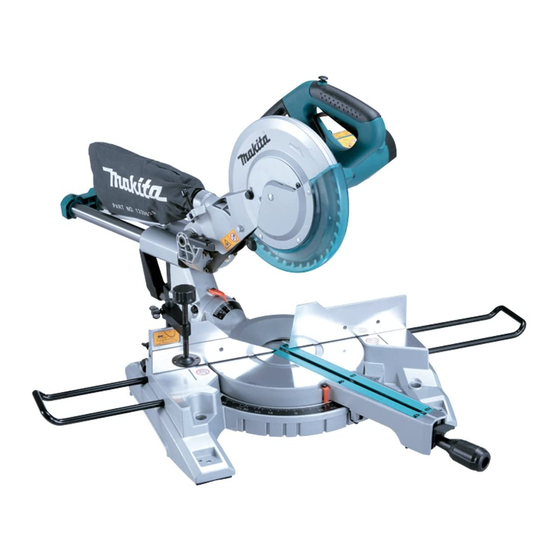
Models LS1017L and LS1018L are developed as more cost-competitive
255/ 260mm (10"/ 10-1/4") Slide compound saws.
The specification differences between both models are:
LS1017L: Bevel range of 45 degrees left and 5 degrees right
LS1018L: Bevel range of 45 degrees left and right
Additionally, both models are equipped with laser marker for easy trace
of cutting line.
S
pecification
Voltage (V)
110
120
220
230
240
Model No.
Diameter
Saw blade:
mm (")
Hole diameter
No load speed: min-
Electric brake
Electronic
Soft start
control
Constant speed
Laser marker
Lock-off switch
Protection against electric shock
Cord length: m (ft)
Weight according to
EPTA-Procedure 01/2003: kg (lbs)
*
Uses dry-cell battery as the power source.
1
*
with TCT saw blade and "Blocking mechanism at the rest position"
2
*
with TCT saw blade
3
See next page for the cutting capacity.
S
tandard equipment
Vertical vise ...................... 1 pc
Dust bag ............................ 1 pc
Triangular rule .................. 1 pc
Note: The standard equipment for the tool shown above may vary by country.
O
ptional accessories
Holder set
TCT saw blades
LS1017L, LS1018L
Slide Compound Saw 255mm (10")/ 260mm (10-1/4")
Current (A)
Cycle (Hz)
13.6
50/ 60
13.0
50/ 60
6.8
50/ 60
6.5
50/ 60
6.3
50/ 60
European countries:
= rpm
1
European countries*
Other countries*
TCT saw blade .................................... 1 pc
Socket wrench (with Hex wrench) ....... 1 pc
Holder set ............................................. 2 pcs
Horizontal vise
Holder assembly
Stand set
Continuous Rating (W)
Input
1,430
---
1,430
1,430
1,430
LS1017L
255 (10) - 260 (10-1/4)
, North America:
30 (1-3/16)
4,200
Yes
Yes
No
Yes*
Yes
Double insulation
2.5 (8.2)
: 19.5 (43.0),
2
: 19.5 (42.9)
3
[Illustrated above is LS1018L.]
Dimensions: mm (")
Model No.
LS1017L
Length (L)
Width (W)
Height (H)
581 (22-7/8)
Max. Output (W)
Output
---
---
---
---
---
LS1018L
, Other countries:
15.88 (5/8)
4,300
1
European countries*
: 19.9 (43.9),
2
Other countries*
: 19.8 (43.5)
3
PRODUCT
P 1/ 2
H
LS1018L
633 (25)
---
---
---
---
---
25.4 (1)
Table of Contents

Related Manuals for Makita LS1017L


Summary of Contents for Makita LS1017L
- Page 1 255/ 260mm (10"/ 10-1/4") Slide compound saws. The specification differences between both models are: [Illustrated above is LS1018L.] LS1017L: Bevel range of 45 degrees left and 5 degrees right LS1018L: Bevel range of 45 degrees left and right Dimensions: mm (") Model No.
- Page 2 P 2/ 2 pecification (cont.) [Cutting Capacities] North America Cutting capacities [Height x Width in mm (")] with 255mm (10") saw blade Bevel angle 45 degrees right 45 degrees left 0 degree (LS1018L only) Miter angle 50 x 305 91 x 305 31 x 305 0 degree (2 x 12)
- Page 3 REPAIR MANUAL Slide Compound Miter Saw LS1018L...
-
Page 4: Table Of Contents
CONTENTS P 1/ 45 [1] NECESSARY REPAIRING TOOLS .................2 [2] LUBRICATION .........................2 [3] DISASSEMBLY/ASSEMBLY -1. Switch ..........................5 -2. Starter..........................7 -3. Rotor..........................11 -4. Gear box........................12 -5. Gear lock pin.........................16 -6. Lower blade guard .......................17 -7. Link..........................18 -8. Up blade guard ......................20 -9. -
Page 5: Necessary Repairing Tools
[2] LUBRICATION Apply lubricant to the portions designated with the following arrows to protect parts and product from unusual abrasion. Arrow Type of lubricant Amount Makita grease SG No.0 approx. 10 g Makita grease N No.1 a little Liquid gasket... - Page 6 P 3/ 45 epair [2] LUBRICATION (cont.) Support arm section Support arm 90 degree block Friction ring Working table Locking rod Fig. 2 Up blade guard section Sealing ring Pin cap Up blade guard bracket Pin C Torsion spring Up blade guard Connection shaft Location tube Fig.
- Page 7 P 4/ 45 epair [2] LUBRICATION (cont.) Base section Base Friction plate Fig. 4 Lower blade guard section Bowl plate Hex bolt for guard Guard fix plate Guard spring Fig. 5 Link section Link sleeve Link Fig. 6...
-
Page 8: Disassembly/Assembly
P 5/ 45 epair [3] DISASSEMBLY/ASSEMBLY [3] -1. Switch DISASSEMBLING (1) Remove two Carbon brushes. And unscrew two M4x12 Cross head screws to remove Lock lever. Screw cap M4x12 Cross head screw Carbon brush Lock lever Lock lever Up blade guard Fig. - Page 9 P 6/ 45 epair [3] DISASSEMBLY/ASSEMBLY [3] -1. Switch (cont.) DISASSEMBLING (4) Unscrew eight M4x16 Tapping screws and remove Left handle. Right handle Motor housing Left handle Motor housing M4x16 Tapping screw Fig. 10 (5) Remove Brake system switch key, Switch lock bracket, Switch lock plate and Switch handle when exchanging the Switch. Brake system switch key Be careful that the spring Brake system switch...
-
Page 10: Starter
P 7/ 45 epair [3] DISASSEMBLY/ASSEMBLY [3] -1. Switch (cont.) ASSEMBLING (2) Attach Switch lock bracket to Right handle. Set Switch lock bracket so that its protrusion is between the rib on Handle L and Switch handle. Brake system switch key Right handle Switch lock bracket Brake system switch... - Page 11 P 8/ 45 epair [3] DISASSEMBLY/ASSEMBLY [3] -2. Starter (cont.) DISASSEMBLING Remove Baffle ring from Motor housing. Baffle ring Pull out Baffle ring. Motor housing Fig. 16 Disconnect the terminal connected to Carbon brush house with 1R173 or a similar tool such as long-nose pliers. 1R173 If it’s hard to disconnect, remove the connecting...
- Page 12 P 9/ 45 epair [3] DISASSEMBLY/ASSEMBLY [3] -2. Starter (cont.) DISASSEMBLING Unscrew two M5x70 tapping screws and remove Stator by tapping Motor housing with a resin hammer. Stator Resin hammer Motor housing M5x70 tapping screw Point can be tapped. Fig. 19 ASSEMBLING (1) Assemble Stator to Motor housing.
- Page 13 P 10/ 45 epair [3] DISASSEMBLY/ASSEMBLY [3] -2. Starter (cont.) ASSEMBLING (3) Connect Terminal to Carbon brush house with 1R173 or a similar tool such as long-nose pliers. Put the terminal in the notch. Be careful not to deform the terminal. Terminal Terminal Stator...
-
Page 14: Rotor
P 11/ 45 epair [3] DISASSEMBLY/ASSEMBLY [3] -3. Rotor DISASSEMBLING (1) Unscrew two M5x18 Cross head screws and remove Reference Rotor from Gear box. Bearing 6003 Rotor Bearing 6001 Gear box Rotor M5x18 Cross head screw Fig. 24 Fig. 25 (2) Remove Retaining ring 16 from Rotor with 1R291. -
Page 15: Gear Box
P 12/ 45 epair [3] DISASSEMBLY/ASSEMBLY [3] -3. Rotor (cont.) ASSEMBLING (3) Insert Rotor into Gear box. And fasten the Shaft fix cover with two M5x18 Cross head screws. Shaft fix cover Rotor Gear box Bearing 6003 When inserting Rotor, be careful of the position of Shaft fix cover. - Page 16 P 13/ 45 epair [3] DISASSEMBLY/ASSEMBLY [3] -4. Gear box (cont.) DISASSEMBLING (4) Unscrew two M4x10 Countersunk head bolts and (5) Remove Retaining ring 14 with 1R291. remove Bearing press plate. 1R291 Retaining ring 14 Bearing press plate M4x10 Countersunk head bolt Fig.
- Page 17 P 14/ 45 epair [3] DISASSEMBLY/ASSEMBLY [3] -4. Gear box (cont.) DISASSEMBLING Reference Bearing press plate M4x10 Countersunk head bolt M6x15 Countersunk head bolt Output shaft Shaft washer Output shaft ring 15.88 Bearing 6004 Bearing cover Gear Retaining ring 14 Fig.
- Page 18 P 15/ 45 epair [3] DISASSEMBLY/ASSEMBLY [3] -4. Gear box (cont.) ASSEMBLING (3) Fix Bearing press plate with two M4x10 Countersunk (4) Set Gear to Output shaft. head bolts. Output shaft Bearing press plate Gear M4x10 Countersunk head bolt Fig. 44 Fig.
-
Page 19: Gear Lock Pin
P 16/ 45 epair [3] DISASSEMBLY/ASSEMBLY [3] -5. Gear lock pin DISASSEMBLING (1) Remove Retaining ring 10.5x1 with a small slotted Reference screwdriver. Gear lock pin Gear lock pin Retaining ring 10.5x1 Gear box Small slotted screwdriver Gear lock spring Retaining ring 10.5x1 Fig. -
Page 20: Lower Blade Guard
P 17/ 45 epair [3] DISASSEMBLY/ASSEMBLY [3] -6. Lower blade guard DISASSEMBLING (1) Unscrew M6 Locknut and remove Lower blade guard. M6x12 Square neck bolt Lower blade guard Guard spring M6 Locknut Guard fix plate Bowl plate Fig. 53 ASSEMBLING (1) Set Guard spring to Lower blade guard. -
Page 21: Link
P 18/ 45 epair [3] DISASSEMBLY/ASSEMBLY [3] -7. Link DISASSEMBLING Fig. 53 (1) Remove Lower blade guard. (See (2) Fix Up blade guard at the top dead point by pressing Pin C. And, remove M6x20 H.S.bolt with glue. Up blade guard Link Pin C M6x20 H.S.bolt with glue... - Page 22 P 19/ 45 epair [3] DISASSEMBLY/ASSEMBLY [3] -7. Link (cont.) ASSEMBLING (1) Set Link to Up blade guard. And put Thin flat washer 6 into Pin and fix Link with Retaining ring 5 using a tool such as long-nose pliers. Up blade guard Retaining ring 5 Link...
-
Page 23: Up Blade Guard
P 20/ 45 epair [3] DISASSEMBLY/ASSEMBLY [3] -8. Up blade guard DISASSEMBLING (1) To release Power supply cord, unscrew two M4x18 Cross head screws and two Cord clamps. Cord clamp Cord clamp Power supply cord M4x18 Cross head screw Fig. 61 (2) (If not removing Motor housing and Gear box) Fix Up blade guard with Pin C at the lower dead point. - Page 24 P 21/ 45 epair [3] DISASSEMBLY/ASSEMBLY [3] -8. Up blade guard (cont.) DISASSEMBLING (1) Fix Up blade guard with Pin C at the top dead point. (2) And, remove Connection shaft with a plastic hammer And, loosen M6x15 H.S. screw to release the tension and 1R243.
- Page 25 P 22/ 45 epair [3] DISASSEMBLY/ASSEMBLY [3] -8. Up blade guard (cont.) ASSEMBLING (1) Set Torsion spring with Location tube inside, and set (2) Set Up blade guard at the lower dead point and fix Connection shaft and tap it with a plastic hammer. Connection shaft with two M6x12 Lock screws.
-
Page 26: Support Arm
P 23/ 45 epair [3] DISASSEMBLY/ASSEMBLY [3] -9. Support arm DISASSEMBLING (1) Unscrew four Cross head screws and remove Sliding bar rear cover. Sliding bar rear cover M5x15 Cross head screw M5x12 Cross head screw Fig. 75 Note Reference If Sliding bar rear cover can not be removed easily, Support arm tap it with a plastic hammer as shown below. - Page 27 P 24/ 45 epair [3] DISASSEMBLY/ASSEMBLY [3] -9. Support arm (cont.) DISASSEMBLING (4) Unscrew M4x12 Cross head screw and remove (5) Remove Hex nut. Bevel pointer. Hex nut Fig. 81 Bevel pointer M4x12 Cross head screw Fig. 80 (6) Remove two Big flat washer 10x26x2.5, Surface bearing (7) Remove M10 Locknut.
- Page 28 P 25/ 45 epair [3] DISASSEMBLY/ASSEMBLY [3] -9. Support arm (cont.) DISASSEMBLING (10) Remove Retaining ring 10 with 1R291. (11) Remove Flat washer 12x20x1, 90° block spring and 90° block. 90° block 90° block spring 1R291 Retaining ring 10 Flat washer 12x20x1 Fig.
- Page 29 Locking rod Support arm side. When assembling, be sure to clean Friction ring and around it. And apply Makita grease N No.1 a little on Friction ring. Fig. 91 (4) Temporarily attach Bevel pointer with M4x12 Cross (5) Insert Sliding bar into Support arm.
- Page 30 P 27/ 45 epair [3] DISASSEMBLY/ASSEMBLY [3] -9. Support arm (cont.) ASSEMBLING Adjustment With Motor housing and blade are attached, adjust tightening force of M10 Locknut so that the body wouldn't fall down at inclination of 10° and fall down at inclination of 25°. M10 Locknut Bevel scale Should not fall down...
-
Page 31: Working Table And Base
P 28/ 45 epair [3] DISASSEMBLY/ASSEMBLY [3] -10. Working table and Base DISASSEMBLING (1) Remove Sub fence and Right sub fence by loosening (2) Remove four M8x30 Hex bolts and remove Rip fence. three M10 Locknut. Right sub fence Sub fence Rip fence M10 Locknut M10 Locknut... - Page 32 P 29/ 45 epair [3] DISASSEMBLY/ASSEMBLY [3] -10. Working table and Base (cont.) DISASSEMBLING (7) Remove Pivot shaft by tapping it with a plastic hammer. (8) Remove two Friction plates. Friction plate Pivot shaft Plastic hammer Fig. 107 Fig. 108 (9) Remove Miter locking handle by turning it (10) Remove Lock shaft A.
- Page 33 P 30/ 45 epair [3] DISASSEMBLY/ASSEMBLY [3] -10. Working table and Base (cont.) ASSEMBLING (1) Set Lock spring and Lock pin to Lock shaft B and (2) Press Lock shaft B in the direction of the arrow attach to Working table. as shown below and set Press plate.
- Page 34 P 31/ 45 epair [3] DISASSEMBLY/ASSEMBLY [3] -10. Working table and Base (cont.) ASSEMBLING (5) Insert Pivot shaft to Working table with a plastic hammer. (6) Set two Friction plates to Working table. Plastic hammer Friction plate Working table Insert the protrusions Working table Pivot shaft on Friction plate...
-
Page 35: Preparation For Adjustment
P 32/ 45 epair [4] ADJUSTMENT [4] -1. Preparation for adjustment Adjust Bevel locking handle as shown below to make it to be shifted by hand. When Blade is fixed When adjusting Fig. 126 [4] -2. Adjustment Adjustment can be carried out following the procedure. Adjustment for 90°... -
Page 36: Adjustment For 45° Angle
P 33/ 45 epair [4] ADJUSTMENT [4] -2. Adjustment Adjustment for 45° angle (1) Set blade to the lower dead point and fix it with Pin C. (2) Remove Sub fence and Right sub fence. (3) Set 1R207 in the position as shown below and adjust until the gap between blade and 1R207 is cleared. (e.g.1) (e.g.2) 1R207... -
Page 37: Rip Fence
P 34/ 45 epair [4] ADJUSTMENT [4] -2. Adjustment Rip fence (1) Remove Sub fence and Right sub fence. (2) Loosen four M8x30 Hex bolts. And is the supporting point for adjustment. Adjust Rip fence so that the angle between blade and Rip fence is 90°. Rip fence 1R208 Blade... -
Page 38: Adjustment For Laser Light
P 35/ 45 epair [4] ADJUSTMENT [4] -2. Adjustment Adjustment for laser light (1) Draw a line (right angle to Rip fence) on plywood. (2) Align blade with the line. Table insert Blade Plywood Draw a line. Fig. 132 Fig. 133 (3) If blade cannot be aligned with the line, adjust the following settings. - Page 39 P 36/ 45 epair [4] ADJUSTMENT [4] -2. Adjustment Adjustment for laser light The other case Loosen H.S bolt. Loosen H.S bolt. Set M4x12 H.S.bolt in the center Set M4x12 H.S.bolt in the center Set M4x12 H.S.bolt in the center Set M4x12 H.S.bolt in the center on Laser moving fix plate on Laser moving fix plate...
-
Page 40: Circuit Diagram, Wiring Diagram
P 37/ 45 epair [5] Circuit diagram, Wiring diagram [5] -1. 220-240V area where Radio Interference Suppression is required [5] -1. 1. Circuit diagram Stator AssemblyColor index of lead wires' sheath Black Blue Gray Brown Carbon brush... - Page 41 P 38/ 45 epair [5] Circuit diagram, Wiring diagram [5] -1. 220-240V area where Radio Interference Suppression is required [5] -1. 2. Wiring diagram Overall wiring diagram Brake system switch Terminal block Electric switch Cord clamp Note: Do not route the wires over the housing because the wires may be pinched.
-
Page 42: How To Connect Wires
P 39/ 45 epair [5] Circuit diagram, Wiring diagram [5] -1. 220-240V area where Radio Interference Suppression is required [5] -1. 3. How to connect wires Electric switch (1) Red ..Stator assembly (2) Gray ..Carbon brush holder Soft starter C Black .. -
Page 43: Area Where Radio Interference Suppression Is Required
P 40/ 45 epair [5] Circuit diagram, Wiring diagram [5] -2. 110V area where Radio Interference Suppression is required [5] -2. 1. Circuit diagram Stator AssemblyColor index of lead wires' sheath Black Blue White Brown Carbon brush... -
Page 44: Circuit Diagram 2. Wiring Diagram
P 41/ 45 epair [5] Circuit diagram, Wiring diagram [5] -2. 110V area where Radio Interference Suppression is required [5] -2. 2. Wiring diagram Overall wiring diagram Terminal block Brake system switch Cord clamp Electric switch Note: Do not route the wires over the housing because the wires may be pinched. -
Page 45: How To Connect Wires
P 42/ 45 epair [5] Circuit diagram, Wiring diagram [5] -2. 110V area where Radio Interference Suppression is required [5] -2. 3. How to connect wires Electric switch (1) Red ..Stator assembly (2) Black ..Carbon brush holder Soft starter C Black .. -
Page 46: Area
P 43/ 45 epair [5] Circuit diagram, Wiring diagram [5] -3. 110V area [5] -3. 1. Circuit diagram Stator AssemblyColor index of lead wires' sheath Black White Carbon brush Soft starter (2) Electric switch Power supply Terminal block (Power supply line) cord... -
Page 47: Circuit Diagram 2. Wiring Diagram
P 44/ 45 epair [5] Circuit diagram, Wiring diagram [5] -3. 110V area [5] -3. 2. Wiring diagram Overall wiring diagram Terminal block Cord clamp Electric switch Note: Do not route the wires over the housing because the wires may be pinched. Motor housing complete Fig. -
Page 48: How To Connect Wires
P 45/ 45 epair [5] Circuit diagram, Wiring diagram [5] -3. 110V area [5] -3. 3. How to connect wires Electric switch (1) Red ..Stator assembly (2) Black ..Carbon brush holder Soft starter C (3) Black ..Terminal block 4 (Power supply line) Fig.