Motorola MC9500-K User Manual
Hide thumbs
Also See for MC9500-K:
- User manual (258 pages) ,
- Integrator manual (188 pages) ,
- Accessories manual (12 pages)

Related Manuals for Motorola MC9500-K


Summary of Contents for Motorola MC9500-K
- Page 1 MC9500-K MOBILE COMPUTER USER GUIDE...
- Page 3 MC9500-K Mobile Computer User Guide 72E-118501-03 Rev. B July 2011...
- Page 4 Motorola. No right to copy a licensed program in whole or in part is granted, except as permitted under copyright law. The user shall not modify, merge, or incorporate any form or portion of a licensed program with other program material, create a derivative work from a licensed program, or use a licensed program in a network without written permission from Motorola.
-
Page 5: Revision History
Revision History Changes to the original manual are listed below: Change Date Description -01 Rev. A 09/02/09 Initial release. -02 Rev. A 05/15/10 Add support for new memory configurations and Windows Mobile 6.5.3. -03 Rev. A 06/28/10 Add support for MC959B-K configuration. -03 Rev. - Page 6 MC9500-K Mobile Computer User Guide...
-
Page 7: Table Of Contents
Related Documents ..........................xviii Service Information..........................xviii Chapter 1: Getting Started Introduction ............................1-1 Unpacking ............................1-1 Part of the MC9500-K .......................... 1-2 Getting Started ............................. 1-3 Installing a microSD Card ......................1-3 Version 1 ..........................1-3 Version 2 ..........................1-4 Installing the SIM Card ........................ - Page 8 Introduction ............................2-1 Battery Functionality ..........................2-1 Battery Health ..........................2-2 Battery Status ............................2-3 Installed in an MC9500-K ....................... 2-3 In a Charger ........................... 2-5 Stand-alone ............................ 2-8 Charging the MC9500-K ........................2-9 Charging a Spare Battery ........................2-11 Charging Temperature ........................
- Page 9 Table of Contents Chapter 4: Data Capture Introduction ............................4-1 Laser Scanning ............................ 4-1 Scanning Considerations ....................... 4-1 Laser Scanning ..........................4-2 Decode Zones ..........................4-3 Imaging ..............................4-5 Operational Modes ......................... 4-6 Imager Scanning ..........................4-6 Imager Decode Ranges ......................... 4-8 Color Digital Camera ...........................
- Page 10 MC9500-K Mobile Computer User Guide Deleting All Call History Items ....................5-18 Viewing Call Status ........................5-18 Using the Call History Menu ....................5-19 Swapping Calls on an MC9596 ......................5-20 Swapping Calls on an MC9598 ......................5-20 Conference Calling on an MC9596 ...................... 5-21 Three-way Calling on an MC9598 .......................
- Page 11 Introduction ............................8-1 Universal Accessory System ....................... 8-3 Single Bay USB Cradle ........................8-4 Communication and Charging the MC9500-K Battery ..............8-4 Single Slot Battery Charger ......................... 8-6 Charging the Battery ........................8-6 Four Bay Charge Only Cradle ......................8-7 Charging ............................
- Page 12 Link LED ..........................8-10 Four Slot Battery Charger ........................8-11 Battery Charging ..........................8-11 Vehicle Cradle ............................. 8-12 Charging the MC9500-K Battery ....................8-12 Vehicle Battery Charger ........................8-13 Charging the Battery ........................8-13 Magnetic Stripe Reader ........................8-14 Attaching and Removing the MSR ....................8-14 Using the MSR ..........................
- Page 13 Start Screen ........................... D-8 Speaker Icon ..........................D-14 Battery Icons ..........................D-14 Connectivity Icon ..........................D-14 Locking the MC9500-K ........................D-15 Microsoft Locking ........................... D-15 Password Locking .......................... D-16 Using the RS507 Hands-free Imager ....................D-18 Removing the Battery .......................... D-18 Battery Removal ..........................
- Page 14 MC9500-K Mobile Computer User Guide Index...
-
Page 15: About This Guide
Documentation Set The documentation set for the MC9500-K provides information for specific user needs, and includes: MC9500-K Quick Start Guide - describes how to get the MC9500-K mobile computer up and running. • MC9500-K Mobile Computer User Guide - describes how to use the MC9500-K mobile computer. -
Page 16: Configurations
MC9500-K Mobile Computer User Guide Configurations This guide covers the following configurations: Data Capture Operating Configuration Radios Display Memory Keypads Options System MC9590 WLAN: 802.11 a/b/g 3.7” VGA 128 MB RAM/ 1D laser Windows See Keypads ® WPAN: Bluetooth Color... - Page 17 Tap Start > Settings > System tab > System Info icon > System tab. BTExplorer Software BTExplorer application is only available when the StoneStreet One Bluetooth stack is enabled. Refer to NOTE the MC9500-K Mobile Computer Integrator Guide for information on selecting the Bluetooth stack.
- Page 18 MC9500-K Mobile Computer User Guide To determine the BTExplorer software version: icon > > > BTExplorer Show BTExplorer File About Fusion Software To determine the Fusion software version: Tap Fusion Signal Strength icon > Wireless Status > Versions. Phone Software To determine the Phone software version: On MC9596-K, tap Start >...
-
Page 19: Chapter Descriptions
Chapter Descriptions Topics covered in this guide are as follows: provides information on getting the MC9500-K up and running for the first time. • Chapter 1, Getting Started provides information on the types of batteries and how to charge them. -
Page 20: Related Documents
For the latest version of this guide and all guides, go to: http://www.motorola.com/enterprisemobility/manuals. Service Information If you have a problem with your equipment, contact Motorola Enterprise Mobility support for your region. Contact information is available at: http://www.motorola.com/enterprisemobility/contactsupport. When contacting Enterprise Mobility support, please have the following information available: Serial number of the unit (found on manufacturing label) •... - Page 21 • Manufacturing Label Motorola responds to calls by email, telephone or fax within the time limits set forth in support agreements. If your problem cannot be solved by Motorola Enterprise Mobility Support, you may need to return your equipment for servicing and will be given specific directions. Motorola is not responsible for any damages incurred during shipment if the approved shipping container is not used.
- Page 22 MC9500-K Mobile Computer User Guide...
-
Page 23: Chapter 1 Getting Started
Inspect the equipment for damage. If any equipment is missing or damaged, contact the Motorola Enterprise Mobility Support center immediately. See for contact information. page xviii Prior to using the MC9500-K for the first time, remove the protective shipping film that covers the keypad and battery display. -
Page 24: Part Of The Mc9500-K
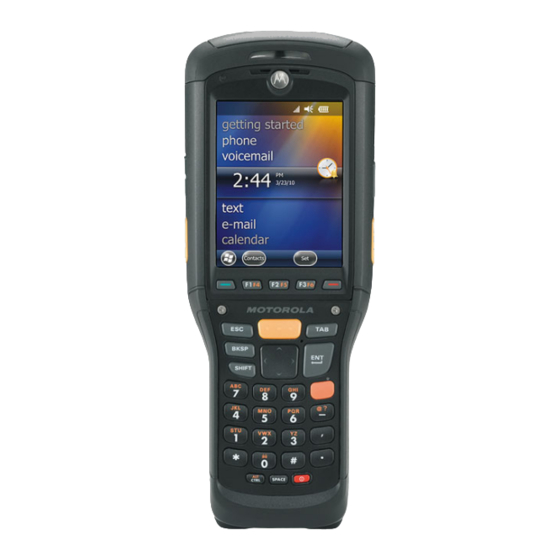
1 - 2 MC9500-K Mobile Computer User Guide Part of the MC9500-K Touch Screen with Protective Overlay Function Keys Volume Microphone Up/Down Button Scan Button Modular Keypad (Alpha Primary Keypad Shown) Power Button Battery Release Latch Battery Handstrap Speaker Camera (Optional) -
Page 25: Getting Started
ESD mat and ensuring that the operator is properly grounded. NOTE The MC9500-K was manufactured with two types of microSD card holders. In Version 1, the microSD card is placed in the holder door and the door closed and locked into place. -
Page 26: Version 2
1 - 4 MC9500-K Mobile Computer User Guide microSD Card Holder Door Lift microSD Card Holder Door Figure 1-3 Insert the microSD card into card holder door ensuring that the card slides into the holding tabs on each side of the door. -
Page 27: Installing The Sim Card
Getting Started 1 - 5 microSD Card Holder Door Lift microSD Card Holder Door Figure 1-6 Place the microSD card onto the contacts. microSD card Insert microSD Card in Holder Figure 1-7 Close the card holder door and slide to the right to lock into place. Align the SD card cover over the access hole and press down until it snaps into place. - Page 28 1 - 6 MC9500-K Mobile Computer User Guide SIM Card Cover Removal Figure 1-8 Slide the SIM card holder door to the left to unlock. Lift the SIM card holder door. Lifting the SIM Cover Figure 1-9 Insert the SIM card, as shown in...
-
Page 29: Installing The Battery
Battery Safety Guidelines on page 9-2. Before using the MC9500-K for the first time, charge the battery using either a charging cable or a cradle: For cable and cradle setup and charging procedures refer to the MC9500-K Series Mobile NOTE Computer Integrator Guide. - Page 30 The MC9500-K is equipped with a memory backup battery which automatically charges from the fully-charged main battery. When using the MC9500-K for the first time, the backup battery requires approximately 36 hours to fully charge. This is also true any time the backup battery is discharged, which occurs when the main battery is removed for several hours.
-
Page 31: Charging Temperature
Table 1-1. Powering On the MC9500-K After the MC9500-K is connected to power the splash screen displays for about a minute as the MC9500-K initializes its flash file system, then the calibration window appears. Calibrating the Screen NOTE The Calibration screen can be accessed by pressing CTRL key - BKSP key or tapping Start > Settings >... -
Page 32: Removing The Microsd Card
Figure 1-12 Lift the battery from the MC9500-K. Insert the replacement battery, top first, into the battery compartment in the back of the MC9500-K. Press the battery down until the battery release latches snap into place. The MC9500-K powers up after inserting the battery. -
Page 33: Removing The Sim Card
Getting Started 1 - 11 Removing the SIM Card To remove an SIM card: Suspend the MC9500-K prior to removing the battery. Failure to properly remove the battery may cause CAUTION the MC9500-K to cold boot and potential loss of data. - Page 34 1 - 12 MC9500-K Mobile Computer User Guide...
-
Page 35: Chapter 2 Battery Management
Battery Functionality The 4800 mAh battery provides power to the MC9500-K and contains charging and status indications on the front of the battery. The indicators function differently depending upon the battery mode and allow the user to determine the health of the battery. -
Page 36: Battery Health
The Battery Usage Threshold value can be changed. See the MC9500-K Mobile Computer Integrator Guide for more information. When the battery becomes unhealthy, a dialog box displays on the MC9500-K. When this appears, tap Dismiss. Replace the battery as soon as possible. The battery Charge Level indicator display an “X” when the battery becomes unhealthy (see 2-3). -
Page 37: Battery Status
The Charge Level indicator does not display the charge level while the MC9500-K is charging. NOTE When the 4800 mAh battery is installed in the MC9500-K, the user can view the charge level (with Status button press) and health of the battery (see 2-4). - Page 38 Indicates that the remaining charge is approximately between 81% and 100%. The battery front panel is not visible when the MC9500-K is charging in a cradle. The battery front NOTE panel is visible when charging with a charging cable. The Charge Level indicator displays a “charging in mobile computer”...
-
Page 39: In A Charger
Button Charging Press in cradle or cable The health of the battery can also be viewed on the MC9500-K Power applet. Tap Start > Settings > Power icon > BatteryMgmt tab. Power - BatteryMgmt Window Figure 2-5 BatteryMgmt Window Table 2-3... - Page 40 2 - 6 MC9500-K Mobile Computer User Guide Battery Status LED Charge Level Indicator Battery in Single Slot Battery Charger Figure 2-6 The Battery Status LED displays the current state of charging as described in 2-4. The Charge Level Table...
- Page 41 Battery Management 2 - 7 Battery Status in Charger Table 2-4 Healthy Battery Unhealthy Battery Battery Status Charge Level Battery Status Charge Level State Indicator Indicator None (charger not powered) Charging Slow Blinking Slow Blinking Red Amber (1 blink every 2 (1 blink every 2 seconds) seconds)
-
Page 42: Stand-Alone
Stand-alone When the battery is not installed in an MC9500-K or a charger, the charge status and health of the battery displays on the battery front panel. If the battery is unhealthy, an “X” appears in the Charge Level indicator. Press the Status button to view the health and charge level of the battery. -
Page 43: Charging The Mc9500-K
The MC9500-K is equipped with a memory backup battery which automatically charges from the fully-charged main battery. When using the MC9500-K for the first time, the backup battery requires approximately 36 hours to fully charge. This is also true any time the backup battery is discharged, which occurs when the main battery is removed for several hours. - Page 44 2 - 10 MC9500-K Mobile Computer User Guide Charging/Battery Status LED Indications (Continued) Table 2-6 Healthy Battery Unhealthy Battery State MC9500-K LED Status MC9500-K LED Status Fully Charged Solid Green Solid Red Charging Error Fast Blinking Amber Fast Blinking Amber...
-
Page 45: Charging A Spare Battery
Battery Management 2 - 11 Charging a Spare Battery Charge a spare battery using one of the following accessories: Single Slot Battery Charger • Four Slot Battery Charger • Vehicle Battery Charger. • To charge a spare battery: Ensure the charger is connected to an appropriate power source. Insert the spare battery into the charger. -
Page 46: Charging Temperature
Charge batteries in temperatures from 0°C to 40°C (32°F to 104°F). Note that charging is intelligently controlled by the MC9500-K. To accomplish this, for small periods of time, the MC9500-K alternately enables and disables battery charging to keep the battery at acceptable temperatures. The MC9500-K indicates when charging is disabled due to abnormal... -
Page 47: Power Saving Techniques
Battery Management 2 - 13 Power Saving Techniques Observe the following battery saving tips: Leave the MC9500-K connected to AC power at all times when not in use. • Set the MC9500-K to turn off after a short period of non-use. - Page 48 2 - 14 MC9500-K Mobile Computer User Guide To open Wireless Manager, tap the Connectivity icon or tap Wireless Manager on the Today screen. Connectivity icon Opening Wireless Manager Figure 2-8 Select Wireless Manager. Wireless Manager Window Figure 2-9 NOTE Wireless connection options vary depending upon configurations.
- Page 49 Battery Management 2 - 15 Wireless Manager Menu Figure 2-10...
- Page 50 2 - 16 MC9500-K Mobile Computer User Guide...
-
Page 51: Chapter 3 Using The Mc9500-K
Chapter 3 Using the MC9500-K Introduction This chapter explains the indicators, buttons, status icons, and controls on the MC9500-K, and provides basic instructions for using the device. LED Indicators The MC9500-K has three LED indicators. The Decode LED indicates scanning status. The Battery Status LED indicates battery charging and health status.The WAN Radio Status LED indicates WAN radio status. - Page 52 Slow Blinking Green WAN activity. No WAN activity. NOTE For information about scanning/decoding, see Capture. For information about WAN radio Chapter 4, Data status and settings, see Phone, or refer to the MC9500-K Mobile Computer Integrator Chapter 5, Using the Guide.
-
Page 53: Resetting The Mc9500-K
Resetting the MC9500-K There are two reset functions, warm boot and cold boot. A warm boot restarts the MC9500-K by closing all running programs. A cold boot also restarts the MC9500-K, and also initializes some drivers. Data saved in flash memory or a memory card is not lost. -
Page 54: Locking The Mc9500-K
D-15 You can lock the MC9500-K by disabling key presses and screen tap or by requiring a password. Keypad Locking Locking the MC9500-K turns off keyboard and touch screen functionality. This is helpful when the MC9500-K is turned on and you want to prevent accidental key presses. -
Page 55: Password Locking
Call on page 5-10 Password Locking Use the Password window to set a password to disable unauthorized access to the MC9500-K. If the device is configured to connect to a network, use a strong (difficult to figure out) password NOTE to help protect network security. - Page 56 Figure 3-6 In the text box, enter a hint for a password reminder. Tap ok. When the MC9500-K is not used for a period of time and the user tries to access the device, the Password window appears. Enter Password Windows Figure 3-7 Enter the password to un-lock the device.
-
Page 57: Keypads
Function Buttons The MC9500-K’s buttons perform certain functions. Power: Press the red Power button to place the MC9500-K into suspend mode or wake from suspend mode. • Also use the Power button to reset the MC9500-K by performing a warm or cold boot. See... -
Page 58: Entering Data
3 - 8 MC9500-K Mobile Computer User Guide Entering Data When entering data on the keypad, use either the single-hand method or the two-hand method as shown in Figure 3-8. Single-hand Method Two-hand Method Entering Data on the Keypad Figure 3-8... -
Page 59: Interactive Sensor Technology
It can also be used to keep the MC9500-K active while it is in movement to prevent it from quickly going into suspend mode while in use. -
Page 60: Free Fall Detection
IST continuously monitors gravitational force on the MC9500-K according to its current position. When the MC9500-K free falls, IST detects the absence of gravitational force and records the event data if it detects a free fall more than 450 ms, which may indicates nearly a one meter drop. This data can be used as an indicator of potential abuse or misuse. -
Page 61: Today Screen
Using the MC9500-K 3 - 11 Today Screen NOTE On devices with Windows Mobile 6.5.3, the Today screen has changed. See Home Screen on page D-1 more information. The Today screen displays important information, such as upcoming appointments and status indicators. Tap a section on the screen to open the associated program. -
Page 62: Status Icons
3 - 12 MC9500-K Mobile Computer User Guide Status Icons NOTE On devices with Windows Mobile 6.5.3,the functionality of the Status bar has changed. See Status Bar on for more information. page D-5 The Navigation bar at the top of the screen can contain the status icons listed in Table 3-3. - Page 63 Using the MC9500-K 3 - 13 Status Icons (Continued) Table 3-3 Icon Function Description Call missed. Dialing while no SIM card is installed. Voice call in progress. Calls are forwarded. Call on hold. Speakerphone is on. Antenna/signal icon: wireless on/good signal.
-
Page 64: Programs
Indicates the Bluetooth radio is connected to another Bluetooth device. (Displays only if the StoneStreet One Bluetooth stack is enabled) ActiveSync Indicates an active serial connection between the MC9500-K and the host computer. IST icon Opens the IST settings menu. - Page 65 Computer Integrator Guide for more information. AirBEAM Client Allows specially designed software packages to be transferred between a host server and the MC9500-K. Refer to the MC9500-K Series Mobile Computer Integrator Guide for more information. BT Information Displays information about the Bluetooth radio. See Chapter 7, Using Bluetooth.
- Page 66 SMS Staging Receives and processes SMS messages from an MSP SMS Staging - Server and allows the user to stage an MC9500-K based on them. Requires the purchase of an MSP client license per device. Task Manager Enables viewing of memory and CPU allocations and stops running processes.
-
Page 67: Settings
Play back audio and video files. Refer to the Microsoft Applications for Windows Mobile 6 User Guide for more information. Settings lists control applications pre installed on the MC9500-K. Tap Start > Settings to open the Settings Table 3-7 window. - Page 68 Set the appropriate GPS communication ports, if required. You may need to do this when there are programs on your device that access GPS data or you have connected a GPS receiver to the MC9500-K. GPS Setup View GPS & A-GPS SUPL information.
- Page 69 Windows Mobile 6 User Guide for more information. Regional Settings Set the regional configuration to use, including the format for displaying numbers, currency, date, and time on the MC9500-K. Refer to the Microsoft Applications for Windows Mobile 6 User Guide for more information.
-
Page 70: Adjusting Volume
Microsoft Applications for Windows Mobile 6 User Guide for more information. Wireless Manager Enables or disables the MC9500-K’s wireless radios and customizes Wi-Fi and Bluetooth and Phone settings. Adjusting Volume To adjust the system volume using the Speaker icon in the navigation bar: Tap the Speaker icon. -
Page 71: Battery Status Indications
Tap Start > Settings > System tab > Power icon. • Settings Power Window Figure 3-15 Battery Reserve Options If the charge of the battery reaches a critical threshold, the MC9500-K shuts down. This threshold can be changed but affects the amount of time that data can be retained. -
Page 72: Main Battery Temperature Notifications
The user should move to an environment within proper operating temperature. Level 2: Temperature Warning; this level is similar to main battery very low warning. It indicates the battery • temperature has reached the second threshold level. The user should stop using the MC9500-K. -
Page 73: Using Voice-Over-Ip
802.11b/g (2.4 GHz) band due to wireless interference. When using a Bluetooth headset with the MC9500-K and VoWLAN, it is required to use the Bluetooth Headset profile instead of Hands-free profile. Use the buttons on the MC9500-K to answer and end calls. See Chapter 7, for information on setting up a Bluetooth Headset Profile. -
Page 74: Infrared Connection
Switch to the program where you created the item you want to send and locate the item in the list. NOTE Do not cover or block the IrDA window. Align the IrDA port of the MC9500-K with that of the IrDA device so that they are unobstructed and within a close range. -
Page 75: Printing
Figure 3-21 To receive files via IrDA connection: Align the IrDA port of the MC9500-K with that of the other IrDA device so that they are unobstructed and within a close range. On the other device, send the file to the MC9500-K. - Page 76 3 - 26 MC9500-K Mobile Computer User Guide...
-
Page 77: Chapter 4 Data Capture
Imaging • Color digital camera. • NOTE To read a bar code, a scanning enabled application must be installed on the MC9500-K. A sample scanning application can be downloaded from the Motorola Support Central site at http://www.motorola.com/enterprisemobility/support. Laser Scanning An MC9500-K with an integrated linear laser scanner has the following features: Reading of a variety of bar code symbologies, including the most popular 1-D code types. -
Page 78: Laser Scanning
Figure 4-1 Press and hold the scan button. The laser beam exits from the end of the MC9500-K. Ensure the red scan beam covers the entire bar code. The Decode LED lights red to indicate that scanning is in process, then lights green and a beep sounds, by default, to indicate the bar code was decoded successfully. -
Page 79: Decode Zones
1.70 24.50 20 mil 25.50 2.00 40 mil 27.50 55 mil 31.50 76.2 88.9 12.7 25.4 38.1 50.8 63.5 Depth of Field * Minimum distance determined by symbol length and scan angle. MC9500-K Laser Scanner 35° Decode Zone Figure 4-3... - Page 80 24.50 20 mil 28.50 1.25 40 mil 30.50 55 mil 34.50 25.4 50.8 63.5 88.9 101.6 12.7 38.1 76.2 Depth of Field * Minimum distance determined by symbol length and scan angle. MC9500-K Laser Scanner 47° Decode Zone Figure 4-4...
-
Page 81: Imaging
4. Dependent on width of bar code. 5. Distances measured from front edge of device. Imaging MC9500-K with an integrated imager have the following features: Omnidirectional (360°) reading of a variety of bar code symbologies, including the most popular linear, postal, •... -
Page 82: Operational Modes
This feature is ideal for pick lists containing multiple bar codes and manufacturing or transport labels containing more than one bar code type (either 1D or 2D). Image Capture Mode: Use this mode to capture an image within the MC9500-K’s field of view. This is useful •... - Page 83 Pick List Mode with Multiple Bar Codes Figure 4-7 Release the scan button. NOTE Imager decoding usually occurs instantaneously. The MC9500-K repeats the steps required to take a digital picture (image) of a poor or difficult bar code as long as the scan button remains pressed.
-
Page 84: Imager Decode Ranges
4 - 8 MC9500-K Mobile Computer User Guide Imager Decode Ranges The decode ranges provide the decode distances for bar codes of specified densities. shows the imager Figure 4-8 decode ranges and lists the scan ranges for the selected bar code densities. The minimum Table 4-2 on page 4-9 element width (or “symbol density”) is the width in mils of the narrowest element (bar or space) in the symbol. -
Page 85: Color Digital Camera
1. Near distances are field-of-view (FOV) limited. 2. Contrast is measured as Mean Reflective Difference (MRD) at 670 nm. 3.Workingrangespecificationsattemperature=23°C,pitch=18°,roll=0°,skew=0°,photographicquality,ambient light ~30 ft.-c, humidity 45-70% RH. Color Digital Camera MC9500-K with an integrated color digital camera have the following features: Photo capture • Video capture •... -
Page 86: Taking Photos
Tap Camera on the command bar. Check the image on the view finder, adjust if necessary. Press the Enter key to take the picture. Hold the MC9500-K still until the shutter sound is heard. Recording Video NOTE Ensure that the scanning/imaging application is disabled prior to enabling the camera. -
Page 87: Viewing Photos And Videos
Data Capture 4 - 11 NOTE By default, the time limit for recording videos is set to 30 seconds. Press the Enter key to begin recording. Recording stops when you press the Enter button again. Viewing Photos and Videos To view photos and video clips: Tap Start >... - Page 88 4 - 12 MC9500-K Mobile Computer User Guide...
-
Page 89: Chapter 5 Using The Phone
NOTE Keypads vary depending on services and the state of the phone. On the MC959B, the phone dialer (keypad) is disabled. Access the keypad regardless of the program in use. Applications on the MC9500-K can be in use during a call. -
Page 90: Turning The Phone On And Off
To access the phone keypad tap Start > Phone, press the F1 key or press the green key. To receive calls when the MC9500-K is suspended, leave the phone radio turned on and ensure the MC9500-K is set to wake with any key. -
Page 91: Audio Modes
Audio Modes The MC9500-K offers three audio modes for use during phone calls: Handset Mode: Switches audio to the speaker at the top front of the MC9500-K, so you can use the • MC9500-K as a handset. This is the default mode. -
Page 92: Using A Bluetooth Headset
Chapter 7, Using Bluetooth NOTE When using a Bluetooth headset, during a call, the MC9500-K power button is disabled and the MC9500-K will not go into suspend mode. Once the call is completed, the power button functionality is enabled. -
Page 93: Adjusting Audio Volume
Using the Phone 5 - 5 WWAN Bluetooth Audio Notification Dialog Box Figure 5-5 Adjusting Audio Volume Use the Volume Control Slider or the keypad keys to adjust the volume of the ringer when not in a call and the audio volume when in a call. -
Page 94: Making A Call
To disable the HAC feature, tap the Disable HAC radio button. Making a Call NOTE You can make emergency calls even when the MC9500-K is locked or when a SIM card is not installed. See for more information. Making an Emergency Call on page 5-10 With the MC9500-K, you can make a call from the phone, contacts, speed dial and call history. -
Page 95: Creating An Outlook Contact
Using the Phone 5 - 7 Tap Call Work, Call Home or Call Mobile. NOTE To make a call from an open contact, tap the number to call. See On-Device Help for more information about Contacts. Creating an Outlook Contact NOTE When entering a contact phone number that contains a star (*) character followed by a plus (+) character, save the contact as an Outlook Contact. -
Page 96: Deleting A Contact
5 - 8 MC9500-K Mobile Computer User Guide Tap the contact in the contact list to open it. Tap Menu > Edit and make the changes. Tap ok. Deleting a Contact To delete a contact: Tap Start > Contacts. Tap and hold the contact in the contact list and select Delete Contact from the pop-up menu, or select the contact and tap Menu >... -
Page 97: Making A Speed Dial Call
Using the Phone 5 - 9 Phone icon Call History Figure 5-10 Tap the phone icon next to the number to begin dialing and return to the phone keypad. Tap End or press the red key to stop dialing or end the call. Making a Speed Dial Call Use Speed Dial to call someone saved in the speed dial directory. -
Page 98: Making An Emergency Call
Answering a Call A dialog box appears on the MC9500-K when it receives an incoming call. If the phone is set to ring, a ring tone sounds. Answer or ignore the incoming call. To answer an incoming call tap Answer on the Phone > Incoming... dialog or press the green key. -
Page 99: Smart Dialing
Using the Phone 5 - 11 If a caller isn't in your contact list, create a contact during the call or from Call History by tapping Menu > • Save to Contacts. To terminate a call when a second call comes in and answer the waiting call, tap End on the Phone keypad to •... -
Page 100: Muting A Call
5 - 12 MC9500-K Mobile Computer User Guide To make a call or send a text message using Smart Dialing: Begin entering the first few numbers or characters. In the Smart Dialing panel, use the up and down arrows on the keypad to navigate to the desired contact or phone number. -
Page 101: Using Speed Dial
Using the Phone 5 - 13 Note icon Call History - Notes Menu Figure 5-15 Tap View Note. Tap ok to exit. NOTE Also access notes directly from the Notes application by tapping Start > Programs > Notes. Using Speed Dial Create speed dial numbers to dial frequently called numbers with a single tap. - Page 102 5 - 14 MC9500-K Mobile Computer User Guide Speed Dial Contact Location Figure 5-17 In the Location field, tap the up/down arrows to select an available location to assign as the new speed dial entry. The first speed dial location is reserved for voice mail.
-
Page 103: Editing A Speed Dial Entry
Using the Phone 5 - 15 Speed Dial Contact Location Figure 5-19 Tap the up/down arrows to select an available location to assign as the new speed dial entry. The first speed dial location is reserved for voice mail. Tap ok. Editing a Speed Dial Entry Tap Start >... -
Page 104: Deleting A Speed Dial Entry
5 - 16 MC9500-K Mobile Computer User Guide Deleting a Speed Dial Entry Tap Start > Phone or press the green key. Tap Speed Dial. Tap and hold the contact name. Speed Dial Delete Menu Figure 5-21 Tap Delete. Tap Yes to confirm permanently deleting the speed dial entry. -
Page 105: Changing The Call History View
Using the Phone 5 - 17 Changing the Call History View Tap Start > Phone or press the green key to display the Phone keypad. From the Phone keypad, tap Call History. Tap Menu > Filter to show the menu. Call History - All Calls/Show Menu Figure 5-22 Select a view type from the menu to display only missed calls, outgoing calls, incoming calls, or calls listed... -
Page 106: Deleting Call History Items By Call Date
5 - 18 MC9500-K Mobile Computer User Guide Deleting Call History Items by Call Date Tap Start > Phone or press the green key to display the Phone keypad. From the Phone keypad, tap Call History. Tap Menu > Call Timers.. -
Page 107: Using The Call History Menu
Using the Phone 5 - 19 Call History - Detail Figure 5-26 NOTE When more than one call is on the phone line, only the duration of the first call is recorded. Tap ok and then ok to exit. Using the Call History Menu Use the Call History menu to dial voice mail, access the Activation Wizard, save to contacts, view a note, delete a listing, send an SMS, and make a call. -
Page 108: Swapping Calls On An Mc9596
5 - 20 MC9500-K Mobile Computer User Guide Swapping Calls on an MC9596 To move between two or more phone calls: Tap Start > Phone or press the green key to display the Phone keypad. Enter the first phone number and press Talk. When the call connects, Hold appears on the keypad. -
Page 109: Conference Calling On An Mc9596
Using the Phone 5 - 21 Answer a Call Figure 5-30 When a second call arrives, tap Answer. The first call is placed on hold. Tap Talk to swap from one call to the other. Call Swapping Figure 5-31 Tap End or press the red key to end active call. The remaining call re-connects, tap Answer to connect to the call. - Page 110 5 - 22 MC9500-K Mobile Computer User Guide Conference Call - Hold Figure 5-32 Tap Hold to place the first call on hold. Enter the second phone number and tap Talk. After the call is answered, tap Menu > Conference to place the calls in conference mode.
-
Page 111: Three-Way Calling On An Mc9598
Using the Phone 5 - 23 Creating a Private Call Figure 5-34 Three-way Calling on an MC9598 NOTE Three-way Calling may not be available on all services. Please check with your service provider for availability. To create a three-way phone session with two people and you as the initiator: Tap Start >... -
Page 112: Text Messaging
160 characters. Short text messages delivered over mobile networks transmit from the sending MC9500-K, are stored in a central short message center, then forwarded to the destination mobile device. If the recipient is not available, the message is stored and can be sent later. - Page 113 Using the Phone 5 - 25 Tap Start > Messaging > Text Messages, or on the Today screen, tap Text Messages. Tap Text Messages. Text Messaging on Today Screen Figure 5-38 The Text Messages window appears. Messaging Window Figure 5-39 In the message list, tap a text message.
-
Page 114: Sending A Text Message
5 - 26 MC9500-K Mobile Computer User Guide To reply, enter text in the reply field and tap Send. NOTE If the phone is turned off and you tried to call the sender, send a reply, or forward the message, you are prompted to turn the phone function on. - Page 115 Using the Phone 5 - 27 Message Options Window Figure 5-43 Tap Send when you've finished the message. If the phone is turned on, your text message is sent. If it’s off, you are prompted to turn on the phone. If you do so, the message is sent;...
-
Page 116: Establishing A Gsm Data Connection (Mc9596-K And Mc959B-K)
5 - 28 MC9500-K Mobile Computer User Guide Establishing a GSM Data Connection (MC9596-K and MC959B-K) NOTE Refer to the MC9500-K Series Mobile Computer Integrator Guide for information on configuring a data connection. On MC959B-K configurations, ensure that the correct carrier is configured appropriately on the Broadband Settings window. -
Page 117: Ending A Data Connection
Using the Phone 5 - 29 Data Connection Figure 5-45 Select Connect. Connecting Using GPRS Figure 5-46 If the SIM card is protected with a Personal Identification Number (PIN), a dialog box pops up requesting the appropriate PIN to unlock the SIM card. In this case, enter the PIN and tap ok. NOTE Place emergency calls at any time, without entering a PIN or a SIM card When a connection is established, launch Internet Explorer to browse the Internet or launch an applicable application. -
Page 118: Establishing An Cdma Data Connection (Mc9598-K And Mc959B-K)
5 - 30 MC9500-K Mobile Computer User Guide Connectivity Dialog Box Figure 5-47 Tap Disconnect. NOTE Tapping during an active data transfer (e.g., downloading a web page) automatically reconnects Disconnect the connection. You cannot disconnect the connection until the data transfer is complete Establishing an CDMA Data Connection (MC9598-K and MC959B-K) NOTE Ensure that you have data service activated with your service provider. -
Page 119: Ending A Data Connection
Using the Phone 5 - 31 Data Connection Figure 5-48 Ending a Data Connection To cancel a data connection in progress, tap Cancel in the Connecting... dialog window. To end an established data connection: to display the Connectivity dialog box. NOTE On devices with Windows Mobile 6.5.3, tap the Status Bar and then tap the Connectivity icon to display the Connectivity dialog box. - Page 120 5 - 32 MC9500-K Mobile Computer User Guide Select a carrier/network from the Select New Carrier drop-down list. Tap Switch. The message “Carrier switch starting…” appears as the new carrier firmware is downloaded to the radio. When the download is completed, the message “Upload Done” appears briefly.
-
Page 121: Chapter 6 Using Gps Navigation
WARNING When using the MC9500-K in a vehicle, it is the user’s responsibility to place, secure and use in a manner that will not cause accidents, personal injury or property damage or obstruct their view. It... -
Page 122: Operation
MC9500-K from receiving a GPS signal from satellites. To improve GPS signal strength, place the MC9500-K where there is a clear view of the sky. A direct line of sight is required between the MC9500-K and the GPS satellites to access information from the satellites. - Page 123 Using GPS Navigation 6 - 3 A-GPS follows the Secure User Plane Location (SUPL) protocol which allows a mobile device to communicate with a SUPL server. Refer to the EMDK Help file for information on setting up SUPL on the MC9500-K.
- Page 124 6 - 4 MC9500-K Mobile Computer User Guide...
-
Page 125: Chapter 7 Using Bluetooth
MC9500-K as a modem, create a dial-up modem connection between a computer and MC9500-K. The MC9500-K with Bluetooth technology uses either the StoneStreet Bluetooth stack or the Microsoft Bluetooth stack. To write an application that uses the StoneStreet One Bluetooth stack APIs, refer to the Enterprise Mobility Developer Kit (EMDK) Help. -
Page 126: Security
MC9500-K Mobile Computer User Guide The Bluetooth radio in this MC9500-K operates as a Class 2 device power class. The maximum output power is 2.5mW and the expected range is 32.8 feet (10 meters). A definition of ranges based on power class is difficult to obtain due to power and device differences, and whether one measures open space or closed office space. -
Page 127: Bluetooth Configuration
Computer Integrator Guide, Appendix B, for information on switching to the StoneStreet One Bluetooth stack. If the MC9500-K is configured to use the StoneStreet One Bluetooth stack, the Bluetooth icon appears at the bottom right corner of the Today screen. If the Microsoft Bluetooth stack is configured, the Bluetooth icon does not appear. -
Page 128: Bluetooth Power States
With StoneStreet One Bluetooth Stack Performing a cold boot on the MC9500-K turns off Bluetooth after initialization (which takes a few moments). It is normal to see the Bluetooth icon appear and disappear, as well as a wait cursor, when initialization proceeds in all modes. -
Page 129: Resume
Turn off the Bluetooth radio to save power or if entering an area with radio restrictions (e.g., an airplane). When the radio is off, other Bluetooth devices cannot see or connect to the MC9500-K. Turn on the Bluetooth radio to exchange information with other Bluetooth devices (within range). -
Page 130: Disabling Bluetooth
Discovering Bluetooth Device(s) The MC9500-K can receive information from discovered devices without bonding. However, once bonded, the MC9500-K and a bonded device exchange information automatically when you turn the Bluetooth radio on. See for more information. Bonding with Discovered Device(s) on page 7-34 To find Bluetooth devices in the area: Ensure that Bluetooth is enabled on both devices. - Page 131 Using Bluetooth 7 - 7 Searching for Bluetooth Devices Figure 7-4 Select a device from the list. Select a Bluetooth Device Figure 7-5 Tap Next. The Enter Passcode window appears. NOTE If Smart-pairing is configured and the device is requesting one of the pre-defined PINs, the Enter Passcode window does not appear.
-
Page 132: Available Services
After the passcodes have been accepted on both sides, you have a trusted (“paired”) connection. Available Services NOTE Some devices might not require a PIN. This depends upon the device’s authentication. The MC9500-K with Microsoft Bluetooth stack offers the following services: OBEX Object Push Services via Beam •... -
Page 133: Object Push Services Via Beam
Select Beam File. The MC9500-K searches for Bluetooth devices in the area. Tap Tap to send next to the Bluetooth device to send the file to. The MC9500-K communicates with the device and send the file. When completed, Tap to send changes to Done. -
Page 134: Internet Sharing
Select Send Contact > Beam. The MC9500-K searches for Bluetooth devices in the area. Tap Tap to send next to the Bluetooth device to send the file to. The MC9500-K communicates with the device and send the contact. When completed, Tap to send changes to Done. -
Page 135: Hands-Free Services
Refer to the headset user manual for more information. Only WAN audio is routed to the headset. System audio is still emitted through the MC9500-K speaker. You can accept calls and re-dial using the Hands-free profile. -
Page 136: Serial Port Services
Ensure that the two devices are within 30 feet (10 meters) of one another. Tap Start > Settings > Connections tab > Bluetooth icon > Devices tab. Tap Add new device. The MC9500-K begins searching for discoverable Bluetooth devices in the area. Select a device from the list. -
Page 137: Activesync Using Serial Port Services
Using Bluetooth 7 - 13 ActiveSync Using Serial Port Services Use the wireless Bluetooth serial port connection for ActiveSync just as you would a physical serial cable connection. You must configure the application that will use the connection to the correct serial port. To set up a Bluetooth ActiveSync connection: Before setting up a Bluetooth ActiveSync connection, configure the Bluetooth function of your device. -
Page 138: Phone Book Access Profile Services
To disconnect the ActiveSync connection, tap the ActiveSync icon on the Today screen. Tap Disconnect. Phone Book Access Profile Services Phone Book Access profile (PBAP) is used to synchronize contacts between a remote device and the MC9500-K. To establish an PBAP synchronization: Ensure that Bluetooth is enabled and discoverable on both devices. -
Page 139: Dial-Up Networking Services
If Yes is selected, contacts from the MC9500-K are transferred to the car kit. Dial-Up Networking Services Dial-up networking allows the user to connect a PC or laptop to the MC9500-K and use the MC9500-K as a modem to connect to an office network or ISP. - Page 140 7 - 16 MC9500-K Mobile Computer User Guide Tap Add new device. The MC9500-K begins searching for discoverable Bluetooth devices in the area. Select a stereo headset from the list. Tap Next. The Enter Passcode window appears. Refer to the device’s User Manuals for more information.
-
Page 141: Using Stonestreet One Bluetooth Stack
Turn off the Bluetooth radio to save power or if entering an area with radio restrictions (e.g., an airplane). When the radio is off, other Bluetooth devices cannot see or connect to the MC9500-K. Turn on the Bluetooth radio to exchange information with other Bluetooth devices (within range). -
Page 142: Wizard Mode
Discovering Bluetooth Device(s) The MC9500-K can receive information from discovered devices without bonding. However, once bonded, the MC9500-K and a bonded device exchange information automatically when you turn the Bluetooth radio on. See for more information. Bonding with Discovered Device(s) on page 7-34 To find Bluetooth devices in the area: Ensure that Bluetooth is enabled on both devices. - Page 143 Using Bluetooth 7 - 19 Ensure that the require profile is enabled on the MC9500-K. See for more Profiles Tab on page 7-47 information. Ensure that the two devices are within 30 feet (10 meters) of one another. Tap the Bluetooth icon and select Show BTExplorer. The BTExplorer window appears.
- Page 144 Figure 7-18 The discovered devices display in the Select Remote Device window. Select Remote Device Window Figure 7-19 Select a device from the list and tap Next. The MC9500-K searches for services on the selected Bluetooth device. Device Services Figure 7-20...
-
Page 145: Available Services
Tap Connect to add the service to the Favorite window and connect to the service. Favorites Window Figure 7-22 Available Services NOTE Some devices might not require a PIN. This depends upon the device’s authentication. The MC9500-K offers the following services: File Transfer Services • Dial-Up Networking Services •... - Page 146 File Transfer Services NOTE Shared folders are a security risk. To transfer files between the MC9500-K and another Bluetooth enabled device: Ensure that OBEX File Transfer profile is enabled on the MC9500-K. See for more Profiles Tab on page 7-47 information.
- Page 147 • Delete - delete the selected file on the remote device. • Get File - copy the file from the remote device to the MC9500-K. • Put File - copy a file from the MC9500-K to the remote device. •...
-
Page 148: Connecting To The Internet Using An Access Point
NOTE Network Access profile is not supported. Dial-Up Networking Services Dial-up networking allows the user to connect a PC or laptop to the MC9500-K and use the MC9500-K as a modem to connect to an office network or ISP. Before setting up dial-up networking, obtain dial-up information and other necessary settings (username, password and domain name, if required) for the office network or ISP. -
Page 149: Object Exchange Push Services
On the PC or laptop, set up Bluetooth according to the manufacturer’s instructions. On the PC or laptop Bluetooth software, search for the MC9500-K and select the Dial-up Networking service. Using dial-up software on the PC or laptop, connect to the MC9500-K. - Page 150 7 - 26 MC9500-K Mobile Computer User Guide In the Action drop-down list, select one of the following options: Send Contact Information, Swap Contact Information, Fetch Contact Information, or Send a Picture. Sending a Contact To send a contact to another device: NOTE Prior to sending and receiving contacts, a default contact must be set up before attempting to send a contact.
- Page 151 NOTE Prior to swapping contacts, a default contact must be set up before attempting to send a contact. Ensure that the MC9500-K is connectable. Tap and hold on OBEX Object Push and select Connect. The OBEX Object Push window appears.
- Page 152 7 - 28 MC9500-K Mobile Computer User Guide Fetching a Contact To fetch a contact from another device: NOTE Prior to sending and receiving contacts, a default contact must be set up before attempting to send a contact. Ensure that the MC9500-K is connectable.
-
Page 153: Headset Services
Use the Connection Wizard to search for a Bluetooth headset. Select the device and tap Next. Select the Headset service name and select Connect. The MC9500-K connects to the headset. Refer to the headset user manual for instructions on communicating with a Bluetooth device. -
Page 154: Hands-Free Services
Refer to the headset user manual for more information. Only WAN audio is routed to the headset. System audio is still emitted through the MC9500-K speaker. You can accept calls and re-dial using the Hands-free profile. -
Page 155: Activesync Using Serial Port Services
ActiveSync Connection Settings Window on PC Figure 7-34 To establish an ActiveSync connection: Ensure that the Sync profile is enabled on the MC9500-K. See for more information. Profiles Tab on page 7-47 Use the Connection Wizard to search for a Bluetooth device, such as a PC. In the drop-down list select ActiveSync via Bluetooth. -
Page 156: Personal Area Network Services
Tap Connect. The MC9500-K connects to the Bluetooth device. IrMC Synchronization Services IrMC Synchronization is used to synchronize PIM contacts between a remote device and the MC9500-K. To establish an IrMC synchronization: Ensure the MC9500-K is connectable (required when automatic re-connect is initiated). See... -
Page 157: Connect To A Hid Device
Tap Next. Tap Connect. Connect to a HID Device The MC9500-K can connect to an Human Interface Device (HID) device such as a Bluetooth keyboard: Ensure the MC9500-K is connectable (required when automatic re-connect is initiated). See Device Info Tab on page 7-36. -
Page 158: Bonding With Discovered Device(S)
Bonding with Discovered Device(s) A bond is a relationship created between the MC9500-K and another Bluetooth device in order to exchange information in a secure manner. Creating a bond involves entering the same PIN on the two devices. After creating a bond and turning on the Bluetooth radios, the devices recognize the bond and can exchange information without re-entering a PIN. - Page 159 A confirmation dialog appears. Tap Yes. Accepting a Bond When a remote device wants to bond with the MC9500-K, enter a PIN when requested to grant permission. Ensure that the MC9500-K is set to discoverable and connectable. See Bluetooth Settings on page 7-36.
-
Page 160: Bluetooth Settings
1 and 16 characters. In the Device Name: text box, edit the name of the device requesting the bond, if desired. Tap OK to create the bond. The MC9500-K can now exchange information with the other device. Bluetooth Settings Use the BTExplorer Settings window to configure the operation of the BTExplorer application. -
Page 161: Services Tab
Using Bluetooth 7 - 37 Services Tab NOTE Ensure that the MC9500-K is discoverable and connectable when remote devices use MC9500-K services. Use the Services tab to add or delete Bluetooth services. BTExplorer Settings - Services Tab Figure 7-41 To add a service: Tap Add. - Page 162 7 - 38 MC9500-K Mobile Computer User Guide BTExplorer Settings - Dial-up Networking Information Figure 7-43 Dial-up Networking Information Data Table 7-4 Item Description Service Name Displays the name of the service. Service Security Select the type of security from the drop-down list. Options are None, Authenticate, or Authenticate/Encrypt.
- Page 163 Using Bluetooth 7 - 39 BTExplorer Settings - File Transfer Information Figure 7-44 File Transfer Information Data Table 7-5 Item Description Service Name Displays the name of the service. Service Security Select the type of security from the drop-down list. Options are None, Authenticate, or Authenticate/Encrypt.
- Page 164 Headset Audio Gateway Data Table 7-7 Item Description Service Name Lists the name of the audio service. IrMC Synchronization Service The IrMC Synchronization service used to synchronize PIM contacts between a remote device and the MC9500-K. BTExplorer Settings - IrMC Synchronization Figure 7-47...
- Page 165 Select the type of security from the drop-down list. Options are None, Authenticate, or Authenticate/Encrypt. Phonebook Select the Phonebook checkbox to allow synchronization with the MC9500-K’s contacts. Select Read, Write, Create and/or Delete to allow phonebook permissions. OBEX Object Push Service OBEX Object Push allows other Bluetooth devices to push contacts, business cards, pictures, appointments, and tasks to the MC9500-K.
- Page 166 7 - 42 MC9500-K Mobile Computer User Guide BTExplorer Settings - Personal Area Networking Figure 7-49 Personal Area Networking Data Table 7-10 Item Description Service Name Displays the name of the service. Service Security Select the type of security from the drop-down list. Options are None, Authenticate, or Authenticate/Encrypt.
- Page 167 Using Bluetooth 7 - 43 Serial Port Services Data Table 7-11 Item Description Service Name Displays the name of the service. Service Security Select the type of security from the drop-down list. Options are None, Authenticate, or Authenticate/Encrypt. Local COM Port Select the COM port.
-
Page 168: Security Tab
7 - 44 MC9500-K Mobile Computer User Guide Audio Video Remote Control Service Audio Video Remote Control hosts connections from Bluetooth devices supporting audio remote-control functionality. BTExplorer Settings - Audio Video Remote Control Figure 7-52 Audio Video Remote Control Data... -
Page 169: Discovery Tab
Table 7-15 Item Description Inquiry Length Sets the amount of time the MC9500-K takes to discover Bluetooth devices in the area. Name Discovery Mode Select either Automatic or Manual to automatically attempt to discover a Bluetooth device's name after finding the device. -
Page 170: Hid Tab
7 - 46 MC9500-K Mobile Computer User Guide BTExplorer Settings - Virtual COM Port Tab Figure 7-55 Virtual COM Port Tab Data Table 7-16 Item Description COM5:Bluetooth Enable or disable COM Port 5. COM9:Bluetooth Enable or disable COM Port 9. -
Page 171: Profiles Tab
Using Bluetooth 7 - 47 BTExplorer Settings - HID Tab Figure 7-56 HID Tab Data Table 7-17 Item Description Enable Key Repeat Enables key repeat functionality. Delay To increase key repeat delay, drag the Delay slider to the right. To decrease key repeat delay, drag the Delay slider to the left. -
Page 172: System Parameters Tab
Link Supervision Timeout Sets the amount of time that the MC9500-K will wait for a device to come back into range after it has gone out of range. If the device does not come back into range by the set time, the MC9500-K drops the connection. - Page 173 Using Bluetooth 7 - 49 Miscellaneous tab Data Table 7-19 Item Description Highlight Connections Select the connection type to highlight when connected. In the Wizard Mode, the only options are Favorites or None. In the Explorer Mode the options are None, Tree View Only, List View Only, or Tree and List View.
- Page 174 7 - 50 MC9500-K Mobile Computer User Guide...
-
Page 175: Chapter 8 Accessories
Chapter 8 Accessories Introduction lists the accessories available for the MC9500-K Series mobile computer. Table 8-1 MC9500-K Series Accessories Table 8-1 Accessory Part Number Description Cradles Single Bay USB Cradle CRD9500-1000UR Charges the MC9500-K main battery. Synchronizes the MC9500-K with a host computer through a USB connection. - Page 176 MC9500-K Mobile Computer User Guide MC9500-K Series Accessories (Continued) Table 8-1 Accessory Part Number Description Belt Mounted Rigid Holster SG-MC9511110-01R Clips onto belt to hold the MC9500-K when not in use. Fabric Holster SG-MC9521110-01R Soft holder for added protection. Handstrap SG-MC9523043-01R Replacement handstrap (5-pack).
-
Page 177: Universal Accessory System
Desk Mount Bracket desktop. Universal Accessory System The Motorola Universal Accessory System is a portfolio of accessories that can be easily configured and re-configured when the need arises. The system consists of cradles, chargers, power supplies, cables and mounting brackets. -
Page 178: Single Bay Usb Cradle
MC9500-K Mobile Computer User Guide Single Bay USB Cradle This section describes how to use a Single Bay USB cradle with the MC9500-K. For power and USB communication setup procedures refer to the MC9500-K Series Mobile Computer Integrator Guide. The Single Bay USB Cradle: Provides 5.4 VDC power for operating the MC9500-K. - Page 179 Cleat MC9500-K Battery Charging Figure 8-2 The MC9500-K’s Battery Status LED indicates the status of the battery charging in the MC9500-K. See Table 2-6 for charging status indications. The 4800 mAh battery fully charges in less than six hours. on page 2-9...
-
Page 180: Single Slot Battery Charger
8 - 6 MC9500-K Mobile Computer User Guide Single Slot Battery Charger This section describes how to use a Single Slot Battery Charger. Charging the Battery To charge a spare battery: Ensure that the charger is connected to power. Insert the spare battery into the slot to begin charging. -
Page 181: Four Bay Charge Only Cradle
To charge the MC9500-K: Ensure that the cradle is connected to power. Align and hook the MC9500-K interface pocket onto the cradle’s cleat. Optional guide cups can be used to assist in placement of the MC9500-K onto the cradle. Install... - Page 182 MC9500-K Four Bay Charge Only Cradle with Optional Guide Cups Figure 8-5 The MC9500-K’s Battery Status LED shows the status of the battery charging in the MC9500-K. See Table 1-1 on for charging status indications. The 4800 mAh battery fully charges in less than six hours.
-
Page 183: Four Bay Ethernet Cradle
To charge the MC9500-K battery and communicate with a host computer: Ensure that the cradle is connected to power and an Ethernet hub. Align and hook the MC9500-K interface pocket onto the cradle’s cleat. If available, use the guide to assist in placement of the MC9500-K onto the cradle. See Figure 8-4 on page 8-7. -
Page 184: Led Indicators
8 - 10 MC9500-K Mobile Computer User Guide LED Indicators Speed LED The cradle’s green Speed LED lights to indicate that the transfer rate is 100 Mbps. When it is not lit it indicates that the transfer rate is 10Mbps. -
Page 185: Four Slot Battery Charger
Four Slot Battery Charger This section describes how to use the Four Slot Battery Charger. The Four Slot Battery Charger: Simultaneously charges up to four MC9500-K batteries. • Mounts on a wall or desk using the appropriate mounting bracket. •... -
Page 186: Vehicle Cradle
Motorola is not responsible for any loss resulting from the use of the products while driving. To remove the MC9500-K, push the side levers toward the back of the Vehicle cradle. Lift the MC9500-K out of the cradle. -
Page 187: Vehicle Battery Charger
Accessories 8 - 13 Vehicle Battery Charger This section describes how to use the Vehicle Battery Charger. Charging the Battery To charge a spare battery: Ensure that the charger is connected to power. Insert the spare battery into the slot to begin charging. Release Button Vehicle Battery Charger Figure 8-10... -
Page 188: Magnetic Stripe Reader
MSR data capture software, visit the Support Central web site. To charge to MC9500-K with the MSR attached, NOTE While the MC9500-K with MSR is attached to ta Single Bay USB Cradle, a Four Bay Ethernet Cradle or a USB/Charging Cable, Operation of the MSR is disabled. - Page 189 Swipe the magnetic stripe card through the MSR, with the magnetic stripe on the card facing away from the MC9500-K. Swipe the card in either direction, up and down or down and up. For best results, gently press the card against the back of the MSR while swiping to ensure contact with the reader.
-
Page 190: Cables
The following communication/charge cables are available: USB/Charge cable • • Provide the MC9500-K with operating and charging power when used with the Motorola approved power supply. • Synchronize information between the MC9500-K and a host computer. With customized or third party software, it can also synchronize the MC9500-K with corporate databases. -
Page 191: Battery Charging And Operating Power
Connect the cable power input connector to the Motorola approved power source. Align the cleat on the cable with the interface pocket on the back of the MC9500-K. The MC9500-K amber Battery Status LED indicates the MC9500-K battery charging status. The 4800 mAh battery charges in less than six hours. - Page 192 8 - 18 MC9500-K Mobile Computer User Guide...
-
Page 193: Chapter 9 Maintenance & Troubleshooting
The touch-sensitive screen of the MC9500-K is polycarbonate. Do not to drop the MC9500-K or subject it to • strong impact. Protect the MC9500-K from temperature extremes. Do not leave it on the dashboard of a car on a hot day, • and keep it away from heat sources. -
Page 194: Removing The Screen Protector
9 - 2 MC9500-K Mobile Computer User Guide A screen protector is applied to the MC9500-K. Motorola recommends using this to minimize wear and tear. • Screen protectors enhance the usability and durability of touch screen displays. Benefits include: • Protection from scratches and gouges •... -
Page 195: Cleaning
CAUTION Read warning label on compressed air and alcohol product before using. If you have to use any other solution for medical reasons please contact Motorola for more information. WARNING Avoid exposing this product to contact with hot oil or other flammable liquids. If such exposure occurs, unplug the device and clean the product immediately in accordance with these guidelines. -
Page 196: Cleaning The Mc9500-K
Dip the cotton portion of the cotton tipped applicator in isopropyl alcohol. Rub the cotton portion of the cotton tipped applicator back-and-forth across the interface connector on the back of the MC9500-K. Do not leave any cotton residue on the connector. Repeat at least three times. -
Page 197: Cleaning Cradle Connectors
Maintenance & Troubleshooting 9 - 5 Inspect the area for any grease or dirt, repeat if required. Replace the battery in the MC9500-K. Cleaning Cradle Connectors To clean the connectors on a cradle: Remove the DC power cable from the cradle. -
Page 198: Troubleshooting
Install the battery properly. See Installing the Battery on page 1-7. properly. System crash. Perform a warm boot. If the MC9500-K still does not turn on, perform a cold boot. See Resetting the MC9500-K on page 3-3. Battery did not Battery failed. - Page 199 The MC9500-K turns off after a period of inactivity. If the inactive. MC9500-K is running on battery power, set this period from 1 to 5 minutes, in one-minute intervals. If the MC9500-K is running on external power, set this period to 1, 2, 5, 10, 15, or 30 minutes.
-
Page 200: Bluetooth Connection
Refer to the EMDK or Control Panel application. bar code. MC9500-K is not If the MC9500-K does not beep on a good decode, set the programmed to application to generate a beep on good decode. generate a beep. -
Page 201: Single Bay Usb Cradle
Troubleshooting the Single Bay USB Cradle Table 9-3 Symptom Possible Cause Action MC9500-K battery is MC9500-K was Ensure cradle is receiving power. Ensure MC9500-K is seated not charging. removed from correctly. Confirm main battery is charging under > Start Settings cradle or cradle . -
Page 202: Single Slot Battery Charger
9 - 10 MC9500-K Mobile Computer User Guide Single Slot Battery Charger Single Slot Battery Charger Table 9-4 Symptom Possible Cause Action Spare battery is not Battery not fully Remove and re-insert the spare battery in the cradle, ensuring it is charging. -
Page 203: Four Bay Charge Only Cradle
Troubleshooting the Four Bay Ethernet Cradle (Continued) Table 9-5 Symptom Cause Solution Battery is not MC9500-K removed Replace the MC9500-K in the cradle. The 4800 mAh battery fully charging. from the cradle too charges in less than six hours. Tap > > >... -
Page 204: Vehicle Cradle
MC9500-K battery is MC9500-K was Replace the MC9500-K in the cradle. The 4800 mAh battery fully not recharging. removed from the charges in less than six hours. cradle too soon. Battery is faulty. -
Page 205: Four Slot Battery Charger
Ensure that power is applied to the cable. The Battery Status LED flashes amber to indicate that the battery is charging. The MC9500-K is Detach and re-attach the power cable to the MC9500-K, ensuring not fully attached to it is firmly connected. -
Page 206: Magnetic Stripe Reader
Battery is faulty. Verify that other batteries charge properly. If so, replace the faulty battery. The MC9500-K is Detach and re-attach the MSR to the MC9500-K, ensuring it is not fully attached to firmly connected. the MSR. MSR is faulty. -
Page 207: Appendix A Technical Specifications
Appendix A Technical Specifications MC9500-K Technical Specifications The following tables summarize the mobile computer’s intended operating environment and technical hardware specifications. MC9500-K MC9500-K Technical Specifications Table A-1 Item Description Physical Characteristics Dimensions Height: 23.36 cm (9.2 in.) Depth: 5.08 cm (2.0 in.) Width: 8.89 cm (3.5 in.) - Page 208 A - 2 MC9500-K Mobile Computer User Guide MC9500-K Technical Specifications (Continued) Table A-1 Item Description Audio VoWWAN; VoWLAN; TEAM Express compliant, rugged audio connector; high-quality speakerphone; headset (wired or Bluetooth) and handset and speaker phone modes (Applies to all models except MC959B, which is data only).
- Page 209 Antenna Internal with diversity Voice Communication Voice-over-IP ready (with P2P, PBX, PTT clients), Wi-Fi™-certified, IEEE 802.11 a/b/g direct sequence wireless LAN, Wi-Fi Multimedia (WMM), Motorola Voice Quality manager (VQM) Wireless PAN Data and Voice Communications Bluetooth Class II, v 2.1 with EDR; internal antenna.
- Page 210 A - 4 MC9500-K Mobile Computer User Guide MC9500-K Technical Specifications (Continued) Table A-1 Item Description RF Exposure USA: FCC Part 2, FCC OET Bulletin 65 Supplement C Canada: RSS-102 EU: EN 50360 Japan: ARIB STD T56 Australia: Radio communications Standard 2003...
- Page 211 Technical Specifications A - 5 MC9500-K Technical Specifications (Continued) Table A-1 Item Description Shock 2,000 +/- 5% G Focal Distance from center of exit 19 cm (7.5 in.) window Aiming Element (VLD) 655 nm +/- 10 nm Illumination Element (LED)
- Page 212 A - 6 MC9500-K Mobile Computer User Guide Data Capture Options Table A-2 Item Description Laser Decode Capability Code 39 Code 128 Code 93 Codabar Code 11 Discrete 2 of 5 Interleaved 2 of 5 EAN-8 EAN-13 UPCA UPCE UPC/EAN supplementals...
-
Page 213: Mc9500-K Accessory Specifications
Technical Specifications A - 7 MC9500-K Accessory Specifications Single Bay USB Cradle Single Bay USB Cradle Technical Specifications Table A-3 Feature Description Dimensions Height: 15.45 cm (6.08 in.) Width: 12.00 cm (4.72 in.) Depth: 18.90 cm (7.44 in.) Weight 430 g (15.2 oz) -
Page 214: Four Bay Ethernet Cradle
A - 8 MC9500-K Mobile Computer User Guide Single Slot Battery Charger Technical Specifications (Continued) Table A-4 Feature Description Charging Temperature 0°C to 40°C (32°F to 104°F) Humidity 5% to 95% non-condensing Drop 76.2 cm (30.0 in.) drops to vinyl tiled concrete at room temperature... -
Page 215: Four Bay Charge Only Cradle
Technical Specifications A - 9 Four Bay Charge Only Cradle Four Bay Charge Only Cradle Technical Specifications Table A-6 Feature Description Dimensions Height: 11.3 cm (4.45 in.) Width: 45.7 cm (18.00 in.) Depth:5.6 cm (2.20 in.) Weight 705 g (1.41 lb) Input Power 12 VDC Power Consumption... -
Page 216: Magnetic Stripe Reader
A - 10 MC9500-K Mobile Computer User Guide Four Slot Battery Charger Technical Specifications (Continued) Table A-7 Feature Description Humidity 5% to 95% non-condensing Drop 76.2 cm (30.0 in.) drops to vinyl tiled concrete at room temperature Electrostatic Discharge (ESD) -
Page 217: Vehicle Cradle
Technical Specifications A - 11 Vehicle Cradle Vehicle Cradle Technical Specifications Table A-9 Feature Description Dimensions Height: 22.25 cm (8.76 in.) Width:15.40 cm (6.06 in.) Depth: 9.75 cm (3.84 in.) Weight 805 g (28.4 oz) Input Power 12/24 VDC Power Consumption 22 watts Operating Temperature 0°C to 50°C (32°F to 122°F) - Page 218 A - 12 MC9500-K Mobile Computer User Guide Vehicle Battery Charger Technical Specifications (Continued) Table A-10 Feature Description Humidity 10% to 95% non-condensing Drop 76.2 cm (30.0 in.) drops to vinyl tiled concrete at room temperature Electrostatic Discharge (ESD) +/- 15 kV air...
-
Page 219: Appendix B Voice Quality Manager
Introduction The Voice Quality Manager (VQM) is a software package that resides on the MC9500-K. VQM enables a set of features for Voice over WiFi (VoWiFi) calls, and a sub-set of those features for cellular line calls. The VQM user interface is designed to be intuitive and easy to use, so complex tasks such as enabling the Acoustic Echo Canceller (AEC) while a call is in progress are done with very little or no user intervention. -
Page 220: Audio Modes
B - 2 MC9500-K Mobile Computer User Guide Audio Modes The MC9500-K can be in any one of the seven different audio modes. The mode is visually indicated by the VQM icon on the title bar. VQM icon VQM Icon in Title Bar... -
Page 221: Voice Packet Prioritization
Using the Interfaces B - 3 The table below lists the current audio mode and the subsequent audio mode after tapping the VQM icon. Changing Audio Modes Table B-2 Audio Mode before Tapping VQM Icon Audio Mode after Tapping VQM Icon Speakerphone Handset Handset... -
Page 222: Limitations
B - 4 MC9500-K Mobile Computer User Guide To make use of WMM, the devices that generate traffic must mark their packets as high or normal priority in a field in the IP packet called Differentiated Services Code-Point (DSCP). The wireless infrastructure, which must be configured to support WMM, gives a higher priority to packets that have been marked as high priority through DSCP marking by the devices that generate traffic. -
Page 223: Appendix C Keypads
Appendix C Keypads Introduction The MC9500-K offers four types modular keypad configurations: Alpha Primary • Alpha Numeric • Calculator Numeric • Telephony Numeric. •... -
Page 224: Alpha Primary Keypad
C - 2 MC9500-K Mobile Computer User Guide Alpha Primary Keypad The Alpha Primary keypad produces the 26-character alphabet (A-Z, both lowercase and uppercase), numbers (0-9), and assorted characters. The keypad is color-coded to indicate which modifier key to press to produce a particular character or action. - Page 225 Keypads C - 3 Alpha Primary Keypad Descriptions Table C-1 Action Orange Key Accesses the secondary layer of characters and actions (shown on the keypad in orange). Press the Orange key once to activate this mode temporarily, followed by another key. This illuminates the LED and displays the following icon at the bottom of the screen, until a second key is pressed: Press the Orange key twice to lock this mode.
- Page 226 C - 4 MC9500-K Mobile Computer User Guide Alpha Primary Keypad Descriptions (Continued) Table C-1 Action SPACE Produces a space character. Exits the current operation. Move from one field to another. Alpha Primary Keypad Input Modes Table C-2 Normal Shift + Key Orange + Key Note: An application can change the key functions.
- Page 227 Keypads C - 5 Alpha Primary Keypad Input Modes (Continued) Table C-2 Normal Shift + Key Orange + Key ‘ ‘ < ‘ > ENTER Enter Enter Enter SPACE Space Space Space BKSP Backspace Backspace Backspace Note: An application can change the key functions. The keypad may not function exactly as described.
-
Page 228: Alpha Numeric Keypad
C - 6 MC9500-K Mobile Computer User Guide Alpha Numeric Keypad The Alpha Numeric keypad produces the 26-character alphabet (A-Z, both lowercase and uppercase), numbers (0-9), and assorted characters. The keypad is color-coded to indicate which modifier key to press to produce a particular character or action. - Page 229 Keypads C - 7 Alpha Numeric Keypad Descriptions Table C-3 Action Orange Key Accesses the secondary layer of characters and actions (shown on the keypad in orange). Press the Orange key once to activate this mode temporarily, followed by another key. This illuminates the LED and displays the following icon at the bottom of the screen, until a second key is pressed: Press the Orange key twice to lock this mode.
- Page 230 C - 8 MC9500-K Mobile Computer User Guide Alpha Numeric Keypad Descriptions (Continued) Table C-3 Action SPACE Produces a space character. Exits the current operation. Move from one field to another. Alpha Numeric Keypad Input Modes Table C-4 Normal Shift + Key Orange + Key &...
- Page 231 Keypads C - 9 Alpha Numeric Keypad Input Modes (Continued) Table C-4 Normal Shift + Key Orange + Key & ‘ “ ENTER Enter Enter Enter SPACE Space Space Space BKSP Backspace Backspace Backspace Note: An application can change the key functions. The keypad may not function exactly as described.
-
Page 232: Calculator Numeric Keypad
C - 10 MC9500-K Mobile Computer User Guide Calculator Numeric Keypad The Calculator Numeric keypad produces the numbers (0-9), 26-character alphabet (A-Z, both lowercase and uppercase), and assorted characters. The keypad is color-coded to indicate which modifier key to press to produce a particular character or action. - Page 233 Keypads C - 11 Calculator Numeric Keypad Descriptions Table C-5 Description Orange Key Use this key to access the secondary layer of characters and actions (shown on the keypad in orange). Press the Orange key once to lock the keypad into Alpha state. A single press illuminates the LED and displays the following icon at the bottom of the screen: Press the Orange key a second time to return to the normal state.
- Page 234 C - 12 MC9500-K Mobile Computer User Guide Calculator Numeric Keypad Descriptions (Continued) Table C-5 Description Enter Executes a selected item or function. CTRL Press and release the CTRL key to activate the keypad alternate CTRL functions. The icon appears at the bottom of the screen.
- Page 235 Keypads C - 13 Calculator Numeric Keypad Input Modes (Continued) Table C-6 Orange Key Orange + Shift Keys Numeric Mode (Alpha Lowercase Mode) (Alpha Uppercase Mode) SHIFT + Key Press Press Press Press Press Press Press Press < < < >...
-
Page 236: Telephony Numeric Keypad
C - 14 MC9500-K Mobile Computer User Guide Telephony Numeric Keypad The Telephony Numeric keypad produces the numbers (0-9), 26-character alphabet (A-Z, both lowercase and uppercase), and assorted characters. The keypad is color-coded to indicate which modifier key to press to produce a particular character or action. - Page 237 Keypads C - 15 Telephony Numeric Keypad Descriptions Table C-7 Description Orange Key Use this key to access the secondary layer of characters and actions (shown on the keypad in orange). Press the Orange key once to lock the keypad into Alpha state. A single press illuminates the LED and displays the following icon at the bottom of the screen: Press the Orange key a second time to return to the normal state.
- Page 238 C - 16 MC9500-K Mobile Computer User Guide Telephony Numeric Keypad Descriptions (Continued) Table C-7 Description Enter Executes a selected item or function. CTRL Press and release the CTRL key to activate the keypad alternate CTRL functions. The icon appears at the bottom of the screen.
- Page 239 Keypads C - 17 Telephony Numeric Keypad Input Modes (Continued) Table C-8 Orange Key Orange + Shift Keys Numeric Mode (Alpha Lowercase Mode) (Alpha Uppercase Mode) SHIFT + Key Press Press Press Press Press Press Press Press < < > >...
-
Page 240: Special Character Key
C - 18 MC9500-K Mobile Computer User Guide Special Character Key NOTE Special characters are only available on the alpha-numeric keypad configurations. To add special characters using the MC950-K áü key, type the related character first, then press the Orange twice followed by the áü... - Page 241 Keypads C - 19 Special Characters (Continued) Table C-9 Special Characters Special Characters ‘...
- Page 242 C - 20 MC9500-K Mobile Computer User Guide...
-
Page 243: Appendix D Windows Mobile 6.5
To auto-scroll, flick your finger upward or downward on the screen. Touch the screen to stop scrolling. Home Screen The default home screen on the MC9500-K is the Windows Mobile Home screen. The Home screen contains a Status Bar at the top of the screen and a Tile Bar at the bottom of the screen. - Page 244 D - 2 MC9500-K Mobile Computer User Guide Status Bar Today Screen Tile Bar Open the Start Menu Tiles Windows Mobile Home Screen Figure D-1 Touch and hold the screen with your finger and move the Home screen up and down. As the application names move under the Information Status bar, information relevant to that application appear in the bar.
-
Page 245: Classic Today Screen
Keypads D - 3 Moving Information Status Bar Figure D-3 Application Icon Application Information Information Bar Example Figure D-4 To customize the screen, tap > > . On the horizontal scroll, use to customize Home Settings Today Appearance the background and the to change the display format. - Page 246 D - 4 MC9500-K Mobile Computer User Guide Status Bar Today Screen Task Tray Tile Bar Classic Today Screen Figure D-5 To change to the classic view tap > Settings > Home > Items. Home Screen Settings Figure D-6 Deselect the Windows Default checkbox and select any of the other checkboxes.
-
Page 247: Status Bar
Keypads D - 5 Task Tray Icons Table D-1 Icon Name Description Wireless connection Wireless connection status icon. Indicates WLAN signal strength and opens the status Wireless Applications menu. Bluetooth Enabled icon appears in the task tray and indicates that the Bluetooth Enabled Bluetooth radio is on (Displays only if the StoneStreet One Bluetooth stack is enabled). - Page 248 D - 6 MC9500-K Mobile Computer User Guide Status Bar Icons Table D-2 Icon Description Icon Description Notifications Indicates a reminder of an upcoming calendar Notification that one or more instant messages event. were received. Notification that one or more e-mail/text Notification that one or more voice messages messages were received.
- Page 249 Keypads D - 7 Status Bar Icons (Continued) Table D-2 Icon Description Icon Description 3G in use. (GSM only) GPRS connecting. (GSM only) GPRS in use. (GSM only) EGPRS connecting. (GSM only) EGPRS in use. (GSM only) EVDO connecting. (CDMA only) EVDO in use.
-
Page 250: Tile Bar
D - 8 MC9500-K Mobile Computer User Guide Task Tray Icons Table D-3 Icon Name Description Magnify Enlarges the screen. Connectivity Displays the Connectivity dialog box. Phone Displays the Phone dialog box. Volume Displays the Volume dialog box. Power Displays the Power window. - Page 251 E-mail Send an Email. Contacts Keep track of friends and Battery Swap Assists when suspending colleagues. the MC9500-K or when removing the battery. Internet Browse Web and WAP sites Settings Open the Settings folder. Explorer as well as download new...
- Page 252 D - 10 MC9500-K Mobile Computer User Guide Programs on the Start Screen Table D-4 Icon Name Description Icon Name Description Office Mobile Use the complete suite of Tasks Keep track of your tasks. ® Microsoft Office applications for your mobile device.
- Page 253 Deployment downloads from a Mobility are stored on your SIM card. Client Services Platform Console Copy SIM contents to FTP server to the MC9500-K. Contacts on the MC9500-K. Refer to the MC9500-K Integrator Guide for more information. SMS Staging Intercepts SMS Staging...
- Page 254 D - 12 MC9500-K Mobile Computer User Guide Setting Applications (Continued) Table D-5 Icon Name Description Icon Name Description System Folder Contains system setting Microsoft My Synchronizes the phone’s applications. Phone contacts, calendar, tasks, text messages, music, photos, videos and other documents with your My Phone account at www.microsoft.com.
- Page 255 External GPS Set the appropriate GPS HAC Settings Control the phone’s HAC communication ports, if feature. required. Refer to MC9500-K GPS Setup on page 6-1. GPS Setup View GPS SUPL IST Settings Set the appropriate setting information. for configuring the device’s interactive Sensor Technology.
-
Page 256: Speaker Icon
D - 14 MC9500-K Mobile Computer User Guide Speaker Icon You can adjust the system volume using the icon. Speaker Tap the Status Bar and then tap the icon. The dialog box appears. Speaker Volume Volume Dialog Box Figure D-10 Tap and move the slide bar to adjust the volume. -
Page 257: Locking The Mc9500-K
Figure D-12 Locking the MC9500-K You can lock the MC9500-K by disabling key presses and screen tap or by requiring a password or finger swipe. There are two types of locking features available; the standard Microsoft lock and the Motorola lock. -
Page 258: Password Locking
Password Window Figure D-14 Password Locking Use the window to set a password to disable unauthorized access to the MC9500-K. Password If the device is configured to connect to a network, use a strong (difficult to figure out) password NOTE to help protect network security. - Page 259 In the horizontal scroll, select Hint. Enter a hint to remember the password if you forget it. In the text box, enter a hint for a password reminder. When the MC9500-K is not used for a period of time and the user tries to access the device, the Lock window appears.
-
Page 260: Using The Rs507 Hands-Free Imager
Battery Removal To remove the battery: If the MC9500-K is in suspend mode, press the red Power button to wake the device. Press the red Power button to suspend the MC9500-K. The Power Key Action screen appears. PowerKey Action Window Figure D-18 Tap Safe Battery Swap icon. -
Page 261: Suspend Mode
GPS satellites and other aiding data that helps the acquisition. With the A-GPS data, GPS receivers can operate faster and more reliably. A-GPS follows the Secure User Plane Location (SUPL) protocol which allows the MC9500-K to communicate with a location server. - Page 262 Enter the SUPL Server IP address in the Server IP field. The server IP address is not required when generating the server IP address from the IMSI or when using the Motorola server. Enter the SUPL Server port number in the Port field. The port number is not required when using the Motorola server.
- Page 263 Keypads D - 21 Smart Re-Aiding causes the MC9500-K to reconnect to the SUPL server and download new A-GPS data if there are satellites in view and the number of satellites in use fall below the SVLimit value and the length of time passed since the last SUPL session is more than the value set in the Interval field.
- Page 264 D - 22 MC9500-K Mobile Computer User Guide...
-
Page 265: Glossary
Glossary API. An interface by means of which one software component communicates with or controls another. Usually used to refer to services provided by one software component to another, usually via software interrupts or function calls. Aperture. The opening in an optical system defined by a lens or baffle that establishes the field of view. Application Programming Interface. - Page 266 Glossary - 2 MC9500-K Mobile Computer User Guide Bar Width. Thickness of a bar measured from the edge closest to the symbol start character to the trailing edge of the same bar. BIOS. Basic Input Output System. A collection of ROM-based code with a standard API used to interface with standard PC hardware.
- Page 267 Glossary - 3 Code 3 of 9 (Code 39). A versatile and widely used alphanumeric bar code symbology with a set of 43 character types, including all uppercase letters, numerals from 0 to 9 and 7 special characters (“-”, “.”, “/”, “+”, “%”, “$” and space). The code name is derived from the fact that 3 of 9 elements representing a character are wide, while the remaining 6 are narrow.
- Page 268 Glossary - 4 MC9500-K Mobile Computer User Guide Discrete 2 of 5. A binary bar code symbology representing each character by a group of five bars, two of which are wide. The location of wide bars in the group determines which character is encoded; spaces are insignificant. Only numeric characters (0 to 9) and START/STOP characters may be encoded.
- Page 269 Glossary - 5 IDE. Intelligent drive electronics. Refers to the solid-state hard drive type. IEC. International Electrotechnical Commission. This international agency regulates laser safety by specifying various laser operation classes based on power output during operation. IEC (825) Class 1. This is the lowest power IEC laser classification. Conformity is ensured through a software restriction of 120 seconds of laser operation within any 1000 second window and an automatic laser shutdown if the scanner's oscillating mirror fails.
- Page 270 Glossary - 6 MC9500-K Mobile Computer User Guide Key. A key is the specific code used by the algorithm to encrypt or decrypt the data. Also see, Encryption and Decrypting. LASER. Light Amplification by Stimulated Emission of Radiation.The laser is an intense light source. Light from a laser is all the same frequency, unlike the output of an incandescent bulb.
- Page 271 Glossary - 7 Nominal. The exact (or ideal) intended value for a specified parameter. Tolerances are specified as positive and negative deviations from this value. Nominal Size. Standard size for a bar code symbol. Most UPC/EAN codes are used over a range of magnifications (e.g., from 0.80 to 2.00 of nominal).
- Page 272 Glossary - 8 MC9500-K Mobile Computer User Guide Print Contrast Signal (PCS). Measurement of the contrast (brightness difference) between the bars and spaces of a symbol. A minimum PCS value is needed for a bar code symbol to be scannable. PCS = (RL - RD) / RL, where RL is the reflectance factor of the background and RD the reflectance factor of the dark bars.
- Page 273 Glossary - 9 SDK. Software Development Kit Self-Checking Code. A symbology that uses a checking algorithm to detect encoding errors within the characters of a bar code symbol. Shared Key. Shared Key authentication is an algorithm where both the AP and the MU share an authentication key. SHIP.
- Page 274 Glossary - 10 MC9500-K Mobile Computer User Guide TCP/IP. (Transmission Control Protocol/Internet Protocol) A communications protocol used to internetwork dissimilar systems. This standard is the protocol of the Internet and has become the global standard for communications. TCP provides transport functions, which ensures that the total amount of bytes sent is received correctly at the other end.
- Page 275 Glossary - 11 Visible Laser Diode (VLD). A solid state device which produces visible laser light. Warm Boot. A warm boot restarts the mobile computer by closing all running programs. All data that is not saved to flash memory is lost.
- Page 276 Glossary - 12 MC9500-K Mobile Computer User Guide...
- Page 277 Index input modes ......C-8 Numerics key descriptions ......C-7 1-D bar codes .
- Page 278 Index - 2 MC9500-K Mobile Computer User Guide turning on ......7-5, 7-17 communication ......8-16 bluetooth communication/charge cables .
- Page 279 MC9500-K keypad ....3-4 ActiveSync ......3-14, D-5 battery .
- Page 280 Index - 4 MC9500-K Mobile Computer User Guide installation ......1-3 soft .
- Page 281 ......3-12, D-6 waking MC9500-K ......3-3 battery .
- Page 282 Index - 6 MC9500-K Mobile Computer User Guide...
- Page 284 MOTOROLA, MOTO, MOTOROLA SOLUTIONS and the Stylized M Logo are trademarks or registered trademarks of Motorola Trademark Holdings, LLC and are used under license. All other trademarks are the property of their respective owners. © 2011 Motorola Solutions, Inc. All Rights Reserved.