Samsung SRP-275 Operator's Manual
Pos impact dot matrix printer
Hide thumbs
Also See for SRP-275:
- Service manual (136 pages) ,
- Operator's manual (111 pages) ,
- User manual (39 pages)

Related Manuals for Samsung SRP-275


Summary of Contents for Samsung SRP-275
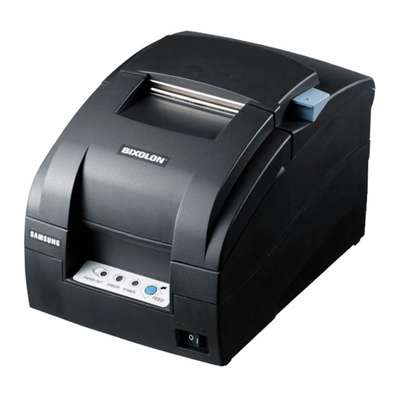
- Page 1 Operator’s manual POS impact dot matrix printer SRP-275 ELECTRO - MECHANICS printed in korea 2004. 09 ELECTRO - MECHANICS...
-
Page 2: Safety Precautions
Safety Precautions In using the present appliance, please keep the following safety regulations in order to prevent any hazard or material damage. WARNING Violating following instructions can cause serious injury or death. Do not plug several products in one multi-outlet. You must use only the supplied adaptor. - Page 3 A damaged cable can cause a fire. maintenance instructions. SAMSUNG ELECTRO-MECHANICS shall not be liable against any damages or problems arising from the use of any options or ant consumable products other than those designated as Original Samsung products or PROHIBITED PROHIBITED Samsung Approved products by SAMSUNG ELECTRO-MECHANICS.
-
Page 4: Table Of Contents
5.3.2 Undefined commands 5.3.3 settings outside the defined range Chapter 3 DIP Switch 5.4 Commands for SRP-275 Series 5.4.1 Commands list for Epson mode (TM-U220) 3.1. Setting the DIP Switches 5.4.2 Commands description for Epson mode (TM-U220) 3.1.1 DIP Switch Setting for Epson(ESC/POS) mode 5.4.3 Commands list for STAR mode (SP500) - Page 5 Introduction CHAPTER The SRP-275 is a high-quality impact dot matrix POS printer. This one-station printer has the following features. Compact design and light-weight. High-speed printing using logic-seeking(5.3LPS). Easy to use : clamshell mechanism. High reliability and long life due to the use of stepping motors for head carriage return and paper feeding.
-
Page 6: Unpacking
4) Plug the AC adaptor cable into the printer’s power connector. 5) Plug the power cord into the outlet, and turn on the power. AC adaptor Power cord SRP-275 A , C Ribbon Cassette Paper roll Quick reference sheet Operator’s manual... -
Page 7: Installing Ribbon Cassette
CHAPTER 1 Setting up the printer 1.4 Installing ribbon cassette 1.5 Installing paper roll 1) Before inserting the ribbon cassette, turn the knob clockwise to prevent twisting the ribbon. Notice the caution label and do not touch the auto cutter blade when you open rear cover. 1) To prevent data loss, make sure that the printer is not receiving data. -
Page 8: Changing The Frame Control Paper Position
CHAPTER 1 Setting up the printer 1.7 Changing the frame control paper position 1.8 Installing wall mount (Option) 1) Open the rear cover. 2) Remove the frame control paper by loosing the two screws(3 x 6).(76 mm default) 1) Turn the Set over and attach the Bracket hanger to the Frame base then tighten four screws. -
Page 9: Using The Operation Panel
CHAPTER 1 Setting up the printer 1.9 Using the operation panel 1.9 Self test Most of the functions of this printer are governed by software, but you can monitor the printer s status by The self test let you know if your printer is operating properly. It checks the printing quality, ROM version, looking at the lights on the operation panel and for some procedures you will use the buttons. -
Page 10: Error Led Blinking Pattern
Note Note CHAPTER TROUBLESHOOTING 2.1 ERROR LED blinking pattern 2.2 The printer does not start printing 2.3 The printer stops printing 2.4 You want to check the operation of the printer by itself 2.5 Printing is poor 2.6 You want to check a software program 1-11... -
Page 11: The Printer Does Not Start Printing
CHAPTER 2 Troubleshooting This chapter gives solutions to some printer problems you may have. 2.1 ERROR LED blinking pattern The printer stops all printer operations for the selected paper section, goes off line, and the ERROR LED Errors that are impossible to recover blinks when an error is detected. -
Page 12: The Printer Stops Printing
CHAPTER 2 Troubleshooting 2.3 The printer stops printing 2.6 You want to check a software program If the ERROR LED is on (but not blinking), the printer is off line. Check to see that the covers are closed Hexadecimal dump and check the paper state. - Page 13 Note Note Note Note CHAPTER SWITCH SETTINGS 3.1 Setting the DIP Switches 3.1.1 DIP Switch Setting for Epson(ESC/POS) mode 3.1.2 DIP Switch setting for Citizen(iDP 3550) mode 3.1.3 DIP Switch setting for Star(SP500) mode 3.2 Setting the Memory Switches 3.2.1 Memory Switch setting for Epson(ESC/POS) mode 3.2.2 Memory Switch setting for Star(SP500) mode...
-
Page 14: Chapter 3 . Dip Switch
CHAPTER 3 Switch settings Although the factory settings are best for almost all users, if you have special requirements, you can change the DIP Switch. 3.1 Setting the DIP Switches Your printer has two sets of DIP Switches. The functions of the switches are shown in the following table. 3.1.1 DIP Switch setting for Epson (ESC/POS) mode DIP Switch 1 (*1) Emulation Selection (DSW 1-1and 1-2) -
Page 15: Dip Switch Setting For Star(Sp500) Mode
CHAPTER 3 Switch settings DIP Switch 2 (RS232C serial interface model) 3.1.3 DIP Switch setting for Star(SP500) mode Switch Function Default DIP Switch 1 Word length 8 bits 7 bits Switch Function Default Parity check Disable Enable Parity selection EVEN Emulation selection(*1) Refer to the following table Handshaking... -
Page 16: Setting The Memory Switches
Page 26 (WPC1257 : Baltic) the settings are maintained. Page 27 (Farsi) When you replace a SRP-270 with a SRP-275, you should adjust the MSW8-5 to OFF. Page 28 (WPC1251 : Russian) (*2) Page 29 (PC737 : Greek) (*2) Page 30 (PC775 : Baltic) (*2) -
Page 17: Switch Settings
- Transmission speed printer is changed every time the rear cover is open or closed. When you replace a SRP- - Parity 270 with a SRP-275, you should adjust the MSW 8-5 to Off. - Handshaking MSW 8-8 : - Data length When Off is selected, a bit of the "automatic recoverable error"... -
Page 18: Memory Switch Setting For Star(Sp500) Mode
CHAPTER 3 Switch settings Procedure of Memory Switch setting 3.2.2 Memory Switch setting for Star (SP500) mode Settings Memory Switches are from MSW 0 to 8 MSW 8. They are stored in non-volatile memory (flash memory). To change the settings, send the following commands from the host. [Name] Set Memory Switch [Code] ASCII... - Page 19 CHAPTER 3 Switch settings Default Settings Function The default settings for Memory Switch 0 to Memory Switch 8 are shown below. Memory Switch 0 Settings vary for single byte character countries (standard specifications (SBCS)) and for double-byte Function character countries (Chinese character specifications (DBCS)). Reserved Red and black Standard specifications (SBCS)
-
Page 20
CHAPTER 3 Switch settings Memory Switch 1 Function Reserved (*3) Red and Black (inverted black and white) Commands Zero style Normal Slash zero MSW0-3 MSW0-2
4 / 5 Command Functions International Characters(*1) Refer to the following table White/black inverted printing (1 Pass) -
Page 21
CHAPTER 3 Switch settings Memory Switch 2 Memory Switch 3 Function Function Reserved How to recover to print ready after Character Table(*2) Refer to the following table Press FEED Auto-recovery Inserting paper Reserved
Command Functions(*1) Refer to the following table Printing region width(*1) Refer to the following table Paper width selection(*1) -
Page 22: Changing The Dip Switch Setting
CHAPTER 3 Switch settings 3.3 Changing the DIP Switch setting If you need to change settings, follow the steps below to make your changes. Memory Switch 4 Function Turn off the printer before removing the DIP Switch cover to prevent an electric short, which can damage the printer. -
Page 23: Page 0 (Pc437 : Usa, Standard Europe (International Character Set : Usa))
Note Note CHAPTER CODE TABLE 4.1 Page 0 (PC437 : USA, Standard Europe (International Character Set : USA)) 4.2 Page 1 (Katakana) 4.3 Page 2 (PC850 : Multilingual) 4.4 Page 3 (PC860 : Portuguese) 4.5 Page 4 (PC863 : Canadian-French) 4.6 Page 5 (PC865 : Nordic) 4.7 Page 16 (WPC1252 : Latin1) 4.8 Page 17 (PC866 : Russian) -
Page 24: Katakana)
CHAPTER 4 Code table The following pages show the character code tables. To fine the character corresponding to a hexadecimal number, count across the top of the table for the left digit and count down the left column of the table right digit. For example, 4A=J 4.1 Page 0 (PC 437 : USA, Standard Europe ( 4.2 Page 1 (Katakana) International Character Set : USA) -
Page 25: Pc850 : Multilingual)
CHAPTER 4 Code table 4.3 Page 2 (PC850 : Multilingual) 4.4 Page 3 (PC860 : Portuguese) -
Page 26: Pc865 : Nordic)
CHAPTER 4 Code table 4.5 Page 4 (PC863 : Canadian-French) 4.6 Page 5 (PC865 : Nordic) -
Page 27: Wpc1252 : Latin1)
CHAPTER 4 Code table 4.7 Page 16 (WPC1252 : Latin1) 4.8 Page 17 (PC866 : Russian) -
Page 28: Pc852 : Doslatin2)
CHAPTER 4 Code table 4.9 Page 18 (PC852 : DosLatin2) 4.10 Page 19 (PC858 : Euro) 4-10 4-11 4-11... -
Page 29: Pc862 : Israel)
CHAPTER 4 Code table 4.11 Page 21 (PC862 : Israel) 4.12 Page 22 (PC864 : Arabic) 4-12 4-13 4-13... -
Page 30: Thai Character Code 42)
CHAPTER 4 Code table Thai character code 42 WPC1253 : Greek 4.13 Page 23 ( 4.14 Page 24 ( 4-14 4-15... -
Page 31: Wpc1254 : Turkish)
CHAPTER 4 Code table WPC1254 : Turkish Baltic 4.15 Page 25 ( 4.16 Page 26 (WPC1257 : 4-16 4-17... -
Page 32: Farsi)
CHAPTER 4 Code table Farsi WPC1251 : Russian 4.17 Page 27 ( 4.18 Page 28 ( 4-18 4-19... -
Page 33: Pc737 : Greek)
CHAPTER 4 Code table PC737 : Greek PC775 : Baltic 4.19 Page 29 ( 4.20 Page 30 ( 4-20 4-21... -
Page 34: International Character Code Table
CHAPTER 4 Code table International character code table 4.21 4-22... -
Page 35: Explanation Of Terms
5.3 Explanation Processing 5.3.1 Undefined codes 5.3.2 Undefined commands 5.3.3 settings outside the defined range 5.4 Commands for SRP-275 Series 5.4.1 Commands list for Epson mode (TM-U220) 5.4.2 Commands description for Epson mode (TM-U220) 5.4.3 Commands list for STAR mode (SP500) 5-74 5.4.4 Commands description for... - Page 36 CHAPTER 5 CONTROL COMMANDS LIST 5.1 Command notation 5.3 Exception processing X X X X 5.3.1 Undefined codes This term refers to the codes ranging from 00H to 1FH in the character code table. If a code in this [Name] The name of the command.
-
Page 37: Commands For Srp-275 Series
CHAPTER 5 CONTROL COMMANDS LIST 5.4 Commands for SRP-275 Series 5.4.1 Commands list for EPSON Mode(TM-U220) Command Description Command Description Horizontal tab FS p Print NV bit image 1C 70 Print and line feed FS q Define NV bit image... -
Page 38: Commands Description For Epson Mode (Tm-U220)
CHAPTER 5 CONTROL COMMANDS LIST 5.4.2 Commands description for Epson mode (TM-U220) [Name] Horizontal tab [Name] Print and carriage return [Format] ASCII [Format] ASCII Decimal Decimal [Range] None [Range] None [Default] None [Default] None [Description] Moves the printing position to the next horizontal tab. [Description] [Notes] This command is ignored unless the next horizontal tab position... -
Page 39: Dle Eot
CHAPTER 5 CONTROL COMMANDS LIST Printer status (n = 1) is as follows: DLE EOT Binary Decimal Status [Name] Real-time status transmission Not used. Fixed to Off [Format] ASCII Not used. Fixed to On Drawer kick-out connector pin 3 is LOW Drawer kick-out connector pin 3 is HIGH Decimal Online... -
Page 40: Dle Enq
CHAPTER 5 CONTROL COMMANDS LIST Error status (n = 3) is as follows: DLE ENQ Binary Decimal Status [Name] Real-time request to printer Not used. Fixed to Off [Format] ASCII Not used. Fixed to On No mechanical error Mechanical error occurred Decimal No auto cutter error Auto cutter error occurred... -
Page 41: Dle Dc4(Fn = 1)
CHAPTER 5 CONTROL COMMANDS LIST DLE DC4 (fn = 1) ESC SP [Name] Generate pulse at real-time [Name] Set right-side character spacing [Format] ASCII [Format] ASCII Decimal Decimal 0 ≤ n ≤ 255 [Range] n = 1 [Range] m = 0, 1 [Default] n = 0 1 ≤... -
Page 42: Esc
CHAPTER 5 CONTROL COMMANDS LIST [Notes] Functions for each bit can also be executed by the following commands: ESC & - Bit 0 (character font): ESC M [Name] Define user-defined characters - Bit 3 (Emphasized mode): ESC E - Bit 7 (underline mode): ESC — [Format] ASCII &... -
Page 43: Esc
CHAPTER 5 CONTROL COMMANDS LIST The modes selectable by m are as follows: ESC * - "Vertical" is in the direction of paper feeding and "horizontal" is perpendicular [Name] Select bit-image mode (at right angles) to the direction of paper feeding. [Format] ASCII d1 ... -
Page 44: Esc
CHAPTER 5 CONTROL COMMANDS LIST ESC 2 ESC < [Name] Select default line spacing [Name] Return home [Format] ASCII [Format] ASCII < Decimal Decimal [Range] None [Range] None [Default] None [Default] None [Description] Sets the line spacing to the "default line spacing." [Description] Moves the print head to the standby position. -
Page 45: Cancel User-Defined Characters
CHAPTER 5 CONTROL COMMANDS LIST ESC ? ESC D [Name] Cancel user-defined characters [Name] Set horizontal tab positions [Format] ASCII [Format] ASCII n1 ... nk NUL n1 ... nk 00 Decimal Decimal n1 ... nk 0 32 ≤ n ≤ 126 0 ≤... - Page 46 CHAPTER 5 CONTROL COMMANDS LIST ESC E ESC J [Name] Turn emphasized mode on/off [Name] Print and feed paper [Format] ASCII [Format] ASCII Decimal Decimal 0 ≤ n ≤ 255 [Range] 0 ≤ n ≤ 255 [Range] [Default] None [Default] n = 0 [Description] Prints the data in the print buffer and feeds the paper n.
- Page 47 CHAPTER 5 CONTROL COMMANDS LIST ESC M ESC U [Name] Select character font [Name] Turn unidirectional printing mode on / off [Format] ASCII [Format] ASCII Decimal Decimal 0 ≤ n ≤ 255 [Range] [Range] n = 0, 1, 48, 49 [Default] n = 0 [Default]...
- Page 48 CHAPTER 5 CONTROL COMMANDS LIST ESC c 3 ESC c 4 [Name] Select paper sensor(s) to output paper end signals [Name] Select paper sensor(s) to stop printing [Format] ASCII [Format] ASCII Decimal Decimal 0 ≤ n ≤ 255 0 ≤ n ≤ 255 [Range] [Range] [Default]...
- Page 49 CHAPTER 5 CONTROL COMMANDS LIST ESC c 5 ESC e [Name] Enable/disable panel buttons [Name] Print and reverse feed n lines [Format] ASCII [Format] ASCII Decimal Decimal 0 ≤ n ≤ 255 0 ≤ n ≤ 1 [Range] [Range] [Default] n = 0 [Default] None...
- Page 50 - m = (256 x nH) + nL Drawer kick-out connector pin 2 [Notes] The SRP-275 Printer maintains a 2M bit (256KB) section of flash Drawer kick-out connector pin 5 memory to save NV bit image. - The pulse for ON time is (t1 x 2 msec) and for OFF time is (t2 x 2 msec).
- Page 51 CHAPTER 5 CONTROL COMMANDS LIST ESC r ESC t [Name] Select print color [Name] Select paper sensor(s) to output paper-end signals [Format] ASCII [Format] ASCII Decimal Decimal [Range] n = 0, 1, 48, 49 [Range] n = 0, 1, 2, 3, 4, 5, 16, 17, 18, 19, 21, 22, 23, 24, 25, 26, 27, 28, 29, 30, 255 [Default] n = 0 [Default]...
- Page 52 CHAPTER 5 CONTROL COMMANDS LIST ESC u ESC v [Name] Transmit peripheral device status. [Name] Transmit peripheral device status. [Format] ASCII [Format] ASCII Decimal Decimal [Range] n = 0, 48 [Description] Transmit the status of paper sensor(s) as 1 byte of data. [Default] Transmit the peripheral device status of 1 byte.
- Page 53 CHAPTER 5 CONTROL COMMANDS LIST FS p [Name] Turn upside-down printing mode on/off. [Name] Print NV bit image [Format] ASCII [Format] ASCII Decimal Decimal 1 ≤ n ≤ 255 1 ≤ n ≤ 255 [Range] [Range] [Default] n = 0 m = 0, 1, 48, 49 [Description] Turn upside-down printing mode on or off.
- Page 54 CHAPTER 5 CONTROL COMMANDS LIST The modes selectable by m are as follows : - k indicates the number of the definition data. k is a parameter for an "Vertical" is in the direction of paper feeding and "horizontal" is perpendicular explanation;...
- Page 55 CHAPTER 5 CONTROL COMMANDS LIST GS ( A GS ( C [Name] Execute test print [Name] Edit NV user memory [Format] ASCII [Format] ASCII GS pL pH m [c1, c2] [d1...dk] 1D 28 43 pL pH m [c1, c2] [d1...dk] Decimal 29 Decimal 29 40 67 pL pH m...
- Page 56 CHAPTER 5 CONTROL COMMANDS LIST NV user memory data remains valid until the host sends a deletion or [Notes for ESC/POS Handshaking Protocol] storage function command. Use ESC/POS Handshaking Protocol below for Functions 2 and 5: identifier. Data is written to the non-volatile memory by Function 1, 2, or 3. Step Host process Printer process...
-
Page 57
CHAPTER 5 CONTROL COMMANDS LIST [Description] Stores data ( d1... dk) in the record specified by parameters c1 and c2 GS ( C pL pH m fn b c1 c2
(the key code ID numbers). [Format] ASCII c1 c2 - When the specified record already exists, the data is overwritten. -
Page 58
CHAPTER 5 CONTROL COMMANDS LIST [Notes] - When the specified record exists, the printer sends the "Header to NUL" GS ( C pL pH m fn b
data shown below: [Format] ASCII Send data Decimal Data quantity Header 1 byte Identifier 1 byte... -
Page 59
CHAPTER 5 CONTROL COMMANDS LIST GS ( C pL pH m fn b
GS ( C pL pH m fn b [Format] ASCII [Format] ASCII Decimal Decimal [Range] (pL + pHx 256) = 3 (pL = 3, pH = 0) [Range] (pL + pH x 256) = 3 (pL = 3, pH = 0) m = 0... - Page 60 CHAPTER 5 CONTROL COMMANDS LIST - See [Notes for transmission process] for description of transmission GS ( D process. [Name] Enable/disable real-time command - See [Notes for ESC/POS Handshaking Protocol] for description of [Format] ASCII [a1 b1]...[ak bk] ESC/POS Handshaking Protocol. [a1 b1]...[ak bk] Decimal 29 [a1 b1]...[ak bk]...
- Page 61 CHAPTER 5 CONTROL COMMANDS LIST - Functions 4, 6, 12, the functions used to transmit the current settings to the GS ( E host, can be used at any time, without changing into the user setting mode. [Name] User setup commands - Data is written to the non-volatile memory by Functions 3, 5 and 11.
-
Page 62
CHAPTER 5 CONTROL COMMANDS LIST GS ( E pL pH fn d1 d2
GS ( E pL pH fn d1 d2 d3 [Format] ASCII [Format] ASCII Decimal 29 Decimal 29 [Range] (pL + pH x 256) = 3 (pL = 3, pH = 0) [Range] (pL + pH x 256) = 4 (pL = 4, pH = 0) fn = 1... -
Page 63
CHAPTER 5 CONTROL COMMANDS LIST GS ( E pL pH fn [a1 b18...b11]...[ak nk8 nk1]
GS ( E pL pH fn a [Format] ASCI [a1 b18...b11 ]...[ak nk8 nk1] [Format] ASCII [a1 b18...b11]...[ak nk8 nk1] Decimal 29 [a1 b18...b11]...[ak nk8 nk1] Decimal 29 [Range]... -
Page 64
CHAPTER 5 CONTROL COMMANDS LIST GS ( E pL pH fn [a1 n1L n1H]...[ak nkL nkH]
GS ( E pL pH fn a [Format] ASCII [a1n1L n1H] ... [ak nkL nkH] [Format] ASCII [a1 n1L n1H] ... [ak nkL nkH] Decimal 29 [a1 n1L n1H] ... -
Page 65
CHAPTER 5 CONTROL COMMANDS LIST Bit length ( a = 4) is specified by d as follows: GS ( E pL pH fn a d1...dk
[Format] ASCII d1...dk Function Select 7 bits length d1...dk Select 8 bits length Decimal 29 d1...dk [Notes]... -
Page 66
CHAPTER 5 CONTROL COMMANDS LIST GS ( E pL pH fn a
GS I [Format] ASCII [Name] Transmit printer ID [Format] ASCII Decimal 29 [Range] (pL + pH x 256) = 2 (pL = 2, pH = 0) Decimal 29 fn = 12 1 ≤... - Page 67 CHAPTER 5 CONTROL COMMANDS LIST [Notes for printer ID] (*1) The identifier is transmitted as the transmitted parameter n of this command. Each printer ID is composed of 1 byte of data (when 1 ≤ n ≤ 3, 49 ≤ n ≤ 51). Example: When type information is specified (n = 33), the identifier is Printer model ID differs, depending on the printer model (when n = 1, 49).
- Page 68 When n = 0, the printer feeds the paper to the cutting position and cuts it. Printer model (n = 67) If an auto cutter is not provided, the printer only feeds the paper for specified Printer model: SRP-275 amount. Type information (n = 33) Vertical motion unit is used for calculating a paper feed amount.
- Page 69 CHAPTER 5 CONTROL COMMANDS LIST Therefore you cannot get the printer status change through ASB status GS a when block data [header - NUL] is transmitted. [Name] Enable/disable Automatic Status Back (ASB) Any basic ASB status represents the enabled status whenever the status [Format] ASCII changes.
- Page 70 CHAPTER 5 CONTROL COMMANDS LIST [Note] Only if ESC 4 is selected or paper stop printing sensor is not selected. Third byte (paper sensor information) Basic ASB status is 4-byte configuration [first byte - fourth byte]. Off/On Decimal Function The status to be transmitted are as follows: Paper near end sensor: paper adequate.
- Page 71 CHAPTER 5 CONTROL COMMANDS LIST When you use this command, obey the following rules. GS r - After the host PC transmits the function data, the printer will send [Name] Transmit status response data or status data back to the PC. Do not transmit more data [Format] ASCII from the PC until the response data or status data are received from the...
-
Page 72: Commands List For Star Mode (Sp500)
CHAPTER 5 CONTROL COMMANDS LIST 5.4.3 Commands list for STAR mode (SP500) Command Description Command Description ESC GS t Specify code page 1B 1D 74 Move print position to horizontal tab position ESC R Specify international character set 1B 52 ESC D Set/cancel horizontal tab position 1B 44... -
Page 73: Commands List For Citizen Mode (Idp3550/3551)
5.4.5 Commands list for CITIZEN mode (iDP3550/3551) Command Description FF n n-line paper feed (CBM1 mode) 0C n Form feed (CBM2 mode) SO (Note) Specifying the double width character (CBM1 mode) SI (Note) Canceling the double width character Print and paper feed Printing DC1 (Note) Initializing the printer (CBM1 mode) - Page 74 CHAPTER 5 CONTROL COMMANDS LIST 5.4.6 Commands description CITIZEN mode (iDP3550/3551) FF n (CBM1 Mode) Function Command Code 8-bit data selected 7-bit data selected [Name] n-line paper feed Specifying the double width Specifying the shift-out side [Format] ASCII character character Canceling the double width Specifying the shift-in side character...
- Page 75 CHAPTER 5 CONTROL COMMANDS LIST (CBM2 Mode) [Name] Specifying the double width character/shift-out side characters [Name] Printing and paper feed [Format] ASCII [Format] ASCII [Description] The data following this command is printed doubled in the horizontal direction. [Description] If the print buffer contains the data, this command will feed the line after Double width characters remain valid until the double width character cancel printing.
- Page 76 CHAPTER 5 CONTROL COMMANDS LIST (CBM2 Mode) (CBM1 Mode) [Name] Setting the select mode [Name] Specifying the red print [Format] ASCII [Format] ASCII [Description] This command sets the printer in the selecting status. [Description] This command specifies red-color characters. All the characters in one line are printed in red by prefixing the print data with this command and sending it to the printer.
- Page 77 CHAPTER 5 CONTROL COMMANDS LIST ESC * n1 n2 ESC - n [Name] Specifying the bit image mode [Name] Specifying/Canceling the underline [Format] ASCII [Format] ASCII 1 ≤ n1 + 256 x n2 ≤ 360 (for DP654 mechanism) [Range] [Default] n = 0 1 ≤...
- Page 78 CHAPTER 5 CONTROL COMMANDS LIST ESC 3 ESC O [Name] Canceling the perforation skip [Name] Specifying the standard line feed width [Format] ASCII [Format] ASCII [Description] This command cancels perforation skipping operation. [Description] This command sets the line feed width as follows. Character type : 1/6 inch Graphic type : 2/9 inch ESC C n...
- Page 79 CHAPTER 5 CONTROL COMMANDS LIST ESC t n ESC BEL n1 n2 [Name] Selecting the character code table [Name] Setting the external device drive pulse width [Format] ASCll [Format] ASCII BEL n1 n2 n1 n2 0 ≤ n ≤ 30 1 ≤...
- Page 80 CHAPTER 5 CONTROL COMMANDS LIST ESC P <0> [Name] Driving command B for drawer-1 [Name] Partial cut [Format] ASCII [Format] ASCII <0> [Description] This command drives the drawer connector No. 2 pin under the condition set [Description] This command partially cuts the paper with the ESC BEL n1 n2 command.
- Page 81 CHAPTER 5 CONTROL COMMANDS LIST ESC & <0> n1 n2 [m0 m1 m5 m6 m7 m8 m9] n2 — n1 +1 ESC % n [Name] Defining the download character set [Name] Specifying/Canceling the download character set [Format] ASCII & <0> n2 [m0 m8 m9] n2-n1+1 [Format] ASCII...
- Page 82 CHAPTER 5 CONTROL COMMANDS LIST ESC DC3 n ESC DC2 n1 n2 [Name] Printing the message [Name] Deleting the download character, message, bit image [Format] ASCII [Format] ASCII 1 ≤ n ≤ 10 0 ≤ n1 ≤ 3 [Range] [Range] 0 ≤...
- Page 83 CHAPTER 5 CONTROL COMMANDS LIST GS * n1 n2 [d] n1xn2x8 GS / m [Name] Defining the download bit image [Name] Printing the download bit image [Format] ASCII [d] n1xn2x8 [Format] ASCII m [d] n1xn2x8 1 ≤ n1 ≤ 45 0 ≤...
- Page 84 CHAPTER 5 CONTROL COMMANDS LIST 5.4.4 Command description for STAR mode (SP500) ESC GS t n ESC R n [Name] Select code page [Name] Specify international character set [Format] ASCII [Format] ASCII Decimal Decimal ≤ n ≤ 30 0 ≤ n ≤ 10 [Range] [Range] [Default]...
- Page 85 CHAPTER 5 CONTROL COMMANDS LIST ESC M ESC SP n [Name] Specify 7 x 9 font (half dots) (default) [Name] Specify character space [Format] ASCII [Format] ASCII Decimal Decimal 0 ≤ n ≤ 15 [Range] [Range] ------ [Default] n = 1 [Default] ------ [Description]...
- Page 86 CHAPTER 5 CONTROL COMMANDS LIST ESC W n ESC E [Name] Specify/cancel expanded double-wide printing [Name] Select emphasized printing [Format] ASCII [Format] ASCII Decimal Decimal [Range] ------ [Range] n = 0, 1, 48, 49 [Default] Emphasized printing cancelled [Default] n = 0 (Double wide printing cancelled) [Description] Specifies emphasized printing for subsequent data.
- Page 87 CHAPTER 5 CONTROL COMMANDS LIST ESC - n ESC 4 [Name] Specify/cancel underline mode Name] Specify white/black inversion and red color printing [Format] ASCII [Format] ASCII Decimal Decimal [Range] ------ [Range] n = 0, 1, 48, 49 [Default] White/black inversion cancelled/black color printing specified [Default] n = 0 (Underline cancelled) [Description]...
- Page 88 CHAPTER 5 CONTROL COMMANDS LIST ESC RS i n [Name] Select upside-down printing [Name] Specify/cancel character rotate mode [Format] ASCII [Format] ASCI Decimal Decimal 0 ≤ n ≤ 2 [Range] ------ [Range] 48 ≤ n ≤ 50 ("0" ≤ n ≤ "2") [Default] Upside-down printing cancelled [Description]...
- Page 89 CHAPTER 5 CONTROL COMMANDS LIST ESC a n Name] Line feed [Name] Feed paper n lines [Format] ASCII [Format] ASCII Decimal Decimal 1 ≤ n ≤ 127 [Range] ------ [Range] [Default] Set line feed to 1/6 inch [Default] ------ [Description] After printing data in the line buffer, paper is fed according to the currently [Description] After printing data in the line buffer, paper is fed according to the currently...
- Page 90 CHAPTER 5 CONTROL COMMANDS LIST ESC z 0 ESC 2 [Name] Set line feed to 1/12 inch [Name] Set ESC A line feed pitch [Format] ASCII "0" [Format] ASCII Decimal Decimal [Range] ------ [Range] ------ [Default] 1/6 inch [Default] ------ [Description] Sets subsequent line feeds to 1/12 inch.
- Page 91 CHAPTER 5 CONTROL COMMANDS LIST ESC J n [Name] Execute n/72 inch paper feed one time [Name] Form feed [Format] ASCII [Format] ASCII Decimal Decimal 1 ≤ n ≤ 255 [Range] [Range] ------ [Default] ------ [Default] ------ [Description] After printing data in the line buffer, paper is fed n/72 of an inch in the paper [Description] This command performs the following operations after the printer prints the feed direction.
- Page 92 CHAPTER 5 CONTROL COMMANDS LIST ESC C n [Name] Set page length to n lines [Name] Feed paper to vertical table position [Format] ASCII [Format] ASCII Decimal Decimal 1 ≤ n ≤ 255 [Range] [Range] ------ [Default] 1/6 inch x 42 [Default] ------ [Description]...
- Page 93 CHAPTER 5 CONTROL COMMANDS LIST ESC N n ESC O [Name] Set bottom margin to n lines [Name] Cancel bottom margin [Format] ASCII [Format] ASCII Decimal Decimal 0 ≤ n ≤ 255 [Range] [Range] ------ [Default] n = 0 [Default] (Not set) [Description] This command sets the bottom margin position to...
- Page 94 CHAPTER 5 CONTROL COMMANDS LIST ESC l n ESC Q n Name] Set left margin [Name] Set right margin [Format] ASCII [Format] ASCII Decimal Decimal 0 ≤ n ≤ (Right margin -2) ≤ 255 2 ≤ n ≤ Maximum printable digits ≤ 255 [Range] [Range] [Default]...
- Page 95 CHAPTER 5 CONTROL COMMANDS LIST ESC D n1 n2 nk NUL [Name] Move horizontal tab [Name] Set horizontal tab [Format] ASCII [Format] ASCII Decimal Decimal 1 ≤ n ≤ Maximum printable digits ≤ 255 [Range] ------ [Range] 0 ≤ k ≤ 16 [Default] ------ [Default]...
- Page 96 CHAPTER 5 CONTROL COMMANDS LIST ESC GS a n ESC GS A n1 n2 [Name] Specify position alignment [Name] Specify absolute position [Format] ASCII [Format] ASCII Decimal Decimal 0 ≤ n ≤ 2 0 ≤ n1 ≤ 255 [Range] [Range] 48 ≤...
- Page 97 CHAPTER 5 CONTROL COMMANDS LIST ESC & NUL n1 n2 [m d1 d2 d3 d4 d5 (d6 d7)] ESC % n n2-n1+1 [Name] Register/cancel download characters [Name] Set/cancel download characters [Format] ASCII & n2[m d1 d2 d3 d4 d5 (d6 d7)]n2-n1+1 [Format] ASCII n2[m d1 d2 d3 d4 d5 (d6 d7)]n2-n1+1...
- Page 98 CHAPTER 5 CONTROL COMMANDS LIST ESC K n NUL d1 d2 dn ESC L n1 n2 d1 d2 dk [Name] Standard density bit image [Name] Double density bit image [Format] ASCII [Format] ASCII Decimal 27 Decimal 27 1 ≤ n ≤ Total dot count(200 dots) 1 ≤...
- Page 99 CHAPTER 5 CONTROL COMMANDS LIST ESC d n ESC BEL n1 n2 [Name] Paper cut instruction [Name] Set external drive device 1 pulse width [Format] ASCII [Format] ASCII ESC BEL Decimal 27 Decimal 27 0 ≤ n ≤ 3 1 ≤ n1 ≤ 127 [Range] [Range] 48 ≤...
- Page 100 CHAPTER 5 CONTROL COMMANDS LIST [Name] External device 1 drive instruction [Name] External device 2 drive instruction (real time) [Format] ASCII [Format] ASCII Decimal Decimal [Range] ------ [Range] ------ [Description] Executes the external device drive conditions set according to the [Default] ------ ESC BEL (external device drive pulse width setting command).
- Page 101 CHAPTER 5 CONTROL COMMANDS LIST [Name] Inquire ENQ status [Name] Inquire EOT status [Format] ASCII [Format] ASCII Decimal Decimal [Range] ------ [Range] ------ [Default] ------ [Default] ------ [Description] This command is effective only when using an interface capable of [Description] This command is effective only when using an interface capable of bi-directional data communications.
- Page 102 CHAPTER 5 CONTROL COMMANDS LIST Auto status ESC ACK SOH Header 1 (First byte) [Name] Inquire status Status [Format] ASCII Contents "0" "1" Fixed at "0" Reserved (Fixed at "0") Decimal Printer status Byte count checked [Range] ------ Fixed at "0" Printer status Byte count [Default] ------...
- Page 103 CHAPTER 5 CONTROL COMMANDS LIST Printer status 2 Error information (Fourth byte) Printer status 5 Sensor information (Seventh byte) Status Status Contents Contents "0" "1" "0" "1" Fixed at "0" Fixed at "0" Stopped by high head Not used (Fixed at "0") Not stopped Stopped temperature...
- Page 104 CHAPTER 5 CONTROL COMMANDS LIST ESC RS a n [Name] Sets auto status transmission conditions [Name] Update ETB status (check after printing) [Format] ASCII [Format] ASCII Decimal Decimal [Description] This command is effective only when using an interface capable of 0 ≤...
- Page 105 CHAPTER 5 CONTROL COMMANDS LIST ESC RS E n [Name] Clear the ETB counter and ETB status 30 69 n [Name] Printer deselect [Format] ASCII [Format] ASCII Decimal Decimal [Range] n = 0 [Range] ------ n = 48 ("0") [Default] Select printer [Default] ------...
- Page 106 CHAPTER 5 CONTROL COMMANDS LIST ESC @ ESC GS # m N n1 n2 n3 n4 LF NUL [Name] Command initialization [Name] Set memory switch [Format] ASCII [Format] ASCII LF NUL Decimal Decimal [Range] ------ [Range] m = 87, 84, 44, 43, 45, 64 ( m = "W", "T", ",", "+", "-", "@" ) 48 ≤N ≤...
- Page 107 CHAPTER 5 CONTROL COMMANDS LIST ESC ? LF NUL [Name] Reset printer and execute self print [Format] ASCII Decimal [Range] ------ [Default] ------ [Description] Hardware resets the printer and executes on self print. After sending this command, the next data should not be sent until the printer is online (in a state wherein it can receive data).
-
Page 108: Printing Specification
CHAPTER REFERENCE INFORMATION 6.1 Printing specification 6.2 Paper specification 6.3 Ribbon cassette specification 6.4 Electrical characteristics 6.5 Reliability 6.6 Environmental 6.7 Dimensions & Weight 6.8 Optional features... - Page 109 CHAPTER 6 Reference information 6.1 Printing specification 6.4 Electrical characteristics Item Description Item Description Supply voltage 24V DC ± 10% Printing method Serial impact dot matrix method Current consumption Mean : Approximately 0.5A Head wire 9pin serial type Operating (at 24V, except for drawer Peak : Approximately 1.5A Dot pitch 0.352 mm (1/72")
- Page 110 CHAPTER 6 Reference information 6.7 Dimensions & weight Dimensions Item Dimensions (mm) Weight Approx. Wt. : 2.6 kg Shipping Wt. : 3.4 kg 6.8 Optional features The optional features either replace a standard feature or enhance the operation of the printer. All optional features are installed at the factory and must be selected when the printer is ordered.