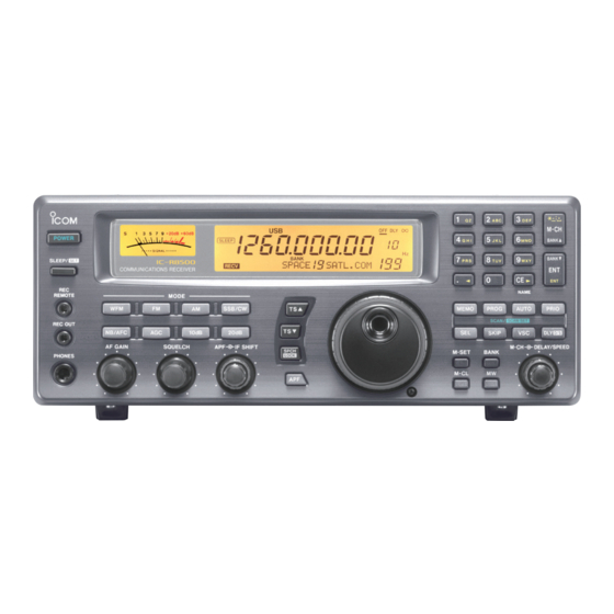
Icom IC-R8500 Instruction Manual
Communications receiver
Hide thumbs
Also See for IC-R8500:
- Service manual addendum (286 pages) ,
- Service manual (101 pages) ,
- Instruction manual (48 pages)

Related Manuals for Icom IC-R8500


Summary of Contents for Icom IC-R8500
- Page 1 INSTRUCTION MANUAL COMMUNICATIONS RECEIVER iC-r8500...
-
Page 2: Important
RWARNING! NEVER expose the connect the receiver to an IC-R8500 or AC adapter to rain, snow or any liquids. AC outlet directly. This may pose a fire hazard or result in an electric shock. Always use an optional AC DO NOT use or place the receiver in areas with adapter or connect to a 13.8 V DC power source. -
Page 3: Table Of Contents
TABLE OF CONTENTS 8 SET MODE ............30 IMPORTANT ............i EXPLICIT DEFINITIONS ......... i ■ General ..............30 PRECAUTIONS ............i ■ Quick set mode items ..........31 UNPACKING ............i ■ Initial set mode items ..........31 TABLE OF CONTENTS ........... ii 9 CONNECTOR INFORMATION .... -
Page 4: Panel Description
PANEL DESCRIPTION ■ Front panel 1 3 5 7 9 + 20dB + 60dB POWER SLEEP LOCK SIGNAL AGC-F APF-N BANK SEL-CH iC-r8500 ICOM IC-R SLEEP/ RECV 10-ATT-20 COMMUNICATION RECEIVER REMOTE MODE SSB/CW REC OUT NB/AFC 10dB 20dB AF GAIN... - Page 5 PANEL DESCRIPTION . ; , M-CH BANK SKIP-CH BANK R8500 NAME MEMO PROG AUTO PRIO SCAN/ SCAN SET SKIP M-CH DELAY/SPEED M-SET BANK M-CL !5 !6 • Automatic announcement at signal detection during Center frequency Center frequency scan is available. Refer to the “REC SPCH” item on is shifted down.
- Page 6 PANEL DESCRIPTION 1 3 5 7 9 + 20dB + 60dB POWER SLEEP LOCK SIGNAL BANK AGC-F APF-N ICOM iC-r8500 RECV 10-ATT-20 SLEEP/ COMMUNICATION RECEIVER REMOTE MODE SSB/CW REC OUT NB/AFC 10dB 20dB AF GAIN SQUELCH IF SHIFT SPCH LOCK PHONES @1 MEMORY SET SWITCH [M-SET] (p.
- Page 7 PANEL DESCRIPTION . ; , M-CH BANK SEL-CH SKIP-CH BANK IC-R8500 NAME MEMO PROG AUTO PRIO SCAN/ SCAN SET SKIP M-CH DELAY/SPEED M-SET BANK M-CL [SKIP] (p. 25) ➧ “∞” is underscored: scan is cancelled when receiving a signal. ➥ Push momentarily to toggle the skip function ON ➥...
-
Page 8: Rear Panel
Connects an RS-232C cable. An RS-232C cable • A regulator circuit has been designed between this con- can be used to connect the IC-R8500 to a PC. In nector and the DC 13.8 V jack. this way commands can be sent to the receiver via •... -
Page 9: Function Display
PANEL DESCRIPTION ■ Function display SKIP VSC AMUSBLSBCW REMOTE WIDE NAR SLEEP LOCK MHz kHz BANK SEL-CH SKIP-CH AGC-F APF-N RECV 10-ATT-20 !2 SELECT CHANNEL INDICATOR (p. 23) q REMOTE INDICATOR (p. 35) Appears when the selected memory channel is set Appears when a level control command is received from a as a select channel. -
Page 10: Connections
Specifications are not guaranteed under such conditions. D Receiver stand The base of the IC-R8500 has an adjustable stand for desktop use. Set the stand to one of two angles de- pending on your operating conditions. D Optional bracket and carrying handle •... -
Page 11: Required Connections
CONNECTIONS ■ Required connections Supplied DC power cable External speaker (p. 43) IC-R8500 Unplug the jumper plug Connect from the [DC13.8V] jack. either power source AC adapter AD-55/A/S/V* The jumper plug must be connected to the [DC 13.8V] jack. Computer control High speed data (p. -
Page 12: Antenna Connection
Connecting a poor quality antenna to the cal conduit pipe for grounding. IC-R8500 will result in less than optimum performance. The IC-R8500 requires at least 2 antennas for full To prevent accidents involving electricity and interfer- frequency coverage: one for 0.1 to 30 MHz and one ence from transceivers, ground the receiver through for 30 to 2000 MHz. -
Page 13: Tape Recorder Connections
• Be sure the “CIV TRAN” item is turned ON in initial set mode (p. 32). ■ Connecting to a PC The IC-R8500 can connect directly to a personal computer providing control of multiple functions such as instant frequency/name programming using appropriate software. -
Page 14: Frequency Setting
FREQUENCY SETTING ■ Read me first The IC-R8500 uses memory channels for storage of frequencies (as well as mode, tuning steps, etc.). When turning power OFF or changing memory chan- nels, the previously displayed frequency cannot be recalled unless it has been stored into a memory channel. -
Page 15: Using The Main Dial
Rotate the main dial to set the lock function cover- age to “DIAL” or “PANEL.” OFF DLY r Push [SLEEP ] momentarily to exit quick set mode. LOCK *ICOM IC-R8500 OFF DLY LOCK DIAL... -
Page 16: Receive Functions
Push and hold • LOCK] LOCK SPCH BANK AGC-F APF-N *ICOM IC-R8500 10-ATT-20 RECV Push [NB/AFC] Push [AGC] Push [10dB] and/or [20 dB] ■ Mode selection Push one of the mode keys one or more times to The indications in the table appear in the bank name select the desired mode. -
Page 17: Squelch Function
RECEIVE FUNCTIONS ■ Squelch function The IC-R8500 has 2 types of squelch, noise squelch and S-meter squelch. S-meter squelch Noise squelch: Only acts on noise; has good sen- threshold sitivity. It can be adjusted for reception of weak sig- • Signals below the nals. - Page 18 D Audio peak filter The APF (audio peak filter) adjusts the peak fre- quency of the received audio. The APF can be used [APF] for adjusting the audio response. The IC-R8500 has switch SCAN SET two selectable width filters.* Use the appropriate fil- [APF] control ter width for optimum receiving.
-
Page 19: Data Communications
RECEIVE FUNCTIONS ■ Data communications D Connections • For high speed data (9600 bps) reception in FM mode [Audio IN] or [Detector IN] Rear panel to [AGC] TU or TNC RCA plug Personal computer • To use the [AGC] socket for AF output AGC output Change the internal jumper plug as illustrated at (default) -
Page 20: Memory Channels
MEMORY CHANNELS ■ General NOTE: When memory channels without informa- The IC-R8500 has 1000 regular memory channels, plus 20 programmable scan edge channels and 1 pri- tion (blank channels) are selected, the frequency ority channel. 8-digit memory names are programmed is not displayed. -
Page 21: Channel Selection
MEMORY CHANNELS ■ Channel selection D Using the [M-CH] selector q Select the desired bank using [ • BANK▲] or M-CH [BANK ] • BANK▼]. w Rotate the [M-CH] selector to select the desired [BANK ] channel. • Bank limit function While rotating the [M-CH] selector, memory chan- nels can be selected from within the current bank only;... -
Page 22: Programming
MEMORY CHANNELS ■ Programming This is the method most often used to program memory channels. q Select the desired memory channel. w Set the desired frequency. • When the memory channel already contains information, change the frequency using the main dial or the keypad. •... -
Page 23: Channel/Bank Names
MEMORY CHANNELS ■ Channel/bank names Channel names of up to 8 characters and bank names of up to 5 characters can be programmed for convenience. Programmed names can be easily cop- ied to other channels using the copy/paste function. • NAME] key ≈... -
Page 24: Assigning Channels Numbers
MEMORY CHANNELS ■ Assigning channel numbers To rearrange bank channel assignments: The IC-R8500 has 20 banks in which memory chan- q Delete memory channels from banks that have nels can be programmed and arranged. By default, each bank contains 40 memory channels, however, more memory channels than you need. -
Page 25: Memory Channels
MEMORY CHANNELS D Adding/inserting memory channels q Select the bank you wish to add memory channel(s) to. w Push [BANK] for 1 sec. BANK BANK • One of “INS. 1CH,” “DEL. 1CH,” “ADD.10CH,” or USR-T BLANK “ADD. 1CH,”appears and flashes. •... -
Page 26: Scans
SCANS ■ Operation D Memory scan Select All memory channels (except skip channels) in the Skip selected bank are scanned at up to 40 ch/sec. Mch 3 Mch 2 Mch 4 q Push [ • BANK▲] or [ • BANK▼] to select M-CH Mch 1 the desired bank. -
Page 27: Programmed Scan
SCANS D Programmed scan Programmed scan (and auto memory write scan) Programmed edges searches for signals within a specified frequency range, using the selected tuning step increments. The result is like an ‘automatic’ rotating of the main dial. Preparation—setting the scan range: Push and hold [PROG] to enter the ‘prog’... -
Page 28: Mode Select Function
• Specifying skip channels q Select the memory channel to be specified as a SKIP-CH ICOM IC-R8500 skip channel. w Push [SKIP] for 1 sec. to toggle the setting ON The channel is specified as a ‘skip’ channel. and OFF. -
Page 29: Automatic Bank Limit/Skip Functions
If a receiver signal includes voice components, and the tone of the voice components changes within 1 sec., scan pauses (or stops). If the received signal ICOM- IC-R8500 includes no voice components or the tone of the voice components does not change within 1 sec., scan resumes. -
Page 30: Programming Scan Edge Frequencies
SCANS ■ Programming scan edge frequencies A set of scan edge frequencies must be pro- grammed before starting the programmed or auto memory write scans. 10 pairs of scan edges are available: 0P1 to 9P2. PROG switch q Push [PROG] for 1 sec. •... -
Page 31: Scan
SCANS D Assigning a function to the [DELAY/SPEED] control The function of the [DELAY/SPEED] control is selectable, as shown below, to suit your operating style. Scan speed is assigned to the [DELAY/SPEED] control q Push [DLY ] for 1 sec. to enter the setting con- dition. -
Page 32: Sleep Timer
SLEEP TIMER The IC-R8500 has a sleep timer function to automati- cally turn the power OFF after a specified period. [SLEEP/ ] switch D Operation SLEEP q Push [SLEEP/ ] momentarily, several times, to activate the sleep timer and set the power OFF period. -
Page 33: Set Mode
SET MODE ■ General Set mode is used for programming infrequently changed values or conditions of functions. The IC-R8500 has 2 separate set modes: quick set mode and initial set mode. D Selecting quick set mode Main dial (for contents) q Push [SLEEP/ ] for 1 sec. -
Page 34: Quick Set Mode Items
SET MODE ■ Quick set mode items DIMMER HIGH This item toggles the intensity of the display back- lighting between high or low. Bright backlighting Dark backlighting. (default). BEEP A beep sounds each time a switch is pushed for confirmation. This function can be turned OFF for Confirmation beeps Confirmation beeps silent operation. - Page 35 Address set to 4AH Address set to 01H. decimal code. The IC-R8500’s address is 4AH. (default). When 2 or more IC-R8500’s are connected to an optional CT-17 , rotate the v level converter main dial to select a different address for each IC-R8500 in the range 01H to 7FH.
-
Page 36: Connector Information
CONNECTOR INFORMATION D RS-232C socket Port name Description Grounded. Input port for CI-V format data; +12V/–12V. Output port for CI-V format data; +12V/–12V. Shorten these ports inside. Can be connected to pin 8 (DCD) via the internal circuit board (‘coffee beans’). NC;... -
Page 37: Connector Information
CONNECTOR INFORMATION D DC 13.8 V and DC IN sockets • DC IN Port name Description DC 13.8 V DC IN Inner DC IN Accepts connection to the AD-55/A/S/V only Inner Outer Grounded. • DC 13.8 V Outer Port name Description [POWER] 13.8 IN... -
Page 38: Control Commands
CONTROL COMMANDS The IC-R8500 can be connected to a PC via the PC’s from the PC and/or transfer data from the receiver to RS-232C port. This allows you to control the receiver the PC. ■ Command table Operation Remark Operation Remark Reading freq. - Page 39 COMMAND LIST • ‘OK’ message from IC-R8500 to PC • ‘NG’ message from IC-R8500 to PC FE FE E0 4A FB FD FE FE E0 4A FA FD • Memory channel contents set & write (1A 00) CH no. Frequency...
-
Page 40: Maintenance
• For DC cable fuse • For internal fuse EEP-ROM. There is no internal lithium battery. ■ CPU resetting If the IC-R8500 is behaving erratically, this may be an indication of a CPU malfunction. In such cases, reset MAIN unit Fuse the CPU. -
Page 41: Optional Installations
Replace the top cover. ■ FL-52A cw narrow filter The IC-R8500 has a CW narrow mode which pro- vides better S/N (signal-to-noise) and also rejects nearby interference. The CW narrow filter is helpful when receiving CW and radio-teletype signals. -
Page 42: Cr-293 High Stability Crystal Unit
OPTIONAL INSTALLATIONS ■ CR-293 high stability crystal unit A temperature-compensating crystal with a stability of ± 3 ppm is built-in to the receiver. For more demand- ing operation, the CR-293 high stability crystal is available. It has a stability of ± 0.5 ppm. unit q Remove the bottom cover as shown on p. -
Page 43: Troubleshooting
The following chart is designed to help you correct solve it through the use of this chart, contact your problems which are not equipment malfunctions. If nearest Icom Dealer or Service Center. you are unable to locate the cause of a problem or PROBLEM... -
Page 44: Troubleshooting
TROUBLESHOOTING PROBLEM POSSIBLE CAUSE SOLUTION REF. Memory channels in • The bank limit function is activated and • Push [BANK] to turn OFF the bank limit p. 18 another bank cannot be “BANK” is indicated. function or use [BANK] or [BANK] to se- selected. -
Page 45: Specifications
SPECIFICATIONS ■ General • Frequency coverage Version Frequency Coverage (MHz) U.S.A. 0.10000 – 823.99999 849.00001 – 868.99999 894.00001 – 1999.99999* Europe, 0.10000 – 1999.99999* China, Other France 0.10000 – 87.50000 108.00000 – 1999.99999* * Specifications guaranteed 0.1–1000 MHz and 1240–1300 MHz •... -
Page 46: Options
Icom receiv- Icom is not responsible for the destruction or damage to an Icom receiver in the event the Icom receiver Receiver mounting bracket for mobile operation. is used with equipment that is not manufactured or Not available in European countries due to local regulations. -
Page 47: Doc
DECLARATION OF CONFORMITY We Icom Inc. Japan 1-1-32, Kamiminami, Hirano-ku Osaka 547-0003, Japan Declare on our sole responsibility that this equipment complies with the essential requirements of the Radio and Telecommunications Terminal Bad Soden 10th Mar. 2010 Equipment Directive, 1999/5/EC, and that any applicable Essential Test Place and date of issue Suite measurements have been performed. - Page 48 ■ POR ■ DEN ■ GBR ■ BEL ■ ITA ■ FIN ■ IRL ■ LUX ■ GRE ■ SUI ■ NOR A-5395H-1EX-t Printed in Japan © 1996–2010 Icom Inc. 1-1-32 Kamiminami, Hirano-ku, Osaka 547-0003, Japan Printed on recycled paper with soy ink.