Table of Contents
Quick Links
See also:
Handbook, Instruction Manual
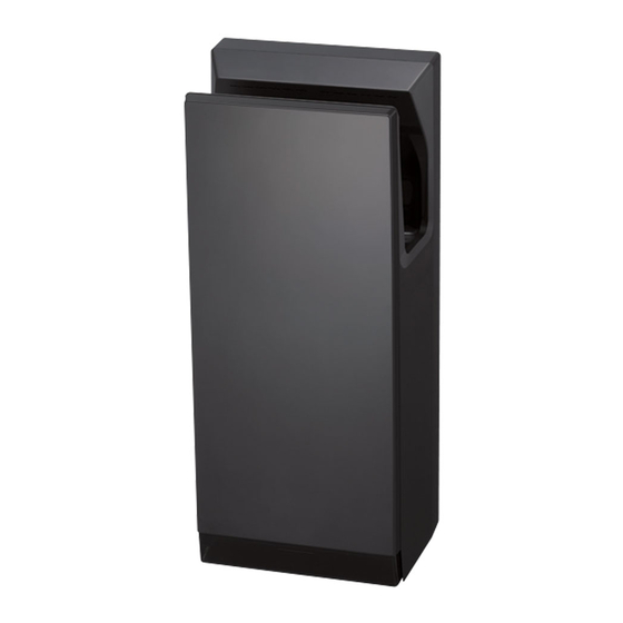
MODEL
JT-SB216JSH-W-E
JT-SB216JSH-H-E
JT-SB216JSH-S-E
JT-SB216KSN-W-E Heater-less Model
Appliance color W
INSTALLATION MANUAL
Read this manual thoroughly before beginning installation to ensure the appliance is installed safely and correctly.
Local installation standards should be obeyed and installation should be performed by the dealer or a qualified
professional.
The "INSTRUCTION MANUAL" is for the customer. Be sure to hand it to the customer.
INDEX
Safety Precautions
Pre-installation checks
Checking the installation environment
Checking the appliance, accessories, and items required for installation
Names of parts and external dimensions
Installation conditions
Required space for installation
Suitable walls
Making the appliance easier to use
Installation method
Test Run
Hand dryer
Heater Model
, H
, S
(White)
(Dark grey)
(Silver)
For Dealers and Installers
1
Model Name
Display Position
Power voltage
display position.
Single-phase 220-240VAC
2
3
3
3
4
5
5
5
5
6~10
11
1109875HD4101
GB
Table of Contents

Related Manuals for Mitsubishi Electric JT-SB216JSH-W-E


Summary of Contents for Mitsubishi Electric JT-SB216JSH-W-E
- Page 1 1109875HD4101 Hand dryer MODEL Model Name Display Position JT-SB216JSH-W-E Heater Model Power voltage display position. JT-SB216JSH-H-E JT-SB216JSH-S-E JT-SB216KSN-W-E Heater-less Model Appliance color W (White) (Dark grey) (Silver) Single-phase 220-240VAC INSTALLATION MANUAL For Dealers and Installers Read this manual thoroughly before beginning installation to ensure the appliance is installed safely and correctly.
-
Page 2: Safety Precautions
Safety Precautions Warning The following may lead to death or serious personal injury if the appliance is handled incorrectly. Do not install in locations where salt damage may occur, or where corrosive, neutral, or reductive gases are present. Electrical wiring work should be done by a certified professional in conformance with the technical This may cause malfunctions. -
Page 3: Pre-Installation Checks
Pre-installation checks Checking the installation environment Do not install in the following types of location. (This may cause malfunctions.) Outdoors Locations where the temperature could be lower than 0ºC. Locations where there is a lot of dust Locations where the temperature could be higher than 40ºC Locations where there is a lot of condensation Locations where salt damage could occur Vehicles (including ships and airplanes) -
Page 4: Names Of Parts And External Dimensions
Names of parts and external dimensions Terminal block 50 (Insertable dimensions) Installation panel Power cable hole (rear) Terminal block Drain tank Air filter (air intake) 103.5 79.5 Maximum width Unit (mm) of main unit Front Power control section Switch door Terminal block Front panel P o w e... -
Page 5: Installation Conditions
Installation conditions Required space for installation Wall Be sure to secure at least the distances Cautions listed in the right-hand table from walls, Right flammable (combustible) materials and Left so on. Location Clearance Ensure a distance of at least 130mm from the floor. -
Page 6: Installation Method
Installation method Caution Warning Use single phase 220 240V power. Do not install when the product (power cable) is electrified. Using the incorrect power supply may cause fires, electric shocks or malfunctions. Doing so may result in electric shocks. Check Single phase 220 240V power is being used. - Page 7 Installation (Continued) 1.Remove the drain tank and air filter. Drain tank Air filter 2.Remove the front panel mounting screws (2), and remove the front panel. Groove Front panel mounting screws Front panel 3.Remove the terminal cover mounting screw (1), Rubber bushing and remove the terminal cover.
- Page 8 Installation (Continued) Run the power cable through the hole in the back Hole of the appliance, and pull it through the appliance. Power cable Power cable Warning Use single phase 220 240V power. Using the incorrect power supply may cause fires, electric shocks or malfunctions.
- Page 9 Installation (Continued) Terminal Move the power block 1.Run the power cable through the rubber cable to the left side of the bushing, and attach the rubber bushing to terminal cover. the terminal cover. Terminal cover 2.Attach the terminal cover to the main unit mounting screw using the terminal cover mounting screw.
- Page 10 Switching the air speed switch and heater switch settings Check the heater ON/OFF settings and air speed HIGH/STANDARD settings with the customer beforehand. (The user cannot adjust the settings after installation is complete.) (The JT-SB216KSN-W-E does not have an air volume switch or heater switch.) Do not install when the product (power cord) is electrified.
-
Page 11: Test Run
Test Run Step What to check for Check Is single phase 220 240V power being used? Check the power supply voltage Incorrect power supply may cause malfunctions. Turn the ground-fault circuit interrupter on Turn the power switch "ON". Is the power lamp in the display on? Insert your hands to check if air is Is the air blowing? being blown. - Page 12 2006/66/EC Article 20 Information for end-users and Annex II. Français English Votre produit Mitsubishi Electric est conçu et fabriqué avec des matériels et des composants de qualité supérieure qui peuvent être Your MITSUBISHI ELECTRIC product is designed and recyclés et/ou réutilisés.
- Page 13 Var snäll och hjälp oss att bevara miljön vi lever i! Nederlands Dansk Mitsubishi Electric producten zijn ontwikkeld en gefabriceerd uit Dit produkt fra MITSUBISHI ELECTRIC er designet og fremstillet eerste kwaliteit materialen. De onderdelen kunnen worden med kvalitetsmaterialer og komponenter, der kan genindvindes gerecycled en/of worden hergebruikt.