Sony Mz-G750 Service Manual
Fm/am portable minidisc recorder
Hide thumbs
Also See for Mz-G750:
- Manual de instruções (148 pages) ,
- Operating instructions manual (99 pages) ,
- Specifications (2 pages)
Table of Contents
SERVICE MANUAL
Ver 1.1 2001. 02
Ver 1.0 2001. 01
US and foreign patents licensed from Dolby
Laboratories Licensing Corporation.
MD recorder
Audio playing system
MiniDisc digital audio system
Laser diode properties
Material: GaAlAs MQW
Wavelength: λ = 790 nm
Emission duration: continuous
Laser output: less than 44.6 µW
(This output is the value measured at a
distance of 200 mm from the lens surface
on the optical pick-up block with 7 mm
aperture.)
Recording and playback time
When using MDW-80
Maximum 160 min. in monaural
Maximum 320 min. in stereo
Revolutions
350 rpm to 2,800 rpm (CLV)
Error correction
ACIRC (Advanced Cross Interleave Reed
Solomon Code)
Sampling frequency
44.1 kHz
Sampling rate converter
Input: 32 kHz/44.1 kHz/48 kHz
Coding
ATRAC (Adaptive TRansform Acoustic
Coding)
ATRAC3-LP2
ATRAC3-LP4
Sony Corporation
9-873-045-12
2001B0400-1
Audio Entertainment Group
© 2001. 2
General Engineering Dept.
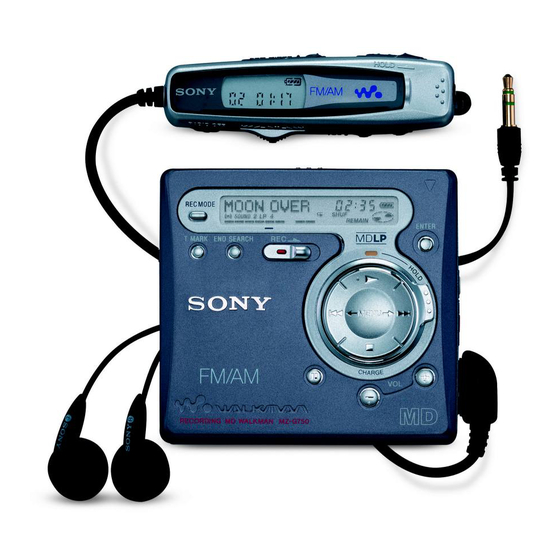
MZ-G750/R700
(Photo: MZ-G750)
SPECIFICATIONS
Modulation system
EFM (Eight to Fourteen Modulation)
Number of channels
2 stereo channels
1 monaural channel
Frequency response
20 to 20,000 Hz ± 3 dB
Wow and Flutter
Below measurable limit
Inputs
Microphone: stereo mini-jack, minimum
input level 0.25 mV
Line in: stereo mini-jack, minimum input
level 49 mV
Optical (Digital) in: optical (digital) mini-
jack
Outputs
i: stereo mini-jack, maximum output level
5 mW + 5 mW, load impedance 16 ohm
Radio (MZ-G750)
Frequency range
AM: 530-1,710 kHz (US,Canada, and
Central and South America models)
531-1,602 kHz (Other models)
FM: 87.5-108.0 MHz
FM/AM PORTABLE MINIDISC RECORDER
PORTABLE MINIDISC RECORDER
Canadian Model
Australian Model
Chinese Model
Model Name Using Similar Mechanism
Mechanism Type
Optical Pick-up Name
General
Power requirements
Sony AC Power Adaptor (supplied)
connected at the DC IN 3 V jack:
120 V AC, 60 Hz (U.S.A.,Canadian and
Taiwan model)
230 V AC, 50/60 Hz (AEP model)
240 V AC, 50 Hz (Australian model)
220 V AC, 50 Hz (Chinese model)
230-240 V AC, 50 Hz (UK and Hong
Kong model)
220 V AC, 50 Hz (Argentina model)
110/220 V AC, 60 Hz (Korean model)
100-240 V AC, 50/60 Hz (Other models)
Nickel cadmium rechargeable battery
NC-WMAA (supplied)
LR6 (size AA) alkaline battery (not
supplied)
US Model
AEP Model
UK Model
E Model
Tourist Model
NEW
MT-MZR700-172
LCX-4R
– Continued on next page –
MZ-G750
MZ-R700
1
Table of Contents

Related Manuals for Sony Mz-G750


Summary of Contents for Sony Mz-G750
- Page 1 Audio playing system EFM (Eight to Fourteen Modulation) Power requirements Number of channels MiniDisc digital audio system Sony AC Power Adaptor (supplied) Laser diode properties 2 stereo channels connected at the DC IN 3 V jack: Material: GaAlAs MQW 1 monaural channel 120 V AC, 60 Hz (U.S.A.,Canadian and...
- Page 2 Measured in accordance with the EIAJ (Electronic Industries damaged by heat. Association of Japan) standard. When using a 100% fully charged rechargeable battery. When using a Sony LR6 (SG) “STAMINA” alkaline dry battery (produced in Japan). CAUTION Recording time may differ according to the alkaline batteries.
-
Page 3: Table Of Contents
5-1. Outline ................18 5-2. Precautions for Adjustment ..........18 2. GENERAL 5-3. Adjustment Sequence ............18 Looking at the Controls (MZ-G750) ........5 5-4. NV Reset ................18 Looking at the Controls (MZ-R700) ........6 5-5. Power Supply Manual Adjustment ........19 5-6. -
Page 4: Servicing Note
MZ-G750/R700 SECTION 1 SERVICING NOTE • In performing the repair with the power supplied to the set, NOTES ON HANDLING THE OPTICAL PICK-UP removing the MAIN board causes the set to be disabled. BLOCK OR BASE UNIT In such a case, fix a convex part of the open/close detect switch The laser diode in the optical pick-up block may suffer electro- (S806 on MAIN board) with a tape in advance. -
Page 5: General
MZ-G750/R700 SECTION 2 GENERAL This section is extracted from instruction manual. (MZ-G750) -
Page 6: Looking At The Controls (Mz-R700)
MZ-G750/R700 (MZ-R700) -
Page 7: Disassembly
MZ-G750/R700 SECTION 3 DISASSEMBLY Note : This set can be disassemble according to the following sequence. Panel Assy,Lower Panel Assy, Upper LCD Module Main Board MD Mechanism Deck Service Assy, OP Holder Assy Motor Flexible Board Motor, DC (M602) Motor, DC (M601), Motor, DC (M603) Note : Follow the disassembly procedure in the numerical order given. -
Page 8: Lcd Module
MZ-G750/R700 3-3. LCD MODULE 2 screws (1.7x2.5) 1 screws (1.7x2.5) 4 LCD module claws panel assy, upper 3-4. MAIN BOARD 8 CN501 4 screws (M1.7x3) 6 Remove the solders 2 arm 3 screws (M1.4x2) qa Remove the solder qd MAIN board 5 screws (M1.4x2) -
Page 9: Md Mechanism Deck
MZ-G750/R700 3-5. MD MECHANISM DECK 3 MD mechanism deck boss boss 2 chassis assy, set 1 screws (1.4x1.6), MI 3-6. SERVICE ASSY, OP 3 screw(M1.4), 1 washer (0.8 - 2.5) 5 screw(M1.4), precision pan precision pan 2 gear (SA) 6 spring, thrust detent... -
Page 10: Holder Assy
MZ-G750/R700 3-7. HOLDER ASSY 4 Remove the holder assy to direction of the arrow B . 1 Open the holder assy. 3 boss 3-8. MOTOR FLEXIBLE BOARD 1 Remove four solders of DC motor (sled) (M602). 2 Remove two solders of DC motor (over write head up/down) (M603). -
Page 11: Motor, Dc (M602)
MZ-G750/R700 3-9. MOTOR, DC (M602) 3 Remove four solders of motor flexible board. 4 two screws(M1.4), 1 washer (0.8 - 2.5) precision pan 2 gear (SA) 5 moter, DC (sled) (M602) 3-10. “MOTOR, DC (M601)”, “MOTOR, DC (M603)” 1 Remove six solders of motor flexible board. -
Page 12: Test Mode
MZ-G750/R700 SECTION 4 TEST MODE 4-1. Outline 4-3. Operation in Setting the Test Mode • This set provides the Overall adjustment mode that allows CD • When the test mode becomes active, first the display check mode and MO discs to be automatically adjusted when in the test mode. -
Page 13: Configuration Of Test Mode
MZ-G750/R700 4-5. Configuration of Test Mode VOL + key: 100th Place of item number Major item switching increase. Test mode (Display Check Mode) VOL – key: 100th Place of item number Press the > or VOL + decrease. N key... -
Page 14: Overall Adjustment Mode
MZ-G750/R700 5. The display changes a shown below each time the 4-8. Self-Diagnosis Result Display Mode [ENTER] key on the set is pressed. This set uses the self-diagnostic function system in which if an error occurred during the recording or playing, the mechanism... -
Page 15: Result The Error Display Code
MZ-G750/R700 • Description of Error Indication Codes Problem Indication code Meaning of code Simple display Description No error No error No error Illegal access target Adrs Attempt to access an abnormal address address was specified Servo system error High temperature... -
Page 16: Sound Skip Check Result Display Mode
MZ-G750/R700 4-10. Sound Skip Check Result Display Mode • Cause of Sound Skip Error This set can display the count of errors that occurred during the Cause of error Description of error recording/playing for checking. Sound error correction error • Setting method of sound skip check result display... - Page 17 MZ-G750/R700 4. When all the keys on the set and on the remote commander are considered as OK, the following displays are shown for 4 sec- onds. Example1: When the keys on the set are considered as OK: This set LCD display...
-
Page 18: Electrical Adjustments
3. Press the key once more. • Test CD disc TDYS-1 (Part No. : 4-963-646-01) This set LCD display • SONY MO disc available on the market 0 21 • Digital voltmeter • Laser power meter LPM-8001 (Part No. : J-2501-046-A) NV reset(after several seconds) •... -
Page 19: Power Supply Manual Adjustment
MZ-G750/R700 3) Press the key to write the adjusted value. • Adjustment method of Vc PWM Duty (L) 4) Select the manual mode of the test mode, and set item number (item number: 762) 862 (see page 13). This set LCD display... -
Page 20: Temperature Correction
MZ-G750/R700 1. Connect a digital voltmeter to the TP902 (VL) on the MAIN 2. Press the key continuously until the optical pick-up [VOL +] [VOL --] board, and adjust key (voltage up) or moves to the most inward track. (voltage down) so that the voltage becomes 2.30 ± 0.01 V. -
Page 21: Overall Adjustment Mode
MZ-G750/R700 Adjustment/checking and Connection Location: 5-8. Overall Adjustment Mode • Configuration of overall adjustment –MAIN BOARD(SIDE A)– . key Overall adjustment mode (Title display) N key Protect switch CD overall adjusting All item NG item exists or x key CD overall... - Page 22 MZ-G750/R700 • Overall Adjustment Mode (Title Display) • Adjustment Method of Overall CD and MO Adjustment Mode This set LCD display 1. Setting the test mode (see page 12). 0 00 [VOL --] Assy 2. Press the key activates the overall adjust- ment mode.
-
Page 23: Resume Clear
MZ-G750/R700 • Overall CD and MO adjustment items 5-9. Resume Clear 1. Overall CD adjustment items Perform the Resume clear when all adjustments completed. Item No. Description • Resume Clear Setting Method 1. Select the manual mode of the test mode, and set item number CD electrical offset adjustment 043 (see page 13). - Page 24 MZ-G750/R700 [VOL+] [VOL--] • Modified Data Writing Method (version 1.000) 12. Adjust with the key (adjusted value up) or 1. Select the manual mode of the test mode, and set item number key (adjusted value down) so that the adjusted value becomes 023 (see page 13).
- Page 25 MZ-G750/R700 This set LCD display This set LCD display 0 23 0 23 0D61A1 A1: Adjusted value DD: Adjusted value 25. Press the key. 37. Turn the power off. (0D61 is blinking) [VOL+] 26. Press the key once to change the blinking portion to •...
- Page 26 MZ-G750/R700 24. Press the key. This set LCD display (0D65 is blinking) 0 23 0D5E04 [VOL+] 25. Press the key once to change the blinking portion to 0D66. This set LCD display 04: Adjusted value 0 23 0D6600 12. Press the key.
- Page 27 MZ-G750/R700 36. Press the key. 48. Press the key. (0D69 is blinking) (0D6E is blinking) [VOL+] [VOL+] 37. Press the key to change the blinking portion to 0D6C. 49. Press the key to change the blinking portion to 0D72. This set LCD display...
- Page 28 MZ-G750/R700 60. Press the key. 72. Press the key. (0D65 is blinking) (0D78 is blinking) [VOL+] [VOL+] 61. Press the key once to change the blinking portion to 73. Press the key once to change the blinking portion to 0D75.
-
Page 29: Diagrams
MZ-G750/R700 SECTION 6 DIAGRAMS 6-1. IC PIN FUNCTION DESCRIPTION • IC501 SN761057DBT (RF AMP, FOCUS/TRACKING ERROR AMP) Pin No. Pin Name Description Tracking error signal output to the system controller (IC801) REXT — Connect terminal to the external resistor for ADIP amp control WPPLPF —... - Page 30 MZ-G750/R700 • IC801 CXD2671-204GA (SYSTEM CONTROLLER, DIGITAL SIGNAL PROCESSOR, 16M BIT D-RAM) Pin No. Pin Name Description PAUSE KEY Set key input terminal (X key input) Control signal output to the microphone amp MIC SENSE “H”: HIGH, “L”: LOW, normally: “H”...
- Page 31 MZ-G750/R700 Pin No. Pin Name Description AVD2 — Power supply terminal (for the analog) (+2.4 V) AVS2 — Ground terminal (for the analog) ADRB A/D converter the lower limit voltage input (fixed at “L” in this set) Sled error signal input terminal Not used (fixed at “L”)
- Page 32 MZ-G750/R700 Pin No. Pin Name Description Sled motor drive signal output (W) to the motor driver (IC551)/drive control signal SLDW output (2+) SLCU Spindle motor drive comparison signal input (U) from the motor driver (IC551) SLCV Spindle motor drive comparison signal input (V) from the motor driver (IC551)
- Page 33 MZ-G750/R700 Pin No. Pin Name Description Open/close detection switch (S806) of the upper panel input terminal (A/D input) OPEN CLOSE SW “L”: when upper panel close GND SW Control signal output to the ground (GND) changeover switch 172, 173 SET CODE0, 1 Input terminal for the set (fixed at “L”...
- Page 34 MZ-G750/R700 Pin No. Pin Name Description 224 – 226 (XAVLS), (SOUND 1, 2) Not used (open) XHOLD SW HOLD switch input terminal “L”: hold ON, “H”: hold OFF (SYCN REC) SYNCHRO REC switch input terminal “L”: OFF, “H”: ON Not used (open)
-
Page 35: Block Diagram - Servo Section
MZ-G750/R700 6-2. BLOCK DIAGRAM — SERVO SECTION — MAIN BOARD (1/3) SERVO SECTION MOTOR FLEXIBLE MECHANISM (1/2) BOARD (1/2) OVER WRITE HEAD DRIVE HD DRV+ M603 IC601(1/2) Signal path HD DRV– OVER WRITE HEAD CN502(1/2) : PLAYBACK UP/DOWN : REC(ANALOG IN) -
Page 36: Block Diagram - Audio Section
MZ-G750/R700 6-3. BLOCK DIAGRAM — AUDIO SECTION — MAIN BOARD (2/3)AUDIO SECTION OPTICAL RECEIVER OPT CONTROL VIF B+ SWITCH Q302 DIN1 J301 LINE IN (OPTICAL) SERVO (LINE IN JACK) SECTION (Page 35) MIC AMP IC303 J303 LIN2 OUT1 LIN1 (PLUG IN POWER) -
Page 37: Block Diagram - System Control/Power Section
MZ-G750/R700 6-4. BLOCK DIAGRAM — SYSTEM CONTROL / POWER SECTION — MAIN BOARD (3/3) SYSTEM CONTROL/POWER SECTION G750 Q1007 AUDIO RMC KEY R700 SECTION R920 (Page 36) VRMC R700 R1036 XWK3 RMC KEY CLK SEL CLK SEL FFCLR FFCLR SLEEP... -
Page 38: Printed Wiring Board - Main Section
R1023 R1008 R1007 2 4 6 8 IC1002 (Q1010) TP333 IC1005 C558 TP1004 IC1004 (D-IN) J301(1/2) RB553 ) : MZ-G750 only IC551 C559 LINE IN TP332 D1003 1 3 5 7 (OPTICAL) C822 (DGND) G750 R815 TP1001 FB804 FB802 R831... - Page 39 C803 (MIC L) (Q1009) AP835 IC303 AP525 (XMICDET) R118 C508 C819 SL505 SL801 C118 R813 (TEST) AP535 C820 ) : MZ-G750 only C307 C302 C306 AP532 C806 J303 C509 SL506 R507 C501 C502 C216 AP817 AP802 IC801 AP526 C510 AP842...
- Page 40 MZ-G750/R700 Common note on Schematic Diagram: • Waveforms • All capacitors are in µF unless otherwise noted. pF: µµF 50 WV or less are not indicated except for electrolytics 100mV/DIV, 1µs/DIV and tantalums. • All resistors are in Ω and W or less unless otherwise Approx.
-
Page 41: Schematic Diagram - Main Section (1/3)
MZ-G750/R700 6-6. SCHEMATIC DIAGRAM — MAIN SECTION (1/3) — • Refer to page 40 for Waveforms. Refer to page 44 for IC Block Diagrams. IC B/D 42 41 40 39 38 37 36 35 34 33 32 31 30 29... -
Page 42: Schematic Diagram - Main Section (2/3)
MZ-G750/R700 6-7. SCHEMATIC DIAGRAM — MAIN SECTION (2/3) — • Refer to page 40 for Waveforms. Refer to page 44 for IC Block Diagrams. 181 180 179 176 175 174 172 171 170 168 167 166 (Page 43) (Page 41) -
Page 43: Schematic Diagram - Main Section (3/3)
MZ-G750/R700 6-8. SCHEMATIC DIAGRAM — MAIN SECTION (3/3) — • Refer to page 44 for IC Block Diagrams. R104,204 Except US model:10k US model: 33k IC B/D C101,201 Except US model:2.2 US model: 0.47 IC B/D IC B/D IC B/D... - Page 44 PRE DRIVER PRE DRIVER PD-O 3PHASE CONTROL XRST SERIAL SBUS ADIP 2 3 4 5 ADIP DVDD IC303 NJM2173AV IC1002 XC61CN1102MR (MZ-G750) IC1006 XC6371C271PR (MZ-G750) IC1004 XC61CN1702MR (MZ-G750) IC1005 XC61CN1002MR (MZ-G750) VOUT OUT2 CUT2 STBY CHIP ENABLE VREF VREF PHASE SLOW...
- Page 45 MZ-G750/R700 IC601 XPC18A22FCR2 VC2 VG OUTPUT SW OUTPUT SW CHARGE CHARGE PUMP 1 PUMP 2 VC VG DC IN HI-BRIDGE CHARGE PRE DRIVER PRE DRIVER MONITOR VREF VREF X2/X4 BATM BUFFER DC IN CVREF CONTROL CONTROL CHARGE CHGSW DW BT...
- Page 46 MZ-G750/R700 IC301 AK5354VT CONTROL REGISTER CCLK CDTI LRCK MCLK CLOCK DIVIDER LIN1 BCLK IPGA AUDIO I/F SDTO CONTROLLER RIN1 LIN2 RIN2 VCON VCON AGND IC302 TA2131FL BEEP V REF VREF LPF1 TCMT IN R BST1 IN L LPF2 OUTB BST2...
-
Page 47: Exploded Views
MZ-G750/R700 SECTION 7 EXPLODED VIEWS NOTE: • The mechanical parts with no reference • Accessories and packing materials are The components identified by mark 0 or dotted line with mark number in the exploded views are not supplied. given in the last of this parts list. -
Page 48: Chassis Section
MZ-G750/R700 7-2. CHASSIS SECTION MT-MZR700-172 Ref. No. Part No. Description Remark Ref. No. Part No. Description Remark X-3379-555-1 CHASSIS ASSY, SET 3-222-780-01 SPRING, TORSION 3-222-779-01 SPRING (OPEN), TENSION 4-218-233-09 SCREW (1.7), MI * 53 A-3323-650-A MAIN BOARD, COMPLETE (R700:CND,AEP,UK,E, 3-335-797-01 SCREW (M1.4X2), TOOTHED LOCK AUS,EE,JE,FR,AR,HK,CH,TW,KR) 3-318-382-01 SCREW (1.7X3), TAPPING... -
Page 49: Md Mechanism Deck Section
MZ-G750/R700 7-3. MD MECHANISM DECK SECTION (MT-MZR700-172) M603 M602 M601 The components identified by Les composants identifiés par une mark 0 or dotted line with mark marque 0 sont critiques pour la 0 are critical for safety. sécurité. Replace only with part number Ne les remplacer que par une piéce... -
Page 50: Electrical Parts List
MZ-G750/R700 SECTION 8 MAIN ELECTRICAL PARTS LIST NOTE: • Due to standardization, replacements in • Items marked “*” are not stocked since The components identified by mark 0 or dotted line with mark the parts list may be different from the they are seldom required for routine service. - Page 51 MZ-G750/R700 MAIN Ref. No. Part No. Description Remark Ref. No. Part No. Description Remark C521 1-125-777-11 CERAMIC CHIP 0.1uF C808 1-164-850-11 CERAMIC CHIP 10PF 0.5PF C522 1-125-777-11 CERAMIC CHIP 0.1uF C809 1-135-259-11 TANTAL. CHIP 10uF 6.3V C523 1-125-837-11 CERAMIC CHIP 6.3V...
- Page 52 MZ-G750/R700 MAIN Ref. No. Part No. Description Remark Ref. No. Part No. Description Remark C1007 1-117-919-11 TANTAL. CHIP 10uF 6.3V FB804 1-216-864-11 SHORT (G750) FB805 1-216-864-11 SHORT C1008 1-117-919-11 TANTAL. CHIP 10uF 6.3V (G750) < IC > C1009 1-117-919-11 TANTAL. CHIP 10uF 6.3V...
- Page 53 MZ-G750/R700 MAIN Ref. No. Part No. Description Remark Ref. No. Part No. Description Remark Q302 8-729-046-49 FET FDV304P R317 1-218-941-11 RES-CHIP 1/16W Q501 8-729-922-10 TRANSISTOR 2SA1577-QR R318 1-218-953-11 RES-CHIP 1/16W Q601 8-729-046-45 FET SI2302DS-T1 R319 1-218-953-11 RES-CHIP 1/16W Q602 8-729-046-44 TRANSISTOR ZDT6718TA...
- Page 54 MZ-G750/R700 MAIN Ref. No. Part No. Description Remark Ref. No. Part No. Description Remark R837 1-218-990-11 SHORT R1022 1-208-947-11 METAL CHIP 330K 0.5% 1/16W R839 1-208-939-11 METAL CHIP 150K 0.5% 1/16W (G750) R840 1-216-809-11 METAL CHIP 1/16W R1023 1-208-683-11 METAL CHIP 0.5%...
- Page 55 MZ-G750/R700 Ref. No. Part No. Description Remark Ref. No. Part No. Description Remark MISCELLANEOUS 3-223-666-71 MANUAL, INSTRUCTION (ENGLISH, TRADITIONAL CHINESE,KOREAN) *************** (R700:E,JE,HK,TW,KR) 1-476-305-11 LCD MODULE (G750) 3-223-666-81 MANUAL, INSTRUCTION (ENGLISH, 1-804-198-11 LCD MODULE (R700) SIMPLIFIED CHINESE) (R700:CH) 1-679-372-11 FLEXIBLE BOARD...
- Page 56 MZ-G750/R700 REVISION HISTORY Clicking the version allows you to jump to the revised page. Also, clicking the version at the upper right on the revised page allows you to jump to the next revised page. Ver. Date Description of Revision 2001.