Table of Contents
Table of Contents

Related Manuals for Bosch PLN-24CH12


Summary of Contents for Bosch PLN-24CH12
- Page 1 Battery Charger PLN-24CH12 and PRS-48CH12 Installation and Operation manual...
-
Page 3: Table Of Contents
EN54-4 labeling Connection Connecting the battery Connection specifications Connect the back-up power Connect the auxiliary power Connect the output contacts Connect the temperature sensor Connect the mains Bosch Security Systems B.V. Installation and Operation manual 180110011Aa | V1.1 | 2011.05... - Page 4 11.1.1 General 11.1.2 Fuses 11.2 Mechanical 11.3 Environmental conditions 11.4 Approvals and compliance with standards 11.4.1 Safety approvals 11.4.2 EMC approvals 11.4.3 Voice Alarm System related approvals 180110011Aa | V1.1 | 2011.05 Installation and Operation manual Bosch Security Systems B.V.
-
Page 5: Safety
Interventions with the equipment switched on are authorized only when it is impossible to switch the equipment off. The operation must only be performed by qualified personnel. Bosch Security Systems B.V. Installation and Operation manual 180110011Aa | V1.1 | 2011.05... -
Page 6: Short Information
The equipment or the property can be seriously damaged, or persons can be severely injured if the alert is not observed. DANGER! Not observing the alert can lead to severe injuries or death. 180110011Aa | V1.1 | 2011.05 Installation and Operation manual Bosch Security Systems B.V. -
Page 7: Conversion Tables
Table 2.3 Conversion of units of pressure NOTICE! 1 hPa = 1mbar. Fahrenheit Celsius °F = 9/5 (°C + 32) °C = 5/9 (°F - 32) Table 2.4 Conversion of units of temperature Bosch Security Systems B.V. Installation and Operation manual 180110011Aa | V1.1 | 2011.05... -
Page 8: System Overview
System Overview Application The PLN-24CH12 (24 Vdc) and the PRS-48CH12 (48 Vdc) battery charger is intended for a Voice Alarm System. The battery chargers are microprocessor based devices that have been designed to charge lead-acid batteries (back-up batteries connected to the Voice Alarm System) and, simultaneously, to provide power to auxiliary applications. -
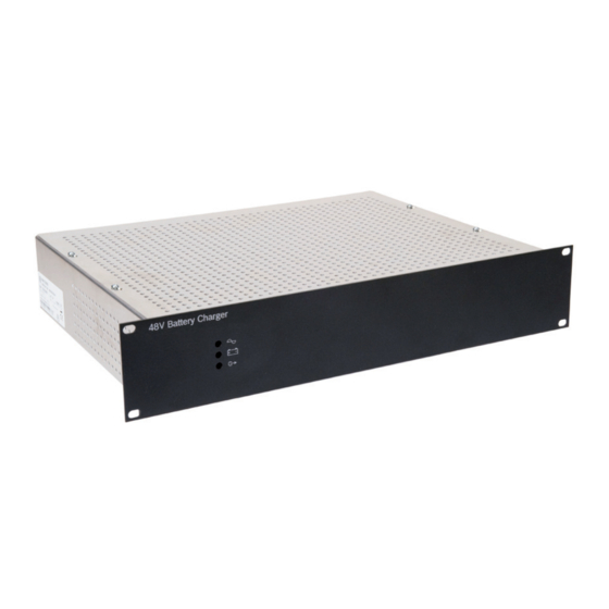
Page 9: Product View
- When the mains is present and the battery voltage during start-up is: PLN-24CH12: Vbat ≤ 14 Vdc, Vbat ≥ 30 Vdc (±3%) PRS-48CH12: Vbat ≤ 40 Vdc, Vbat ≥ 60 Vdc (±3%) - When battery is connected in reverse when... -
Page 10: Connections On The Rear Panel
- Mains status (5 sec. of delay after mains fault) - Battery status - Output voltage status Battery terminal Terminal for connecting the battery leads (150 A max.). 180110011Aa | V1.1 | 2011.05 Installation and Operation manual Bosch Security Systems B.V. -
Page 11: Planning Information
"20 hour rate". This means that it is discharged down to 10.5 V over a 20 hour period while the total actual amp-hours it supplies is measured. Bosch Security Systems B.V. Installation and Operation manual... -
Page 12: Effects Of Discharge Rate On Battery Capacity And Battery Life
Figure 4.2 shows how the battery life is affected by the depth of discharge. Figure 4.2 Battery life based on depth of discharge Number of cycles Daily average depth of discharge in % 180110011Aa | V1.1 | 2011.05 Installation and Operation manual Bosch Security Systems B.V. -
Page 13: State Of Charge
C to 2.3 V per cell at 50 C. This is why temperature compensation (see section 8.1.4 ) on your battery charger must always be enabled, except for testing, maintenance, etc. Bosch Security Systems B.V. Installation and Operation manual 180110011Aa | V1.1 | 2011.05... -
Page 14: Battery Self-Discharging
(lead-antimony plates) have the highest self- discharge. In systems that are continually connected to some type of charging source, like the Bosch Battery Charger, this is not a problem. However, one of the biggest killers of batteries is sitting stored in a partly discharged state for a few months, like before commissioning. -
Page 15: Sealed Gel Cell
For use in a system where discharge rates are less than severe, gel batteries could be a good choice. Bosch Security Systems B.V. Installation and Operation manual 180110011Aa | V1.1 | 2011.05... -
Page 16: Installation
For each battery charger type a jumper is located at the daughter board to set trigger thresholds for the resistance and allowed discharge current. Figure 5.1 Location of the battery jumper of the PLN-24CH12 (similar location for the PRS-48CH12) Jumper setting... -
Page 17: Rack Mounting
The openings provided in the cabinet must be kept free. Do not create additional openings because this can cause the device to malfunction and voids the warranty. Bosch Security Systems B.V. Installation and Operation manual 180110011Aa | V1.1 | 2011.05... -
Page 18: En54-4 Labeling
| Installation Battery Charger EN54-4 labeling Please affix the regarding label clearly visible on the cabinet after installation. 180110011Aa | V1.1 | 2011.05 Installation and Operation manual Bosch Security Systems B.V. -
Page 19: Connection
Battery Charger Connection | en Connection Faux3 Faux2 Faux1 Figure 6.1 Block diagram of the battery charger. Refer to table 6.1. Bosch Security Systems B.V. Installation and Operation manual 180110011Aa | V1.1 | 2011.05... - Page 20 | Connection Battery Charger Figure 6.2 Top view PLN-24CH12 (24 Vdc). Refer to table 6.1. Figure 6.3 Top view PRS-48CH12 (48 Vdc). Refer to table 6.1. 180110011Aa | V1.1 | 2011.05 Installation and Operation manual Bosch Security Systems B.V.
- Page 21 Daughter board Battery fuse breaker (Not included. Installed outside the battery charger) Battery relay Mains fuse (6.3 A for PLN-24CH12) or (8 A for PRS-48CH12) Power supply fuse (12.5 A) Table 6.1 Valid for figure: 6.1, 6.2 and 6.3. Bosch Security Systems B.V.
-
Page 22: Connecting The Battery
Connecting the battery CAUTION! For the PLN-24CH12 Battery Charger, the total sum of the batteries must be equal to 24 Vdc. For the PRS-48CH12 Battery Charger, the total sum of the batteries must be equal to 48 Vdc. When connecting multiple batteries, observe the following: –... -
Page 23: Connect The Back-Up Power
Status LED Output contact Green Yellow Mains status C-NO C-NC Battery status C-NO C-NC Output voltage status C-NO C-NC Table 6.2 Output contact status vs LED indication Bosch Security Systems B.V. Installation and Operation manual 180110011Aa | V1.1 | 2011.05... -
Page 24: Connect The Temperature Sensor
Make sure that the safety ground is connected to the battery charger via the mains power cable. CAUTION! Do not make a separate ground connection to the battery. 180110011Aa | V1.1 | 2011.05 Installation and Operation manual Bosch Security Systems B.V. - Page 25 Battery Charger Connection | en CAUTION! Do not make a separate ground connection to the 24 Vdc or 48 Vdc output terminal. The outputs have a common return. Bosch Security Systems B.V. Installation and Operation manual 180110011Aa | V1.1 | 2011.05...
-
Page 26: Configuration
The following batteries are approved: – Yuasa NPL series – Powersonic GB series – ABT TM series – Enersys VE series – Effekta BTL series – Long GB series. 180110011Aa | V1.1 | 2011.05 Installation and Operation manual Bosch Security Systems B.V. -
Page 27: Operation
(refer to section 3.4.1 ). Refer to section 5.1 for Ri threshold levels. 8.1.2 Battery undervoltage protection The voltage threshold V is 21.6 Vdc ±3% for PLN-24CH12 or 43.2 Vdc ±3% for PRS- final 48CH12. Discharging when the mains power (Vac) is not present on the battery charger... -
Page 28: Charging
Figure 8.2 Charger voltage vs time Bulk mode. Float mode. I bat Figure 8.3 Charge current vs time Bulk mode (in this mode the current is controlled). Float mode. 180110011Aa | V1.1 | 2011.05 Installation and Operation manual Bosch Security Systems B.V. -
Page 29: Battery Temperature Compensation
27.2 / 54.4 26.2 / 52.4 Temp Figure 8.4 Temperature compensation for Vfloat The temperature compensation for V float For PLN-24CH12: -40 mV / C @ 25 For PRS-48CH12: -80 mV / C @ 25 Commissioning the system NOTICE! To avoid start-up problems of the battery charger, the main and auxiliary output current should be <... -
Page 30: Troubleshooting
Ensure that the battery charger was handled with care and without heavy bumps during transport. 180110011Aa | V1.1 | 2011.05 Installation and Operation manual Bosch Security Systems B.V. -
Page 31: Maintenance
Replacing the original battery with a battery of incorrect type may result in an explosion hazard. Used batteries must be disposed of in compliance with recycling requirements. Bosch Security Systems B.V. Installation and Operation manual 180110011Aa | V1.1 | 2011.05... -
Page 32: Technical Data
11.1.1 General Mains input voltage 195 - 264 Vac, 47/63 Hz Power consumption at full load 380 W (PLN-24CH12 Battery Charger) Power consumption at full load 760 W (PRS-48CH12 Battery Charger) Maximum primary current at 195 V (PLN-24CH12 Battery Charger) -
Page 33: Mechanical
EN54-4: 1997 and amendment A2 (February 2006): Fire detection and fire alarm systems (Part 4: Power supply equipment). – CE CPD Numbers are: 0333-CPD-075381-1 (PLN-24CH12) and 0333-CPD-075383-1 (PRS-48CH12). They have been affixed in 2011. – EN 12101-10 class A (January 2006): Smoke and heat control systems. Part 10: power supplies. - Page 35 Bosch Security Systems B.V. Kapittelweg 10 4827 HG Breda The Netherlands www.boschsecurity.com © Bosch Security Systems B.V., 2011...