Table of Contents
INSTALLATION MANUAL
AIR CONDITIONER
• Please read this installation manual completely before installing the product.
• Installation work must be performed in accordance with the national wiring
standards by authorized personnel only.
• Please retain this installation manual for future reference after reading it
thoroughly.
TYPE : Multi Type
P/NO : MFL67206502
http://www.lghvac.com
www.lg.com
Table of Contents

Related Manuals for LG FLEX MULTI SPLIT


Summary of Contents for LG FLEX MULTI SPLIT
-
Page 1: Installation Manual
• Please read this installation manual completely before installing the product. • Installation work must be performed in accordance with the national wiring standards by authorized personnel only. • Please retain this installation manual for future reference after reading it thoroughly. TYPE : Multi Type http://www.lghvac.com www.lg.com P/NO : MFL67206502... - Page 2 FLEX MULTI SPLIT INSTALLATION INSTRUCTIONS...
-
Page 3: Table Of Contents
Multi Air Conditioner Installation Manual TABLE OF CONTENTS Required Tools Installation Requirements Installation Parts Provided ...........4 Product Introduction .............5 Indoor Unit.................5 Outdoor Unit ..............5 o Level gauge Safety Precautions ..............6 o Screw driver Installation of Indoor, Outdoor Unit ........9 o Electric drill Select the best location ............9 o Hole core drill (ø50mm) Seaside Applications and Installation ......11... -
Page 4: Installation Parts Provided
Installation Parts Provided Installation Parts Provided [Standard / Standard Libero / Artcool Mirror] Type 1 Type 2 Type 3 Type 4 Installation plate Installation plate Installation plate Installation plate Type "B" screw Type "B" screw Type "B" screw Type "C" screw Type "B"... -
Page 5: Product Introduction
Product Introduction Product Introduction Here is a brief introduction of the indoor and outdoor units. Please see the information specific to your indoor unit type. Indoor Unit [Standard Type] [Artcool Mirror Type] Air inlet Grille tab Air inlet Plasma filter (Optional) Air filter Front grille ON/OFF button... -
Page 6: Safety Precautions
Safety Precautions Safety Precautions To prevent the injury of the user or other people and property damage, the following instructions must be followed. n Be sure to read before installing the air conditioner. n Be sure to observe the cautions specified here as they include important items related to safety. n Incorrect operation due to ignoring instruction will cause harm or damage. - Page 7 Safety Precautions Do not install the product at a place that there Use caution when unpacking and installing. is concern of falling down. • Otherwise, it may result in personal injury. • Sharp edges may cause injury. Use a vacuum pump or Inert (nitrogen) gas when doing leakage test or air purge. Do not compress air or Oxygen and Do not use Flammable gases.
- Page 8 Safety Precautions CAUTION n Installation Install the drain hose to ensure that drain Install the product so that the noise or hot can be securely done. wind from the outdoor unit may not cause any damage to the neighbors. • Otherwise, it may cause water leakage. •...
-
Page 9: Installation Of Indoor, Outdoor Unit
Installation of Indoor, Outdoor Unit Installation of Indoor, Outdoor Unit Read completely, then follow step by step. Select the best location Indoor unit 1. Do not have any heat or steam near the unit. [Standard/Standard Libero/Artcool Mirror/Artcool Libero Type] 2. Select a place where there are no obstacles More than in front of the unit. -
Page 10: Rooftop Installations
Installation of Indoor, Outdoor Unit Outdoor unit 1. If an awning is built over the unit to prevent di- rect sunlight or rain exposure, make sure that heat radiation from the condenser is not re- more than 300 more than 300 stricted. -
Page 11: Seaside Applications And Installation
Installation of Indoor, Outdoor Unit Seaside Applications and Installation 1. Air conditioners should not be installed in areas where corrosive gases, such as acid or alkaline gas, are produced. 2. Do not install the product where it could be exposed to sea wind (salty wind) directly. It can result corrosion on the product. -
Page 12: Piping Length And Elevation
Installation of Indoor, Outdoor Unit Piping length and elevation Multi Piping Type Unit : m(ft) Max total length Max Elevation Outdoor Unit Max length of Min length of Max elevation Max.Combination of all pipes between each Capacity each pipe each pipe between indoor of Indoor unit (A+B)/(A+B+C)/... - Page 13 Installation of Indoor, Outdoor Unit Distributor Piping Type Unit : m(ft) Min length of Max Elevation Max Eleva- Max total length Max length Max length Max Combi- Outdoor Unit Max length each pipe Between each tion of all pipes nation Capacity of each (Main /...
-
Page 14: Installation
Installation Installation [Standard / Standard Libero / Artcool Mirror Type] Connecting the piping # Standard / Artcool Mirror Type 1. Prepare the indoor unit's piping and drain hose for installation through the wall. 2. Remove the plastic tubing retainer(see the il- lustration on the right) and pull the tubing and drain hose away from chassis. - Page 15 Installation # Standard Libero / Artcool Libero Type 1. Pull the screw cap at the bottom of the indoor unit 2. Remove the chassis cover from the unit by loosing screws Chassis cover Indoor unit back side view 3. Pull back the tubing holder. Pipe Port 4.
-
Page 16: Good Case
Installation Connecting the piping to the indoor unit and drain hose to drain pipe. 1. Align the center of the pipes and suffi- Indoor unit tubing Flare nut Pipes ciently tighten the flare nut by hand. 2. Tighten the flare nut with a wrench. Open-end wrench (fixed) Outside diameter Torque... - Page 17 Installation Wrap the insulation material around the con- Plastic bands Insulation material necting portion. 1. Overlap the connection pipe insulation and the indoor unit pipe heat insulation material. Bind them together with vinyl tape so that there is no gap. Indoor unit pipe Connection pipe 2.
-
Page 18: How To Fix
Installation Installation of filters 1) Detach two attached tapes from the plasma filter. Plasma Filter How To Fix The wall you select should be strong and solid enough to prevent vibration 1. Mount the installation plate on the wall with type "A"... -
Page 19: Wiring Connection
Installation Wiring Connection 1. Connect the wires to the terminals on the con- trol board individually according to the outdoor unit connection. • Ensure that the color of the wires of outdoor unit and the terminal No. are the same as those of indoor unit respectively. -
Page 20: Ceiling Dimension And Hanging Bolt Location
Installation [Ceiling Concealed Duct Type] Ceiling dimension and hanging bolt location Installation of Unit Install the unit above the ceiling correctly. CASE 1 POSITION OF SUSPENSION BOLT • Apply a joint-canvas between the unit and duct to absorb unnecessary vibration. •... -
Page 21: How To Fix
Installation How to Fix • Select and mark the position for fixing • Insert the set anchor and washer onto the bolts. suspension bolts for locking the suspen- • Drill the hole for set anchor on the face of sion bolts on the ceiling. ceiling. - Page 22 Installation CAUTION 1. Install declination of the indoor unit is very important for the drain of the duct type air conditioner. 2. Minimum thickness of the insulation for the connecting pipe shall be 19mm(1/32 inch). Front of view • The unit must be horizontal or declined to the drain hose connected when fin- ished installation.
-
Page 23: Installation Of Wired Remote Controller
Installation Installation of wired Remote Controller Put the installation paper on the place and determine the position and height of the fixing screws of the wired re- mote controller. • Refer to the printed side of the installation paper. The position of the fixing screws Plug the connecting cable into the indoor unit. -
Page 24: Wired Remote Controller Switch Information
Installation Wired remote controller switch information Group control switch Group Control SWGR 1. For individual control/Master use 2. For group control/Slave use Ceiling height selection switch Ceiling Height/Default E.S.P SWHI 1. Low ceiling 2. Standard ceiling 3. High ceiling S/W 1 Select Product Product selection switch SWPD... -
Page 25: Trial Operation
Installation n Necessary functions before using Trial Operation The trial operation is to check the installation status of the product. The temperature will not be con- trolled during trial operation. Instead the product will operate in several modes such as cooling, strong wind, comp-on. -
Page 26: Celsius/Fahrenheit Switching
Installation Celsius/Fahrenheit Switching If you want to change the temperature unit as the Celsius or Fahrenheit, press the Temperature control button(▼) and the Fan speed button same time for three seconds to enter the setting PQRCUCS0C Mode. Defrost Preheat Out door Room Temp Total on Central Run... -
Page 27: Setting The Central-Control Address
Installation Setting the Central-Control Address Please set the address while using the central controller. You don't need to set address if you don't use central controller. If you want to set the address on the display panel, press both temperature control buttons (s/t) same time for three seconds. -
Page 28: Esp Function
Installation ESP Function E.S.P function is setting the volume of each fan speed. It is for the convenience of installation. It is recommended that you should not use this function while using the remote controller. Press the mode button and the temperature in- creasing button(s) same time for three seconds. -
Page 29: Ceiling Dimension And Hanging Bolt Location
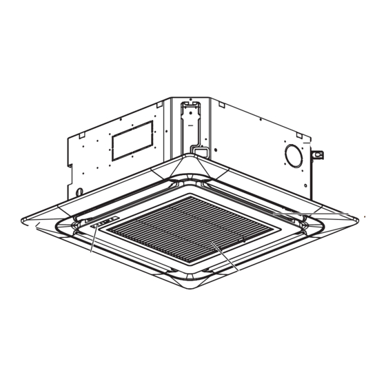
Installation [Ceiling Cassette Type] Ceiling dimension and hanging bolt location • The dimensions of the paper model for installation are the same as those of the ceiling opening dimensions. Ceiling Ceiling board Level gauge • Select and mark the position for fixing bolts and piping 585~660(23 1/16~26) (Ceiling Opening) hole. -
Page 30: Wiring Connection
Installation How to Fix Ceiling Keep the length of the bolt Hanging bolt from the bracket to 40mm(1-9/16 inch) (W3/8 or M10) Flat washer for M10 Air Conditioner body (W3/8 or M10) (accessory) Ceiling board Ceiling board Spring washer (M10) Keep the length of 31~34mm(1.22~1.34inch) between the air conditioner bottom surfac e and the ceiling surface... -
Page 31: Installation Of Wired Remote Controller(Optional)
Installation Installation of Wired Remote Controller(Optional) 1. Please fix tightly using provided screw after placing remote controller setup board on the place where you like to setup. - Please set it up not to bend because poor setup could take place if setup board bends. Please set up remote controller board fit to the reclamation box if there is a reclamation box. -
Page 32
Installation 3. Please fix remote controller upper part into
the setup board attached to the surface of the wall, as the picture below, and then, connect with setup board by pressing lower part. Wall Wall - Please connect not to make a gap at the remote controller Side Side and setup boardʼs upper and lower, right and left part. -
Page 33: Installation Of Decorative Panel
Installation Installation of Decorative Panel The decorative panel has its installation direction. Before installing the decorative panel, always remove the paper template. 1. Remove the packing and take out air inlet grille from front panel. Front grille 2. Remove the Corner covers of the panel. Coner cover 3. - Page 34 Installation 5. Fit the corner covers. 6. Open two screws of control panel cover. Screw 7. Connect one display connector and two vane control connectors of front panel to indoor unit PCB. The position marking on PCB is as: Display connector : CN-DISPLAY Vane control connector: CN-VANE 1,2 CN-VANE 1,2 CN-DISPLAY 8.
-
Page 35: Drain Piping
Installation CAUTION: Install certainly the decorative panel. Cool air leakage causes sweating. ⇨ Water drops fall. Good example Bad example Air conditioner unit Air conditioner Cool air leakage unit (no good) Ceiling Ceiling board board Decorative Decorative panel panel Fit the insulator (this part) and be careful for cool air leakage HEAT INSULATION 1. - Page 36 Installation [Ceiling Concealed Duct/Ceiling Cassette Type] • Drain piping must have down-slope (1/50 to 1/100): be Upward sure not to provide up-and-down slope to prevent rever- Pipe clamp routing sal flow. not allowed • During drain piping connection, be careful not to exert Indoor unit extra force on the drain port on the indoor unit.
- Page 37 Installation Attention 1. Possible drain-head height is up to 700mm(27 9/16 inch). So, it must be in- stalled below 700mm(27 9/16 inch). 1/50~1/100 MAX 700mm 2. Keep the drain hose downward up to (27 9/16 inch) 1/50~1/100 inclination. Prevent any upward flow or reverse flow in any part.
-
Page 38: Flaring Work And Connection Of Piping
Flaring Work and Connection of Piping Flaring Work and Connection of Piping Flaring work Main cause of gas leakage is defect in flaring work. Carry out correct flaring work in the fol- Copper Slanted Uneven Rough lowing procedure. tube 1) Cut the pipes and the cable. n Use the accessory piping kit or the pipes purchased locally. -
Page 39: Connection Of Piping - Outdoor
Flaring Work and Connection of Piping Connection of piping - Outdoor Align the center of the piping and sufficiently tighten the flare nut by hand. Connecting pipe order 1) A~D-UNIT gas side pipe 2) A~D-UNIT liquid side pipe (Only Indoor Units 18 kBtu/h class ) Finally, tighten the flare nut with torque wrench Outdoor unit(36 kBtu/h class) - Page 40 Flaring Work and Connection of Piping • For the units with capacity more than 48 kBtu/h, the installation piping is connectable in four Continuous directions.(refer to figure 1) • When connecting in a downward direction, knock out the knockout hole of the base pan. Torque wrench (refer to figure 2)
- Page 41 Flaring Work and Connection of Piping Branch [unit:mm] Model Gas Pipe Liquid Pipe Ø19.05 Ø9.52 Ø19.05 Ø9.52 PMBL5620 Ø9.52 Ø19.05 Y branch To Outdoor Unit To BD Unit • Ensure that the branch pipes are attached horizontally or vertically (see the diagram below.) Horizontal Facing upwards...
-
Page 42: Installation
Flaring Work and Connection of Piping Installation • This unit may be installed suspended from the ceiling or mounted on the wall. • This unit may only be installed horizontally , as shown in the diagram below.(Side B is facing up) However, it may be freely installed in any direction forward or back, and to the sides. -
Page 43: Installation Of The Main Unit
Flaring Work and Connection of Piping Installation of The Main Unit NOTICE • This unit has two different installation types: (1) Ceiling-suspended type and (2) wall-mounted type. • Choose the proper installation pattern according to the location of installation. • The installation location for printed wiring board can be changed. -
Page 44: Connecting The Cable Between Indoor Unit, Distributor Unit And Outdoor Unit
Connecting the Cable between Indoor Unit, Distributor Unit and Outdoor Unit Connecting the Cable between Indoor Unit, Distributor Unit and Outdoor Unit Connect the cable to the Indoor unit. Connect the cable to the indoor unit by connecting the wires to the terminals on the control board individually according to the outdoor unit connection. -
Page 45: Connect The Cable To The Distributor Unit
Connecting the Cable between Indoor Unit, Distributor Unit and Outdoor Unit Connect the cable to the Distributor unit. • Connect refrigerant pipes and connection wires to the appropriate ports maked with matching alphabets (A, B and C) on this unit. •... -
Page 46: Connect The Cable To The Outdoor Unit
Connecting the Cable between Indoor Unit, Distributor Unit and Outdoor Unit Connect the cable to the Outdoor unit. 1. Remove the control cover from the unit by loos- Outdoor unit ening the screw. Cover control Connect the wires to the terminals on the control board individually as the following. - Page 47 Connecting the Cable between Indoor Unit, Distributor Unit and Outdoor Unit NOTICE 1. Use connection cable NRTL(UL, ETL, CAS…) listed and stranded copper(4) THHN conductors, sunlight (UV) resistant ROHS compliant PVC jacket 600V direct burial listed, approved for wet conditions. Temperature rated for –20℃(-4℉) to 90℃(194℉). And this cable should be enclosed in conduit.
-
Page 48: Connection Method Of The Connecting Cable(Example)
Connecting the Cable between Indoor Unit, Distributor Unit and Outdoor Unit Connection method of the connecting cable(Example) (1) Remove the side panel and knockouts of conduit panel. (for low voltage line) (2) Pull out connection cable through conduit. (3) After conduit to the panel, fix nut to the opposite Cord clamp side of panel. -
Page 49: Checking The Drainage, Insulating The Pipe And Special Piping Applications
Checking the Drainage, Insulating the Pipe and Special Piping Applications Checking the Drainage, Insulating the Pipe and Special Piping Applications Checking the drainage 1. Remove the Air Filter. 2. Check the drainage. • Spray one or two glasses of water upon the evaporator. -
Page 50: Long Pipe Setting
Long Pipe Setting Long Pipe Setting 1. Open the top cover of outdoor unit. 2. Select one of the two selectable modes as follows. 3. Set the Zone as shown in Fig. 4. Close the top cover and check whether the product works normally. WARNING: Do not open the top cover or Set the pipe length when operat- ing the product. -
Page 51: Air Purging And Evacuation
Air Purging and Evacuation Air Purging and Evacuation Air and moisture remaining in the refrigerant system have undesirable effects as indicated below. 1. Pressure in the system rises. 2. Operating current rises. 3. Cooling(or heating) efficiency drops. 4. Moisture in the refrigerant circuit may freeze and block capillary tubing. 5. -
Page 52: Evacuation
Air Purging and Evacuation Evacuation 1. Connect the charge hose end described in the preceding steps to the vacuum pump to evacuate the tubing and indoor unit. Indoor unit Confirm the "Lo" knob of the manifold valve is open. Then, run the vacuum pump. The operation time for evacuation varies with tubing length and capacity of the pump. -
Page 53: Charging
Charging Charging n If installed total piping length is more than standard total length, additional refrigerant charging is necessary. Below standard total piping length, additional refrigerant charging is not required. Multiple Piping Models Unit:m(ft) Standard Total Piping Max total length of all Additional Refrigerant Outdoor Unit Ca- Max length of each... - Page 54 Charging Distributor type Models Additional charge (oz) = (( Total Main piping Length - Main Standard Length ) x 0.55 + (A Room Branch Length – Standard Length ) x 0.22 + (B Room Branch Length – Standard Length ) x 0.22 + (C Room Branch Length –...
-
Page 55: Combination Indoor Units
Combination indoor units Combination indoor units The indoor units connectable to the outdoor unit are shown below Indoor Unit Capacity (Btu/h class) Outdoor Unit Capacity (Btu/h class) Chassis Type 18 k 24 k 36 k 54 k Name Model Name Connectable Combination AMNW09GDEL1 AMNW12GDEL1... - Page 56 56 Multi Air Conditioner...
- Page 57 1. Please call the installing contractor of your product, as warranty service will be provided by them. 2. If you have service issues that have not been addressed by the contractor, please call 1-888-865-3026. CANADA Service call Number # : (888) LG Canada, (888) 542-2623...