Dell Latitude 3340 Owner's Manual
P47g
Hide thumbs
Also See for Latitude 3340:
- Owner's manual (51 pages) ,
- Setup and specifications (29 pages) ,
- Service manual (79 pages)
Table of Contents
Quick Links
Table of Contents

Related Manuals for Dell Latitude 3340


Summary of Contents for Dell Latitude 3340
- Page 1 Dell Latitude 3340 Owner's Manual Regulatory Model: P47G Regulatory Type: P47G001...
- Page 2 WARNING: A WARNING indicates a potential for property damage, personal injury, or death. Copyright © 2014 Dell Inc. All rights reserved. This product is protected by U.S. and international copyright and intellectual property laws. Dell and the Dell logo are trademarks of Dell Inc.
-
Page 3: Table Of Contents
Contents 1 Working on Your Computer................... 5 ....................5 Before Working Inside Your Computer ........................7 Turning Off Your Computer ....................7 After Working Inside Your Computer 2 Removing and Installing Components..............9 ..........................9 Recommended Tools ........................... 9 System Overview ..........................12 Removing the Battery ..........................12 Installing the Battery ............... - Page 4 Assigning a System Password and Setup Password ..........46 Deleting or Changing an Existing System and/or Setup Password 4 Diagnostics.......................47 ............47 Enhanced Pre-Boot System Assessment (ePSA) Diagnostics ..........................48 Device Status Lights ........................... 48 Battery Status Lights 5 Technical Specifications..................49 6 Contacting Dell....................... 55...
-
Page 5: Working On Your Computer
Damage due to servicing that is not authorized by Dell is not covered by your warranty. Read and follow the safety instructions that came with the product. - Page 6 If the computer is connected to a docking device (docked) such as the optional Media Base or Battery Slice, undock it. CAUTION: To disconnect a network cable, first unplug the cable from your computer and then unplug the cable from the network device. Disconnect all network cables from the computer.
-
Page 7: Turning Off Your Computer
CAUTION: To avoid damage to the computer, use only the battery designed for this particular Dell computer. Do not use batteries designed for other Dell computers. Connect any external devices, such as a port replicator, battery slice, or media base, and replace any cards, such as an ExpressCard. - Page 8 Turn on your computer.
-
Page 9: Removing And Installing Components
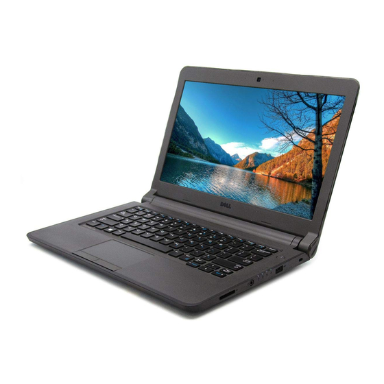
Removing and Installing Components This section provides detailed information on how to remove or install the components from your computer. Recommended Tools The procedures in this document may require the following tools: • Small flat-blade screwdriver • #0 Phillips screwdriver •... - Page 10 Figure 2. Features microphone camera camera-status light security cable slot power button USB 3.0 connector status lights audio connector memory card reader 10. touchpad 11. speakers 12. network-status light 13. USB 3.0 connector with PowerShare...
- Page 11 14. mini DisplayPort connector 15. HDMI connector 16. air vents 17. network connector 18. power connector Figure 3. Inside view — Back power connector system fan heatsink speaker memory module hard drive audio-connector board WLAN card system board coin-cell battery...
-
Page 12: Removing The Battery
Removing the Battery Follow the procedures in Before Working On Your Computer. Slide the release latches to unlock position and pull the battery to remove from the computer. Installing the Battery Insert the battery into its slot until the battery clicks into place. Follow the procedures in After Working Inside Your Computer. -
Page 13: Installing The Sim Card
Press in to release the SIM card and pull the SIM card out to remove from the computer. Installing the SIM Card Insert the SIM card into its slot on the computer and press till it clicks in place. Install the battery. Follow the procedures in After Working Inside Your Computer. -
Page 14: Installing The Base Cover
Perform the following steps to remove the base cover from the computer: a) Remove the screws that secure the base cover to the computer. b) Pry the edges of the base cover and remove the base cover from the computer. Installing the Base Cover Align the edges of the base cover on the computer and press it on the computer until it snaps in place. -
Page 15: Installing The Memory
Installing the Memory Insert the memory module into the memory socket and press until the memory module click in to place. Install the: a) base cover b) battery Follow the procedures in After Working Inside Your Computer. Removing the Keyboard Trim Follow the procedures in Before Working Inside Your Computer. -
Page 16: Installing The Keyboard Trim
Remove the keyboard trim from the computer. Installing the Keyboard Trim Align the keyboard trim to its place. Press along the sides of the keyboard trim until it snaps in place. Follow the procedures in After Working Inside Your Computer. NOTE: You may also need to press the center of the keyboard trim to install the keyboard trim in its place. - Page 17 Remove the screws that secure the keyboard to the computer. Slide and lift the keyboard from the computer to access the keyboard cable.
-
Page 18: Installing The Keyboard
Flip over the keyboard, disconnect the keyboard cable from its connector, and remove the keyboard from the computer. Installing the Keyboard Connect the keyboard cable to its connector on the computer. Install the keyboard in its place. Tighten the screws to secure the keyboard to the computer. Install the: a) keyboard trim b) battery... -
Page 19: Installing The Coin-Cell Battery
Perform the following steps to remove the coin-cell battery from the computer: a) Disconnect the coin-cell battery cable from the system board. b) Pull the coin-cell battery to detach the adhesive underneath which attaches it to the computer. c) Remove the coin-cell battery from the computer. Installing the Coin-Cell Battery Connect the coin-cell battery cable to the system board. -
Page 20: Installing The Audio-Connector Board
Perform the following steps to remove the audio-connector board from the computer: a) Disconnect the audio-connector board cable from the system board. b) Remove the screw that secures the audio-connector board to the computer. c) Lift and remove the audio-connector board from the computer. Installing the Audio-Connector Board Place the audio-connector board in its slot on the computer. -
Page 21: Installing The Hard Drive
Perform the following steps to remove the hard drive from the computer: a) Remove the screws that secure the hard drive to the computer. Slide the hard drive to disconnect from its connector on the system board. b) Lift and remove the hard drive from the computer. Installing the Hard Drive Align the hard drive on its bay on the computer. -
Page 22: Installing The Speakers
Disconnect the speaker cable from the system board [1]. Un-route the speaker cable from its channels on the computer [2]. Dislodge the speaker tabs from the holders on the computer [1]. Lift and remove the speakers from the computer [2]. Installing the Speakers Place the speakers in its compartments and route the cable through the channels. -
Page 23: Removing The Wireless Local Area Network (Wlan) Card
Install the: a) base cover b) battery Follow the procedures in After Working Inside Your Computer. Removing the Wireless Local Area Network (WLAN) Card Follow the procedures in Before Working on Your Computer. Remove the: a) battery b) base cover Remove the adhesive tape that secures the antenna cables to the WLAN card. -
Page 24: Removing The Wireless Wide Area Network (Wwan) Card
Install the: a) base cover b) battery Follow the procedures in After Working Inside Your Computer. Removing the Wireless Wide Area Network (WWAN) Card Follow the procedures in Before Working on Your Computer. Remove the: a) battery b) base cover Remove the adhesive tape that prevents the antenna cables to the WWAN card. -
Page 25: Removing The System Fan
Install the: a) base cover b) battery Follow the procedures in After Working Inside Your Computer. Removing the System Fan Follow the procedures in Before Working Inside Your Computer. Remove the: a) base cover b) battery... - Page 26 Perform the following steps to remove the system fan: a) Disconnect the system-fan cable [1] and power cable [2] from the system board. b) Un-route the power cable from its holder to access the system fan screw [3]. c) Remove the screws that secure the system fan to the computer. Lift the system fan away from the computer.
-
Page 27: Installing The System Fan
Installing the System Fan Perform the following steps to install the system fan: a) Place the system fan in its slot in the computer. b) Connect the system-fan cable and power cable to the system board. c) Tighten the screws to secure the system fan to the computer. d) Route the power cable to its holder in the computer. -
Page 28: Installing The Heatsink
Loosen the captive screws that secure the heatsink to the computer and remove the heatsink from the computer. Installing the Heatsink Place the heatsink on the computer. Tighten the captive screws to secure the heatsink to the system board. Route the WLAN antenna cables along their channels on the system board. Install the: a) system fan b) base cover... - Page 29 Perform the following steps: a) Disconnect the antenna cables from WLAN card. Un-route the antenna cables from the WLAN card . b) Remove the screw that secures the bracket over the display cable and remove the bracket . c) Disconnect the display cable from the system board. Perform the following steps: a) Disconnect the touch panel, network connector, and display cables: b) Remove the screws that secure the display hinges to the palmrest assembly.
-
Page 30: Installing The Display Assembly
Slide the palmrest assembly away to release the display assembly. Installing the Display Assembly Align the palmrest assembly on the display assembly. Tighten the screws to secure the display hinges to the palmrest assembly. Connect the following cables: a) touch panel b) network connector c) display Align the bracket over the display cable and tighten the screw to secure the bracket to the computer. -
Page 31: Removing The System Board
Removing the System Board Follow the procedures in Before Working on Your Computer. Remove the: a) battery b) SIM card c) base cover d) memory e) keyboard trim f) keyboard g) coin-cell battery h) audio-connector board hard drive WLAN card k) WWAN l) system fan m) heatsink... -
Page 32: Installing The System Board
Remove the screws that secure the system board to the chassis. Lift and remove the system board from the chassis. Installing the System Board Replace the system board on the chassis. Tighten the screws to secure the system board to the chassis. - Page 33 Connect the following cables to their connectors on the system board: a) power b) display-cable bracket and display c) network connector d) touch panel e) speaker f) audio connector g) touchpad Install the: a) heatsink b) system fan c) WWAN card d) WLAN card e) hard drive f) audio-connector board...
-
Page 35: System Setup
Boot Sequence allows you to bypass the System Setup‐defined boot device order and boot directly to a specific device (for example: optical drive or hard drive). During the Power-on Self Test (POST), when the Dell logo appears, you can: •... -
Page 36: System Setup Options
Table 1. Navigation Keys Keys Navigation Up arrow Moves to the previous field. Down arrow Moves to the next field.Allows you to select a value in the selected field (if applicable) or follow the link in the field. Spacebar Expands or collapses a drop‐down list, if applicable. - Page 37 Option Description Date/Time Allows you to set the date and time. Table 3. System Configuration Option Description Integrated NIC Allows you to configure the integrated network controller. The options are: • Disabled • Enabled • Enabled w/PXE (Default Setting) SATA Operation Allows you to configure the internal SATA hard-drive controller.
- Page 38 Option Description Audio Allows you to enable or disable the integrated audio controller. • Enable Audio (Default Setting) Unobtrusive Mode When enabled, pressing Fn + B will turn off all light and sound emissions in the system. Press Fn + B to resume normal operation.
- Page 39 Option Description Default Setting: Enable Strong Password is not selected. Password Configuration You can define the length of your password. Min = 4 , Max = 32 Password Bypass Allows you to enable or disable the permission to bypass the System and the Internal HDD password, when they are set.
- Page 40 Option Description Mode option is disabled by default. The options are: • • • • If you enable the Custom Mode, the relevant options for PK, KEK, db, and dbx appear. The options are: • Save to File- Saves the key to a user- selected file •...
- Page 41 Option Description Intel TurboBoost This option allows you to enable or disable the Intel TurboBoost mode of the processor. Default Setting: Enable Intel TurboBoost Hyper-Thread Control Allows you to enable or disable the HyperThreading in the processor. Default Setting: Enabled Rapid Start Technology This option allows you to enable or disable the Intel Rapid Start feature...
- Page 42 Option Description • Disabled - Does not allow the system to power on by special LAN signals when it receives a wake-up signal from the LAN or wireless LAN. (Default Setting) • LAN Only - Allows the system to be powered on by special LAN signals. •...
-
Page 43
Option Description Fn Key Emulation Allows you to match the
key feature of PS-2 keyboard with the key feature in an internal keyboard. The option is enabled by default. • Enable Fn Key Emulation Fn Lock Options This option when enabled allows the hot key combination ... -
Page 44: Updating The Bios
It is recommended to update your BIOS (system setup), on replacing the system board or if an update is available. For laptops, ensure that your computer battery is fully charged and connected to a power outlet Re-start the computer. Go to dell.com/support. -
Page 45: System And Setup Password
Enter the Service Tag or Express Service Code and click Submit. NOTE: To locate the Service Tag, click Where is my Service Tag? NOTE: If you cannot find your Service Tag, click Detect My Product. Proceed with the instructions on screen. If you are unable to locate or find the Service Tag, click the Product Category of your computer. -
Page 46: Deleting Or Changing An Existing System And/Or Setup Password
To enter a system setup, pressimmediately after a power-on or re-boot. In the System BIOS or System Setup screen, select System Security and press . The System Security screen appears. In the System Security screen, verify that Password Status is Unlocked. Select System Password , enter your system password, and press ... -
Page 47: Diagnostics
Diagnostics If you experience a problem with your computer, run the ePSA diagnostics before contacting Dell for technical assistance. The purpose of running diagnostics is to test your computer's hardware without requiring additional equipment or risking data loss. If you are unable to fix the problem yourself, service and support personnel can use the diagnostics results to help you solve the problem. -
Page 48: Device Status Lights
Turns on when wireless networking is enabled. Battery Status Lights If the computer is connected to an electrical outlet, the battery light operates as follows: Alternately An unauthenticated or unsupported non-Dell AC adapter is attached to your blinking amber laptop. light and white... -
Page 49: Technical Specifications
Technical Specifications NOTE: Offerings may vary by region. The following specifications are only those required by law to ship with your computer. For more information about the configuration of your computer, go to Help and Support in your Windows operating system and select the option to view information about your computer. - Page 50 Audio External Microphone-in/stereo headphones combo connector Speakers Two (2W per channel) Internal speaker amplifier Two (2W per channel) Volume controls Software program menus, media controls, and keyboard function keys Communications Network adapter 10/100/1000 Mbps Ethernet LAN Wireless • Internal wireless local area network (WLAN), Bluetooth •...
- Page 51 Display Z-height Front • 22.70 mm (0.89 inch) - Non-Touch • 24.40 mm (0.96 inch) - Touch Back • 22.70 mm (0.89 inch) - Non-Touch • 25.60 mm (1.01 inch) - Touch Weight (with 4-cell battery) 3.69 lb (1.67 kg) – Non-Touch Maximum resolution 1366 x 768 pixels at 262 K colors Maximum Brightness...
- Page 52 Battery 4-cell and 6-cell 49.15 mm (1.94 inches) Weight: 4-cell 259.00 g (0.57 lb) 6-cell 364.00 g (0.80 lb) Voltage: 4-cell 7.40 V 6-cell 11.10 V Approximate charge time for a 4–cell and 6– • 4 cell – 6 hours cell battery with computer off •...
- Page 53 Environmental Temperature range: Operating 0 °C to 35 °C (32 °F to 95 °F) Storage -40 °C to 65 °C (–40 °F to 149 °F) Relative humidity (maximum): Operating 10 % to 90 % (noncondensing) Storage 5 % to 95 % (noncondensing) Altitude (maximum): –15.2 m to 3048 m (–50 to 10,000 ft) Operating...
-
Page 55: Contacting Dell
Dell product catalog. Dell provides several online and telephone-based support and service options. Availability varies by country and product, and some services may not be available in your area. To contact Dell for sales, technical support, or customer service issues: Visit dell.com/support...