Table of Contents
Table of Contents

Related Manuals for D-Link EasySmart DES-1100-16


Summary of Contents for D-Link EasySmart DES-1100-16
- Page 1 Ver. 1.02...
-
Page 2: Table Of Contents
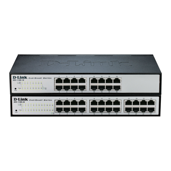
D-Link Web Smart Switch User Manual Table of Contents Table of Contents ............................. i About This Guide............................. 1 Terms/Usage..............................1 Copyright and Trademarks ..........................1 Product Introduction ............................2 DES-1100-16 ..............................2 Front Panel ..............................2 Rear Panel..............................2 DES-1100-24 ..............................2 Front Panel .............................. - Page 3 D-Link Web Smart Switch User Manual System > System Settings ........................22 System > Port Settings..........................23 System > Trap Settings For SmartConsole....................23 System > Password Access Control ......................24 L2 Features > Port Trunking........................24 L2 Features > IGMP Snooping......................... 24 L2 Features >...
-
Page 4: About This Guide
Reproduction in any manner whatsoever without the written permission of D-Link Corporation is strictly forbidden. Trademarks used in this text: D-Link and the D-LINK logo are trademarks of D-Link Corporation; Microsoft and Windows are registered trademarks of Microsoft Corporation. Other trademarks and trade names may be used in this document to refer to either the entities claiming the marks and names or their products. -
Page 5: Product Introduction
D-Link Web Smart Switch User Manual Product Introduction Thank you and congratulations on your purchase of D-Link EasySmart Switch Products. D-Link's next generation EasySmart Ethernet switch series blends plug-and-play simplicity with exceptional value and reliability for small and medium-sized business (SMB) networking. All models are housed in a new style rack-mount metal case with easy-to-view front panel diagnostic LEDs. -
Page 6: Rear Panel
D-Link Web Smart Switch User Manual Power LED: The Power LED lights up when the Switch is connected to a power source. Link/Act/Speed LED (Ports 1-24): Flashing: Indicates a network link through the corresponding port. Blinking: Indicates that the Switch is either sending or receiving data to the port. -
Page 7: Hardware Installation
D-Link Web Smart Switch User Manual Hardware Installation This chapter provides unpacking and installation information for the D-Link EasySmart Switch. Step 1: Unpacking Open the shipping carton and carefully unpack its contents. Please consult the packing list located in the User Manual to make sure all items are present and undamaged. - Page 8 D-Link Web Smart Switch User Manual Figure 6 – Attach the mounting brackets to the Switch Then, use the screws provided with the equipment rack to mount the switch in the rack. Figure 7 – Mount the Switch in the rack or chassis...
-
Page 9: Step 3 - Plugging In The Ac Power Cord
D-Link Web Smart Switch User Manual Step 3 – Plugging in the AC Power Cord Users may now connect the AC power cord into the rear of the switch and to an electrical outlet (preferably one that is grounded and surge protected). -
Page 10: Getting Started
This chapter introduces the management interface of D-Link EasySmart Switch. Management Options The D-Link EasySmart Switch can be managed through any port on the device by using the Web-based Management or through any PC using the SmartConsole Utility. Each switch must be assigned its own IP Address, which is used for communication with Web-Based Management. -
Page 11: Login Web-Based Management
Figure 12 – Logon Dialog Box SmartConsole Utility The SmartConsole Utility included in the installation CD is a program for discovering D-Link Smart Switches and EasySmart Switches within the same L2 network segment connected to your PC. This tool is only for computers running Windows 2000, Windows XP, or Windows Vista x64/86 operating systems. - Page 12 CD-Rom or DVD-Rom) and click OK. Follow the on-screen instructions to install the utility. Upon c ompletion, go to Start > Programs > D-Link SmartConsole Utility and open the SmartConsole Utility. Connect the Smart Switch to the sam e L2 network segment of your PC and use the SmartConsole Utility to discover the Smart Switches.
-
Page 13: Smartconsole Utility
D-Link Web Smart Switch User Manual SmartConsole Utility The D-Link SmartConsole Utility allows the administrator to quickly discover all D-Link Smart Switches and EasySmart Switches which are in the same domain of the PC, collect traps and log messages, and quick access to basic configurations of the switch. -
Page 14: Log
D-Link Web Smart Switch User Manual NOTE: If the Group Interval is set to 0, IGMP Snooping must be disabled in the Switch or the switches will not be discovered. Click this icon to launch the Log window. Click View Log to show the events of the SmartConsole Utility and the device. -
Page 15: File
D-Link Web Smart Switch User Manual File By clicking on this icon you will see below options: Figure 17 – SmartConsole File Monitor Save: Records the setting of the Device List as default for the next time the SmartConsole Utility is used. -
Page 16: Device Configuration
D-Link Web Smart Switch User Manual Device Configuration The Device Configuration in the SmartConsole Utility has five icons: Device Settings Device Password Manager Multi Firmware Upgrade DHCP Refresh Web Access and the device buttons for the Device List. Device Settings Select a switch from the Device List. - Page 17 D-Link Web Smart Switch User Manual...
-
Page 18: Add(+), Delete(-) And Discover The Device
D-Link Web Smart Switch User Manual Device Password Manager Select a switch from the Device List. Click on this icon to launch the Device Password Manager window. Here you can enter a new password and confirm it. Figure 20 – SmartConsole Device Password Manager Multi Firmware Upgrade The EasySmart switches’... -
Page 19: Device List
D-Link Web Smart Switch User Manual Figure 23 – SmartConsole Add device Figure 24 – SmartConsole Delete device Device List This list displays all discovered Web Smart and EasySmart switches on the network. Figure 25 – SmartConsole Device List Definitions of the Device List features: Monitor: Check the Monitor box and the SmartConsole will collect the trap and log data from the device. - Page 20 D-Link Web Smart Switch User Manual Gateway: Displays the Gateway setting of the device. Device Group Interval: Displays the intervals (in seconds). This feature is not available for EasySmart switches. Firmware version: Displays the current Firmware version of this device.
-
Page 21: Configuration
Logout button, it will be seen as an abnormal exit and the login session will still be occupied. Finally, by clicking on the D-Link logo at the upper-left corner of the screen you will be redirected to the local D-Link website. -
Page 22: Tool Bar > Save Menu
D-Link Web Smart Switch User Manual Tool Bar > Save Menu The Save Menu provides Save Configuration. Figure 27 – Save Menu Save Configuration Select to save the entire configuration changes you have made to the device to switch’s non-volatile RAM. -
Page 23: Configuration Backup & Restore
D-Link Web Smart Switch User Manual Figure 32 – Tool Menu > Firmware upgrade Click Browse to browse your inventories for a saved firmware file. And then click Upgrade to restore the selected firmware file. CAUTION: Do not disconnect the PC or remove the power cord from device until upgrade is complete. -
Page 24: Function Tree
D-Link Web Smart Switch User Manual Function Tree All configuration options on the switch are accessed through the Setup menu on the left side of the screen. Click on the setup item that you want to configure. The following sections provide more detailed description of each feature and function. -
Page 25: System > System Settings
D-Link Web Smart Switch User Manual Figure 35 – Device Information System > System Settings The System Setting allows the user to configure the IP address and the basic system information of the Switch. IP Information: There are two ways for the switch to obtain an IP address: Static and DHCP (Dynamic Host Configuration Protocol). -
Page 26: System > Port Settings
D-Link Web Smart Switch User Manual System > Port Settings In the Port Setting page, the status of all ports can be monitored and adjusted for optimum configuration. By selecting a range of ports (From Port and To Port), the Speed can be set for all selected ports, effective by clicking Apply. -
Page 27: System > Password Access Control
D-Link Web Smart Switch User Manual Select the event message(s) to be sent out to the managing station. System Event: The system level messages contain: Device Bootup - System boot-up information Illegal Login - Events of incorrect password logins and records the IP of the source PC... -
Page 28: L2 Features > Port Mirroring
D-Link Web Smart Switch User Manual If the IGMP server is not able to send out query control message automatically, a static router port may be required to be configured manually. Select the ports to be assigned as router ports for IGMP snooping in the IGMP Static Router Port List, and click Apply for changes to take effect. -
Page 29: L2 Features > Statistics
D-Link Web Smart Switch User Manual switches. The Switch will automatically shutdown the port and sends a log to the administrator. The Loopback Detection port will be unlocked when the Loopback Detection Recover Time times out. The Loopback Detection function can be implemented on a range of ports at a time. You may enable or disable this function using the pull-down menu. - Page 30 D-Link Web Smart Switch User Manual Figure 44 – L2 Features > Statistics menu Receive Packet & Transmit Packet: Number of packets received and transmitted successfully. Figure 45 – L2 Features > Statistics menu Transmit Packet & Collision: Number of transmit packets resulting in collision.
- Page 31 D-Link Web Smart Switch User Manual Figure 46 – L2 Features > Statistics menu Receive Packet & Drop Packet: Number of receive packets resulting in drop packets. Figure 47 – L2 Features > Statistics menu Receive Packet & CRC Packet: Number of receive packets resulting in CRC error.
-
Page 32: Vlan > 802.1Q Vlan
D-Link Web Smart Switch User Manual Figure 48 – L2 Features > Statistics menu Refresh All: Refreshes the details collected and displayed. Clear All Counters: Resets the details displayed. VLAN > 802.1Q VLAN A VLAN is a group of ports that can be anywhere in the network, but communicate as though they were in the same area. - Page 33 D-Link Web Smart Switch User Manual Figure 49 – VLAN > 802.1Q VLAN > Default Setting Figure 50 – VLAN > 802.1Q VLAN > Add VID Figure 51 – VLAN > 802.1Q VLAN > Assign PVID Rename: Click to rename the VLAN group.
-
Page 34: Vlan > 802.1Q Management Vlan
D-Link Web Smart Switch User Manual Figure 52 – VLAN > 802.1Q VLAN > VLAN Table NOTE: When 802.1Q VLAN is enabled, the Port- Based VLAN settings will be reset to default. NOTE: When 802.1Q VLAN is disabled, its settings will be cleaned, and Management VLAN will be disabled simultaneously. -
Page 35: Qos > 802.1P Default Priority
D-Link Web Smart Switch User Manual Add VLAN: Click to create a new VLAN name and to select VLAN ports. The VLAN name should be less than 10 characters. To save the members in a group, click Apply. Rename: Click to rename the VLAN group. -
Page 36: Qos > Bandwidth Control
D-Link Web Smart Switch User Manual Figure 56 – QoS > Storm Control Storm Control Type: User can select the different Storm type from Broadcast Only, Multicast & Broadcast, and Multicast & Broadcast & Unknown Unicast. Threshold (pps): If storm control is enabled (by default it is disabled), the threshold can be set from 0.8 to 12.6Kbits per second at 10Mbps speed, and 8 ~ 126Kbits per second at 100Mbps speed. -
Page 37: Security > Mac Address Table > Static Mac
D-Link Web Smart Switch User Manual From Port / To Port: A consecutive group of ports may be configured starting with the selected port. Type: This drop-down menu allows you to select between RX (receive), TX (transmit), and Both. This setting will determine whether the bandwidth ceiling is applied to receiving, transmitting, or both receiving and transmitting packets. - Page 38 D-Link Web Smart Switch User Manual Figure 59 – Security > Dynamic Forwarding Table...
-
Page 39: Appendix A - Ethernet Technology
D-Link Web Smart Switch User Manual Appendix A - Ethernet Technology This chapter will describe the features of the D-Link EasySmart Switch and provide some background information about Ethernet/Fast Ethernet/Gigabit Ethernet switching technology. Gigabit Ethernet Technology Gigabit Ethernet is an extension of IEEE 802.3 Ethernet utilizing the same packet structure, format, and support for CSMA/CD protocol, full duplex, and management objects, but with a tenfold increase in theoretical throughput of over 100-Mbps Fast Ethernet and a hundredfold increase over 10-Mbps Ethernet. -
Page 41: Appendix B - Technical Specifications
D-Link Web Smart Switch User Manual Appendix B - Technical Specifications Hardware Specifications QoS (Quality of Service) 802.1p priority, Key Components / Performance Up to 2 queues per port Switching Capacity: Bandwidth Control - DES-1100-16: 3.2Gbps Storm Control - DES-1100-24: 4.8Gbps Max. -
Page 42: Appendix C - Rack Mount Instructions
D-Link Web Smart Switch User Manual Appendix C – Rack mount Instructions Safety Instructions - Rack Mount Instructions - The following or similar rack-mount instructions are included with the installation instructions: A) Elevated Operating Ambient - If installed in a closed or multi-unit rack assembly, the operating ambient temperature of the rack environment may be greater than room ambient.