Table of Contents
Quick Links
MICRO HiFi COMPONENT SYSTEM
RXD-M31MD/
LS-M31 ( M )
SERVICE MANUAL
(HM-381MD)
620
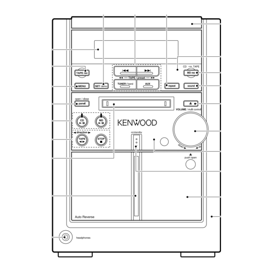
Display lens
(B12-0386-08)
675
Knob (TAPE REC)
(K29-7691-08)
676
Knob (MENU)
(K29-7692-08)
685
Knob (PANEL BUTTON)
(K29-7701-08)
682
Knob (MD/CD PLAY)
(K29-7698-08)
683
Knob (TAPE/STOP)
(K29-7699-08)
612
MD door
(A52-0376-08)
614
Cass door lens
(B10-3524-08)
JK602
Headphone jack
(E11-0398-08)
In compliance with Federal Regulations, following are repro-
ductions of labels on, or inside the product relating to laser
product safety.
678
679
Knob (FF/TUNER/AUX)
Knob
(K29-7695-08)
(SET DEMO)
(K29-7694-08)
Knob (REPEAT)
677
(K29-7693-08)
KENWOOD-Crop. certifies this equipment conforms to DHHS
Regulations No. 21 DFR 1040. 10, Chapter 1, Subchapter J.
DANGER : Laser radiation when open and interlock
defeated.
AVOID DIRECT EXPOSURE TO BEAM
© 1999-12/B51-5555-00 (K/K) 1853
* Refer to parts list on page 42.
Top panel
(A21-3801-08)
605
Tuning panel
(A21-3779-08)
680
Knob (MD REC)
(K29-7696-08)
681
Knob (SOUND)
(K29-7697-08)
686
Knob (MD EJECT)
(K29-7702-08)
674
Knob (VOLUME)
(K29-7690-08)
607
Control panel *
(A21-)
684
Knob (ON/STANDBY)
(K29-7700-08)
603
Cass door cover
(A02-2945-08)
Front cabinet
(A60-1745-08)
70%
Table of Contents

Related Manuals for Kenwood RXD-M31MD


Summary of Contents for Kenwood RXD-M31MD
- Page 1 * Refer to parts list on page 42. In compliance with Federal Regulations, following are repro- KENWOOD-Crop. certifies this equipment conforms to DHHS Regulations No. 21 DFR 1040. 10, Chapter 1, Subchapter J. ductions of labels on, or inside the product relating to laser product safety.
-
Page 2: Table Of Contents
(A70-1287-05) : RC-M0505E (E,T) Battery cover (A09-1114-08) System configuration SYSTEM MAIN UNIT SPEAKER HM-381MD RXD-M31MD LS-M31(M) Refer number for LS-M31(M), refer to parts list on page 52. Cautions Operation to reset Note related to transportation and movement The microcomputer may fall into malfunction (impossibil- Before transporting or moving this unit, carry out the follow- ity to operate, erroneous display, etc.) when the power... -
Page 3: External View
RXD-M31MD EXTERNAL VIEW HS cover (BLACK) ANTENNA (F07-1685-18) SPEAKERS Metal plate (6–16Ω) (LEFT SIDE) (A50-1332-08) Lock terminal board * 300W (E70-) Speaker terminal – (E70-0113-08) – Phono jack (E63-1092-08) DIGITAL SUPER OPTICAL WOOFER PRE OUT Oscillating module* Slide switch (OPTICAL) - Page 4 SERCH uPD78058GC-B20 DSCK IC502 MD-ST MD MECHA. RESET 5.0V DSTB TC74HCT7007AF PDOWN CONTROL u-COM MDDATA (LEVEL SHIFT) LOAD SW 3.3V DISPLAY BOARD BOARD BOARD CN502 DRIVER IC801 Q1001- IC1001 J1001 1007 MD MECHA. ROTARY MDM-98A REMOTE (A/D) ENCODER C0NTROL RXD-M31MD...
-
Page 5: Block Diagram
1. Initialization 1-4 Mechanism initialization 3. Destination list of TUNER (DSW4=50pin, DSW3=49pin, DSW2=48pin) U-COM Discrimination 1-4-1 CD mechanism Receiving frequency Channel 1-1 Setting of initial conditions Desti- Desti- DSW2 Band range space nation DSW4 DSW3 • If a mechanism error occurs, “C” is indicated on the While pressing the [SET] key, plug the AC power cord nation display. - Page 6 4-3 Pin description of main microprocessor Pin No. Name Description Pin No. Name Description PWX33 Control port of MD CE. SYSTEM IC(LC75396)/PLL IC(LC72131)CE ENC1 Rotary encoder input(vol.A). PLL DO PLL data input. ENC2 Rotary encoder input(vol.B). Tuner SD detector input. H: no tuned L: tuned LED5...
- Page 7 5. Composition (MD section) 5-2 Pin description of MD u-com : UPD78058GC-B20(MD control board, IC501) Pin No. Name Description 5-1 Microprocessor periphery block diagram PDOWN MDM-98A power down detector. SEARCH CD search output. (MAIN BOARD: IC401) LOAD IN Load switch input. •...
-
Page 8: Adjustment
(4) Basic operation in test mode. 6-3 Test mode of MD player The muting during mode selection is not controlled in the test mode. 6-3-1 Inspection mode The test mode is cancelled when the AC power is turned OFF. Setting : While pressing the [MD REC] Key, plug the AC power cord into an AC power outlet. (5) The operation of the keys in the test mode. -
Page 9: Wave Form
• Test Mode Step No. Setting Method Remarks Display Step 5 Continuous playback (groove section) 1. AUTO pre-adjustment mode • Automatic pre-adjustment is performed. (After adjustment the grating adjustment mode is set.) • The adjustment value is output with the aid of system controller interface. Step 6 Press the MD STOP button. - Page 10 6-4 Test mode of CD player 7. MD mechanism error message 6-4-1 Main unit DISPLAY DESCRIPTION (1) Setting of the test mode BLANK DISC Non Recorded disc While pressing the [CD PLAY] key, plug the AC CAN'T COPY Inhibit to record by SCMS power cord into an AC outlet.
-
Page 11: Pc Board
Adjustment of tuner Adjustment of cassette deck INPUT OUTPUT TUNER ALIGNMENT INPUT OUTPUT CASSETTE TAPE ALIGNMENT ITEM ALIGN FOR FIG. ITEM ALIGN FOR FIG. SETTING SETTING DECK SETTING POINTS SETTING SETTINGS SETTINGS POINTS Unless otherwise specified, set the respective switches as follows: 0dBs = 0.775V Adjust VR1 and stop TAPE : NORMAL... -
Page 12: Wave Form
RXD-M31MD WAVE FORM PLAY PIT PLAY Stopped Stopped NORM: 100M S/s NORM: 1M S/s 1997 / 08 / 04 09:30:15 1997 / 08 / 04 13:35:24 CH1 500mV 200mV 500ns/div 1ms/div AC 10:1 DC 10:1 DC 10:1 AC 10:1 DC 10:1... - Page 13 RXD-M31MD WAVE FORM PLAY Stopped Stopped NORM: 1k S/s NORM: 100M S/s 1997 / 08 / 04 14:19:52 1997 / 08 / 04 11:23:12 1s/div 2us/div DC 10:1 DC 10:1 DC 10:1 DC 10:1 DC 10:1 DC 10:1 DC 10:1...
-
Page 14: Schematic Diagram
PC BOARD (Component side view) MD MAIN PWB-A (TOP VIEW) Through hole. R1808 R1805 C1804 L1501 Q1805 L1300 R1514 IC1300 R1519 C1802 Q1500 R1532 C1704 C1501 Q1800 R1708 R1304 R1712 Q1400 C1408 Q1702 R1711 C1703 R1801 C1707 L1700 C1805 R1702 R1406 IC1701 C1702... - Page 15 PC BOARD (Component side view) MD MAIN PWB-A (BOTTOM VIEW) CNW2002 MAGNET HEAD(32) CW1903 RECORD TP1511 TP1411 TP1513 D1300 CN1501 TP1519 CN1300 C1803 TP1521 TP1506 TP1518 TP1522 R1513 Q1300 Q1301 TP1524 TP1515 Q1303 TP1301 TP1300 C1505 TP1516 TP1525 C1508 TP1606 TP1509 C1502 TP1517...
-
Page 16: Display Unit
PC BOARD (Component side view) MD CONTROL UNIT R554A R553A C534A C533A R564A R562A R561A C536A C535A R563A R566A R565A R545A R552A R567A R544A R568A C529A R550A C530A R535A R543A R542A R541A R528A C522A R539A R540A R533A R534A C515A KEY CONTROL UNIT Q1003 SW1007 SW1002... - Page 17 PC BOARD (Component side view) CASSETTE DECK UNIT POWER UNIT Refer to the schematic diagram for the value of resistors and capacitors.
-
Page 18: Main Unit
PC BOARD (Component side view) SPEAKERS SUPER WOOFER PRE OUT POWER UNIT PHONES POWER UNIT R642A R641A MAIN UNIT Refer to the schematic diagram for the value of resistors and capacitors. - Page 19 PC BOARD(Component side view) MAIN UNIT Refer to the schematic diagram for the value of resistors and capacitors.
-
Page 20: Parts List
MD MECHANISM (D40-1602- 5) MDM-98A IC1101 IR3R55 MECHA. (SW PWB) IC1201 LR376484 CN1901 C1400 IC1202 IX2474AF CW1901 R1902 LEAD IN IC1300 74ACT02F 0.022 1.8K LEAD IN IC1401 IX0253AW WRITE HINF HINF +4.8V +4.8V IC1402 S29294A SW1951-A IC1601 BA5984FP LOADING LOADING IC1701 UDA1344 R1901... - Page 21 R1811 SYSD2 R1409 SYSD3 INNER 3.9V R1807 3.2V 3.3V IC1801 C1619 330P 3.4V 4.8V +4.8V +3.2V +3.2V +3.2V +4.8V Q1403 Q1402 IC1402 E PROM 0.4V 3.2V Q1400 Q1401 3.2V 0.4V DATA +3.2V +3.2V PRTCT +3.2V +3.2V RXD-M31MD (1/5) RXD-M31MD Y39-3212-70...
- Page 22 MAIN BOARD JK301 R315A AUX IN PICKUP (KSS-213C) R316A FCS- TRK- TRACKING COIL TRK+ CN201 FOCUSING COIL FCS+ SLD+ R256A 10 4.4V -VPD R201A 68K C237 10u16 R320A 2.2K R324A 470 SHORT R202A 68K SLD- C238 10u16 R319A R323A 470 C206A C208A LAND...
- Page 23 MAIN BOARD +12V +12V R107 +12V +12V T103 T104 CF103 450kHz CF102 10.7MHz C158A 100P R108A 5.6K (E,T) TYPE C411A ONLY 0.01 R148A 5.6K 5.0V FM/AM 5.0V /MPX CODE4 Q103 SYSTEM (E,T) TYPE ONLY IC101 5.0V CODE3 PRTMD (BOTTOM VIEW) F.H/L CODE2 X102...
- Page 24 AM mode. MODULATION MODE CARRIER ANT INPUT FREQUENCY DEVIATION 98MHz 1kHz STEREO 67.5kHz 7.5kHz(Pilot) 60dB 1000(999)kHz 400Hz MONO 30% MOD 60dB DISPLAY BOARD -CN801 15 14 13 12 11 SW401 RXD-M31MD CN401 CN402 RXD-M31MD(E) (2/5) Y39-3212-70...
- Page 25 MDM-98 -CN1501 MD CONTROL BOARD IC503 CASSETTE BOARD R708A IC703 OPE.AMP MAIN R707A R705A BOARD 220K -CN405 IC702 C735A 47P R567A P.B/REC EQ. C705A R709A 0.01 R558A C529A NF/L 100K 820P R735A 22K R568A R711A IREF EQ/L C707 R703A 10K 2.2u50 B.IN/L C530A...
- Page 26 R642A (230V) D610 1.2K C649 (K,P) : AC120V 60Hz : AC110-120V/220-240V~ 0.01 50/60Hz -32.2V Q612 (E,T) : AC230V~ , 50Hz D607 D609 +12V +12V R649 C639 F604 3.3M R646 0.01 MOTOR 500mA 250V BOARD 1/2W -CN901 RXD-M31MD (3/5) RXD-M31MD Y39-3212-70...
- Page 27 RXD-M31MD EXPLODED VIEW (MD MECHANISM) BKx2 BKx2 CW1903 RHMD PUMD SW1956 PWB-B SW1953 1952 SW1954 SW1955 CW1901 BCx2 PWB-A BLx4 BCx2 M1.7x9.5 : N39-1795-45 M1.7x7.5 : N09-3426-08 M1.7x2 : N39-1720-45 M1.7x2.2 : N09-3115-08 M1.7x3 : N39-1730-45 M1.7x2.5 : N09-3347-08 FMMD LMMD M1.7x8.9...
- Page 29 ¿3x6 : N88-3006-46 WASHER : N15-1026-46 SW401 WASHER : N15-1030-46 FM 75‰ JK101 DIGITAL OUT OPTICAL JK302 AUX INPUT JK301 AC110- AC220- 120V~ 240V~ SW603 open/close panel SW1007 SW1002 SW1004 SW1003 VOLUME V1001 direction SW1001 SW1005 SW1006 IC1001 TAPE RXD-M31MD...
- Page 30 Ref. No Parts No. Description Ref. No Parts No. Description ress Parts nation marks marks ress Parts nation RXD-M31MD 1G,2G D39-0345-08 DAMPER SET 130-03313-010 J42-0343-08 POWER CORD BUSH 130-00000-001 A21-3800-08 PANEL COVER 109-03311-101 J42-0344-08 POWER CORD BUSH 130-00000-002 A02-2940-08 TOP CABINET...
- Page 31 New Parts New Parts Parts without Parts No. are not supplied. Parts without Parts No. are not supplied. Les articles non mentionnes dans le Parts No. ne sont pas fournis. Les articles non mentionnes dans le Parts No. ne sont pas fournis. Teile ohne Parts No.
- Page 32 New Parts New Parts Parts without Parts No. are not supplied. Parts without Parts No. are not supplied. Les articles non mentionnes dans le Parts No. ne sont pas fournis. Les articles non mentionnes dans le Parts No. ne sont pas fournis. Teile ohne Parts No.
- Page 33 New Parts New Parts Parts without Parts No. are not supplied. Parts without Parts No. are not supplied. Les articles non mentionnes dans le Parts No. ne sont pas fournis. Les articles non mentionnes dans le Parts No. ne sont pas fournis. Teile ohne Parts No.
- Page 34 New Parts New Parts Parts without Parts No. are not supplied. Parts without Parts No. are not supplied. Les articles non mentionnes dans le Parts No. ne sont pas fournis. Les articles non mentionnes dans le Parts No. ne sont pas fournis. Teile ohne Parts No.
- Page 35 New Parts New Parts Parts without Parts No. are not supplied. Parts without Parts No. are not supplied. Les articles non mentionnes dans le Parts No. ne sont pas fournis. Les articles non mentionnes dans le Parts No. ne sont pas fournis. Teile ohne Parts No.
- Page 36 New Parts New Parts Parts without Parts No. are not supplied. Parts without Parts No. are not supplied. Les articles non mentionnes dans le Parts No. ne sont pas fournis. Les articles non mentionnes dans le Parts No. ne sont pas fournis. Teile ohne Parts No.
- Page 37 New Parts New Parts Parts without Parts No. are not supplied. Parts without Parts No. are not supplied. Les articles non mentionnes dans le Parts No. ne sont pas fournis. Les articles non mentionnes dans le Parts No. ne sont pas fournis. Teile ohne Parts No.
- Page 38 New Parts New Parts Parts without Parts No. are not supplied. Parts without Parts No. are not supplied. & Les articles non mentionnes dans le Parts No. ne sont pas fournis. Les articles non mentionnes dans le Parts No. ne sont pas fournis. Teile ohne Parts No.
- Page 39 New Parts New Parts Parts without Parts No. are not supplied. Parts without Parts No. are not supplied. Les articles non mentionnes dans le Parts No. ne sont pas fournis. Les articles non mentionnes dans le Parts No. ne sont pas fournis. Teile ohne Parts No.
- Page 40 New Parts New Parts Parts without Parts No. are not supplied. Parts without Parts No. are not supplied. ¡ ™ Les articles non mentionnes dans le Parts No. ne sont pas fournis. Les articles non mentionnes dans le Parts No. ne sont pas fournis. Teile ohne Parts No.
-
Page 41: Specifications
Dimensions ..........W : 180 mm H : 257 mm D : 275 mm Weight (net) ............5.1 kg KENWOOD follows a policy of continuous advancements in development. For this reason specifications may be changed without notice. Notes Notes Notes... - Page 42 Av. Moema, 170-17˚, Andar-Cobertura “B”, Ed. Maximum Service Center, 04077-020 Moema, São Paulo-SP-Brasil KENWOOD ELECTRONICS U.K. LIMITED KENWOOD House, Dwight Road, Watford, Herts., WD1 8EB., United Kingdom KENWOOD ELECTRONICS BELGUM N.V. Meachelsesteenweg 418, B-1930 Zaventem, Belgium KENWOOD ELECTRONICS DEUTSCHLAND GMBH Rembrücker Str.