Honeywell ADEMCO VISTA-15PSIA Installation And Setup Manual
Ademco vista series
Hide thumbs
Also See for ADEMCO VISTA-15PSIA:
- User manual (64 pages) ,
- Programming manual (48 pages) ,
- Installation and operation manual (40 pages)

Related Manuals for Honeywell ADEMCO VISTA-15PSIA


Summary of Contents for Honeywell ADEMCO VISTA-15PSIA
- Page 1 ADEMCO VISTA SERIES VISTA-20P / VISTA-20PSIA VISTA-15P / VISTA-15PSIA Security Systems Installation and Setup Guide K5305-1V5 10/04 Rev. A...
-
Page 2: Recommendations For Proper Protection
RECOMMENDATIONS FOR PROPER PROTECTION The Following Recommendations for the Location of Fire and Burglary Detection Devices Help Provide Proper Coverage for the Protected Premises. Recommendations For Smoke And Heat Detectors With regard to the number and placement of smoke/heat detectors, we subscribe to the recommendations contained in the National Fire Protection Association's (NFPA) Standard #72 noted below. -
Page 3: Table Of Contents
Features and Installation Highlights...1-1 Capabilities and Functions...1-1 Compatible Devices ...1-2 Important Installation Highlights (Installer Please Read) ...1-2 Mounting and Wiring the Control ...2-1 Installing the Control Cabinet and PC Board ...2-1 Cabinet and Lock ...2-1 Mounting the PC Board Alone (no RF Receiver) ...2-1 Mounting Board with RF Receiver...2-1 AUXILIARY DEVICE CURRENT DRAW WORKSHEET AC Power, Battery, and Ground Connections ...2-3... - Page 4 Table Of Contents (continued) Data Field Programming ...4-1 About Data Field Programming...4-1 System Setup Fields ( ∗ 20 – ∗29) ...4-1 Zone Sounds & Timing (∗31–∗39) ...4-1 Dialer Programming ( ∗ 40 – ∗ 50) ...4-2 System Status Report Codes ...4-4 Miscellaneous System Fields ...4-5 Pager Programming Fields...4-7 Miscellaneous System Fields ...4-8...
-
Page 5: Features And Installation Highlights
(collectively referred to as VISTA-15P series) Features and procedures apply to all, except where differences are noted. SIA Installations: The VISTA-20PSIA and VISTA-15PSIA are certified SIA-compliant controls that meet SIA specifications for False Alarm Reduction. The other controls described in this manual are not certified as SIA compliant, but can be programmed for False Alarm Reduction. -
Page 6: Compatible Devices
Installation and Setup Guide Compatible Devices Device VISTA-20P Addressable Keypads Touch Screen (AUI) Devices 4219, 4229 Zone Up to 5 for Expander Modules up to 40 exp. zones 5800 Series Wireless Up to 40 RF zones Output relays and/or Up to 16 Powerline Carrier Devices (X-10 type) On-Board Triggers... -
Page 7: Mounting And Wiring The Control
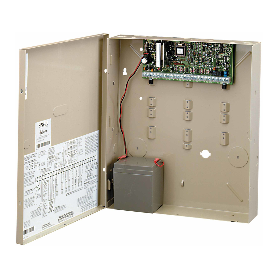
Mounting and Wiring the Control Installing the Control Cabinet and PC Board Cabinet and Lock 1. Mount the control cabinet to a sturdy wall in a clean, dry area, which is not readily accessible to the general public, using fasteners or anchors (not supplied) with the four cabinet mounting holes. -
Page 8: Auxiliary Device Current Draw Worksheet
Installation and Setup Guide CABINET RECEIVER CIRCUIT BOARD INSTALLATION WITH RECEIVER CIRCUIT BOARD WHITE MOUNTING CLIP NOTE A COMBINATION OF THESE MOUNTING CLIPS HAS BEEN INCLUDED IN YOUR INSTALLATION KIT. USE THE APPROPRIATE CLIPS FOR MOUNTING. IF NO RF RECEIVER IS USED, MOUNT THE PC BOARD USING EITHER THE WHITE OR BLACK CLIPS, WHICHEVER ARE INCLUDED IN THE CONTROL PANEL'S HARDWARE KIT. -
Page 9: Ac Power, Battery, And Ground Connections
AC Power, Battery, and Ground Connections 1321 Transformer Connect the 1321 Transformer (1321CN in Canada) to terminals 1 and 2 on the control board. See Wire Run Chart for wire size to use. • Use caution when wiring the transformer to the control to guard against blowing the transformer fuse (the fuse is non-replaceable). -
Page 10: Sounder (Bell) Connections
Installation and Setup Guide Sounder (Bell) Connections Basic Connections Make sounder connections to alarm output terminals 3 (+) and 4 (–). • The 12VDC sounder output activates when an alarm occurs. • Total current drawn from this output cannot exceed 2 amps (going beyond 2 amps will overload the power supply, or may cause the electronic circuit protecting the sounder output to trip). -
Page 11: Keypad Notes
Keypad Notes Set device addresses. Refer to the instructions included with the devices and set each address according to the Table of Devices Addresses. See Keypad Programming Fields (fields *190-*196) in Section 4. Data Field Programming for details on enabling keypad addresses, assigning keypad partitions and selecting keypad sounding options. -
Page 12: Hardwire Zones And Zone Expansion
Installation and Setup Guide Hardwire Zones and Zone Expansion Hardwire Zones Normally Open Zones/ N.O. EOLR Zones 1. Connect open circuit devices in parallel across the loop; for EOLR zones, connect the EOLR across the loop wires at the last device. 2. -
Page 13: Smoke Detector Notes
• • • • Fire Verification (zone type 16): The control panel will “verify” a fire alarm by Smoke Detector Notes resetting the smoke detectors after the first alarm trigger, and then waiting 90 seconds for a second alarm trigger. If the smoke detector or thermostat does not trigger again, the control will disregard the first trigger, and no alarm signal will occur. -
Page 14: Installing The Rf Receiver And Wireless Transmitter Zones
Installation and Setup Guide RELAY CONNECTOR REED (TAMPER) RELAYS OFF SWITCH Figure 10. Wiring Connections, 4219 & 4229 (4229 shown) Installing the RF Receiver and Wireless Transmitter Zones Compatible Receivers Use any ADEMCO 5800 Series Wireless Receivers, such as: RF Receiver 5881L/5882L 5881M/5882M 5881H/5882H,... -
Page 15: Installing A 5800Tm Module
• Use this module only if you are using one or more wireless bi-directional keypads or Installing a 5800TM Module keyfobs with a wireless Receiver; 5800TM is not necessary if using a Transceiver (e.g., 5883). • The 5800TM must be set to address 28 (cut red-W1 jumper). •... -
Page 16: Installing A Keyswitch
Installation and Setup Guide Installing a Keyswitch Keyswitch Connections 1. Connect the 4146 keyswitch's normally open momentary switch to a zone’s (2-8) terminals. Remove the 2000 ohm EOL resistor if connected across the selected zone. 2. Using a standard keypad cable as shown: Connect the yellow and white keyswitch wires to trigger connector pin 3 (+12V). -
Page 17: Connecting Relay Modules, Powerline Carrier Devices And Output Triggers
Connecting Relay Modules, Powerline Carrier Devices and Output Triggers 4204/4229 Relay Modules 1. Mount either remotely or in the control panel. 2. Connect each module to the control’s keypad terminals and set the device addresses as previously described in the Connecting Keypads and Other Addressable Device section. -
Page 18: On-Board Triggers
Installation and Setup Guide On-Board Triggers Connect field wiring to the desired trigger pin on the 8-pin trigger connector centrally located above the terminal strip. • If using 1361X10 transformer and powerline carrier devices, use the SA4120XM-1 cable (part of 4120TR Trigger Cable). See Wiring the AC Transformer section for transformer connections. -
Page 19: Phone Line/Phone Module, And Audio Alarm Verification (Aav) Connections
Phone Line/Phone Module, and Audio Alarm Verification (AAV) Connections Phone Line Connect incoming phone line and handset wiring to the main terminal block (via an RJ31X jack) as shown in the Summary of Connections diagram at the back of this manual. -
Page 20: Audio Alarm Verification Connections
Installation and Setup Guide • Refer to the connection diagrams below. One diagram shows connections when a Audio Alarm Verification Connections 4285/4286 Phone Module is used, the other shows connections when the 4285/4286 is not (AAV, “listen-In”) used. • Connections use one of the on-board triggers. •... -
Page 21: Programming Overview
About Programming • You can program the system at any time, even at the installer's premises prior to the actual installation. • Programming can also be performed remotely from the installer’s office/home, using an IBM personal computer, a modem, and Compass downloading software. The following is a list of the various Programming modes used to program this system. -
Page 22: Interactive Mode Programming (∗56, *57, ∗58, ∗79, ∗80, ∗81, ∗82)
Installation and Setup Guide Interactive Mode Programming (∗ ∗ ∗ ∗ 56, *57, ∗ ∗ ∗ ∗ 58, ∗ ∗ ∗ ∗ 79, ∗ ∗ ∗ ∗ 80, ∗ ∗ ∗ ∗ 81, ∗ ∗ ∗ ∗ 82) Press [ ∗ ] + [Interactive Mode No.] (for example, ∗ 56) while in Program Mode. The Alpha Entering Interactive Mode display keypad will display the first of a series of prompts. - Page 23 • Assign to a zone that contains a foil-protected door or window (such as in a store), or to a zone Type 05 Trouble by Day/ covering a sensitive area such as a stock room, drug supply room, etc. Alarm by Night •...
- Page 24 Installation and Setup Guide • Can be used on a zone when an output relay action is desired, but with no accompanying Type 23 * No Alarm alarm (e.g., lobby door access). Response • Usually assigned to all sensors or contacts on exterior doors and windows where bells and/or Type 24 Silent Burglary sirens are NOT desired.
-
Page 25: Data Field Programming
SIA Guidelines: Notes in certain fields give instructions for programming the VISTA-20P/VISTA-15P for False Alarm Reduction. Fields unique to the VISTA-20PSIA/VISTA-15PSIA heading “V20PSIA/V15PSIA” for easy identification. System Setup Fields ( ∗ ∗ ∗ ∗ 20 – ∗ ∗ ∗ ∗ 29) -
Page 26: Dialer Programming ( ∗ 40 - ∗ 50)
Installation and Setup Guide Fire Alarm Sounder Timeout 0 = yes; sounder timeout after time selected in field ∗ 33 1 = no timeout; sounds until manually turned off This control complies with NFPA requirements for temporal pulse sounding of fire notification appliances. Temporal pulse sounding for a fire alarm consists of the following: 3 pulses –... - Page 27 Phone System Select If Central Station Receiver is not on WATS line: 0 = Pulse Dial; 1 = Tone Dial If Central Station Receiver is on WATS line: 2 = Pulse Dial; 3 = Tone Dial Select the type of telephone service. Report Format (Primary/Secondary) 0 = 3+1, 4+1 ADEMCO L/S STANDARD 1 = 3+1, 4+1 RADIONICS STANDARD...
-
Page 28: System Status Report Codes
Installation and Setup Guide System Status Report Codes Zone report codes are programmed using interactive ✱ 56 or ✱ 58 Zone Programming modes, while system status (non-alarm) codes and restore codes are entered in data fields *59 - *68, *70 - *76, *89. The actual report code digits that you enter depend upon the particular installation, and should agree with the Central Station office receiving the signals. -
Page 29: Miscellaneous System Fields
Recent Closing Report V20PSIA/V15PSIA only Always enabled. Field does not apply to other controls. Similar to the Exit Error condition described in field *59, but occurs if an entry/exit door or interior zone is faulted within two minutes after the initial exit delay expires. - Page 30 Installation and Setup Guide Misc. Fault Delay Time 0 = 15 secs 4 = 90 secs 8 = 4 min 1 = 30 secs 5 = 2 min 9 = 5 min 2 = 45 secs 6 = 2-1/2 min #+10 = 6 min #+14 = 12 min 3 = 60 secs 7 = 3 min #+11 = 7 min #+15 = 15 min...
-
Page 31: Pager Programming Fields
No. of Reports In Armed Period per Zone (Swinger Suppression) 0 = unlimited number of reports 1 = 1 report pair per zone per armed period 2 = 2 report pairs per zone per armed period Selection limits the number of alarm/alarm restore message pairs per zone sent to the CS in an armed period. -
Page 32: Miscellaneous System Fields
Installation and Setup Guide *161 Pager 1 Characters Enter up to 16 characters. Up to 16 optional characters may be sent as a prefix to the 7-digit system status code sent to Pager #1 (if used). Phone number in field *160 must have been entered. If fewer than 16 characters, exit by pressing [∗] and next field number. -
Page 33: Configurable Zone Type Fields
Configurable Zone Type Fields • The system allows you to define custom zone types (VISTA-20P supports 4 [types 90-93]; VISTA-15P supports 2 [types 90, 91]), based on the options described at right. • All configurable zone types can be programmed via the downloader. - Page 34 Installation and Setup Guide Configurable Zone Type Charts ENTRY 1 ENTRY 2 Response when system disarmed and zone is: Intact EOL Open RF zone normal RF zone N/A RF zn off-normal 0 = normal 0 = normal 0 = normal 1 = alarm 4 = alarm 1 = alarm...
-
Page 35: Touch Screen Device (Aui) Enable
Touch Screen Keypad (AUI) Enable The system supports up to two touch screen style keypads (e.g., Symphony Advanced User Interface (AUI), and 6270 Touch Screen keypad. NOTE: Use of touch screen devices does not affect the number of standard keypads supported. *189 AUI Device 1 and 2 Enable VISTA-20P: Enter each touch screen (AUI) device’s... - Page 36 Installation and Setup Guide 4-12...
-
Page 37: Menu Mode Programming
Zones and Partitions Each protection zone needs to be programmed with various attributes using *56 Zone Programming mode ✱ 58 Expert Programming Mode. The VISTA-20P system can control two independent areas of protection (known as partitions) for use by independent users, if desired, by simply assigning zones to one or the other partition during zone programming. - Page 38 Installation and Setup Guide Zone Number Enter Zn Num. VISTA-20P: wired 01-08 (and 09-48†); wireless 09-48; RF button zones 49-64 (00 = Quit) VISTA-15P: wired 01-06 (and 07-22†); wireless 09-34; RF button zones 49-56 Both Controls: 91 = addr. device report enable; 92 = duress report enable [ ∗...
- Page 39 Input Device type (In) 10 INPUT TYPE 2 = AW (Aux wired zone) RF TRANS 3 = RF (supervised RF transmitter 4 = UR (unsupervised RF transmitter) 5 = Button type RF transmitter (unsupervised). [ ∗ ] to continue This prompt is skipped for zones 2-8, or 2-16 if zone-doubling was enabled at “Hardwire Type”...
-
Page 40: Completing Zone Programming
Installation and Setup Guide If Serial or Loop Numbers do not match after activating the transmitter E n t d A 0 2 2 - 4 0 6 3 1 [ ∗ ] to continue R c v d A 0 2 2 - 4 0 6 4 1 If the serial number transmitted does not match the serial number entered, a display similar to the one shown appears. - Page 41 Summary Screen Zn ZT P RC HW: RT 01-64 = zone number; [ ∗ ] to continue; 00 = quit 01 09 1 10 OR [D] to go to prompts for wireless key programming templates A summary screen appears, showing zone 1’s currently programmed values. Enter the zone number being programmed, then press [∗], which displays a summary Zn ZT P RC IN: L screen for that zone.
-
Page 42: Wireless Key Programming Templates
Installation and Setup Guide If Serial or Loop Numbers do not match after activating the transmitter Entd A022-4063 [ ∗ ] to continue Rcvd A022-4064 If the serial/loop number combination transmitted does not match the serial and loop number entered, a display similar to the one below will appear. If the loop number does not match, it will also be displayed. - Page 43 Confirm XMIT TO CONFIRM [∗] to continue ✱ PRESS TO SKIP • If “Yes” was entered at the SET TO CONFIRM? prompt previously (see first prompt following entry into the ∗58 Expert Programming Mode), the display on the left will appear.
-
Page 44: About Output Device Programming (*79/*80 Menu Mode)
Installation and Setup Guide About Output Device Programming (*79/*80 Menu Mode) Output Devices: The VISTA-20P system supports up to 16 relays and/or Powerline Carrier devices (X-10 devices) plus 2 built-in trigger outputs in any combination. These 18 “outputs” are assigned to system-wide output numbers (01-18). Use *79 Menu Mode to assign output numbers and map them to device addresses. - Page 45 Start Output Device Mapping by pressing *79 while in Data Programming Mode. ∗ ∗ ∗ ∗ 79 Menu Mode Device Output Number ENTER OUTPUT NO. 01-18 = VISTA-20P relays/X-10; 01-08, 17, 18 = VISTA-15P relays/X-10 00 = QUIT [ ∗ ] to continue; 00 to quit This is the logical (or reference) relay number as used in the system.
-
Page 46: *80 Menu Mode: Defining Output Functions
Installation and Setup Guide *80 Menu Mode: Defining Output Functions Use this mode to program output function definitions (up to 48 functions) that provide automated control of any of the output devices, based on events occurring on individual zones or zones with certain zone types. Each output definition is identified by an output function number, and includes the following components: Output Definition Components Component... - Page 47 “A” Zone List 01 Zn List 01-08 = zone list; [ ∗ ] to continue Enter the desired zone list number associated with this output number. NOTE: Do not use pager zone lists 09-12 in output definitions. Enter the zone list event that will activate this output. Enter Event Alarm NOTE: For alarm, fault, and trouble, an event on ANY zone in the list activates the output,...
-
Page 48: About Zone Lists (*81 Menu Mode)
Installation and Setup Guide Output Number Enter Output No. 01-16 = VISTA-20P output no.; 01-08 = VISTA-15P output no.; 17-18 = on-board triggers Enter the device output number (programmed in *79 Menu Mode) you want associated with this output. Press [ ✱ ] to continue. Summary Screen A E P TRIG A summary screen appears showing the programmed settings. -
Page 49: About Function Keys (*57 Menu Mode)
About Function Keys (*57 Menu Mode) The system provides the ability to program each of the four keypad function keys to perform one of 12 system operations. The end user can then activate the function by simply pressing and holding the programmed key for 2 seconds. -
Page 50: About Descriptor Programming (*82 Menu Mode)
Installation and Setup Guide About Descriptor Programming (*82 Menu Mode) The system lets you assign zone descriptors for protection zones, keypad panics, and RF receiver supervision faults. Each description can be composed of a combination of words (up to 3) selected from a vocabulary of 196 words stored in memory (see a following page). -
Page 51: Adding Custom Words (Will Not Be Annunciated By 4285/4286 Phone Module)
Accept First Word ✱ Z N 0 1 B A C K 6 = save word and go to next word in this descriptor; 8 = save word and go to next zone Press [6] to accept the selected word and continue to the next word, or press [8] if this is the only word you are using for the descriptor. -
Page 52: Alpha Vocabulary List
VISTA-20SE Installation Instructions (Word Space) • 059 DOWN • 060 DOWNSTAIRS – A – DRAWER • 001 • 062 DRIVEWAY • 002 ALARM ∗ ∗ ∗ ∗ • 064 DUCT ALLEY – E – AMBUSH • 065 EAST • 006 AREA ELECTRIC •... -
Page 53: Programming Installer And User Schedules
Programming Installer and User Schedules The system provides schedules, which can be used to automatically control 11 types of system events at pre- defined times. Some events are reserved for the installer only. VISTA-20P: Provides up to 32 schedules: 16 schedules for use by the end-user, 16 for use by the installer. VISTA-15P: Provides up to 8 schedules: 4 schedules for use by the end user, 4 for use by the installer. - Page 54 Installation and Setup Guide Stop Time S T O P S M T W T F S 01-12 = hour; 00-59 = minute; 0 = AM; 1 = PM; Days = place “1” under days 0 0 1 0 0 0 0 H H M M A M Press [ ∗...
-
Page 55: System Communication And Operation
System Communication and Operation Panel Communication with Central Station This system accommodates several formats for reporting alarms and other system conditions to the Central Station. The process of a successful transmission consists of both the method of communication between the control panel and the Central Station receiver;... - Page 56 Installation and Setup Guide The following table lists codes for reports sent in different formats: Type of Report Alarm Trouble Bypass AC Loss Low Batt Open Close Test Restore Alarm AC Restore LoBat Res. Trouble Res. Bypass Res. Where: SSS or SSSS = Subscriber ID A = Alarm Code–1st digit Z = Typically Zone Number*–2nd digit Tt = Trouble Code (1st &...
-
Page 57: Ademco Contact Id
® Ademco Contact ID ® The Ademco Contact ID Reporting Format comprises the following: 4-digit or 10-digit subscriber number (depending on format selected). 1-digit event qualifier (“new” or “restore”). 3-digit event code. 2-digit Partition No. 3-digit zone number, user number, or system status number (see the following page). ®... -
Page 58: System Security Codes
Installation and Setup Guide System Security Codes The systems provides one Installer code, one System Master code, plus a set of other user codes intended for other users of the system. These codes can each be assigned one of 5 authority levels, which determine the functions each code can perform as listed in the table below. -
Page 59: Keypad Functions
Keypad Functions The following is a brief list of system commands. For detailed information concerning system functions, refer to the User's Manual. For Touch Screen style keypad users, refer to the separate Touch Screen keypad (AUI) User’s Guide. Voice Keypads The 6150V/6160V Voice Keypads provide the following features: •... -
Page 60: Panic Keys
Installation and Setup Guide Arming Mode Exit Delay AWAY STAY NIGHT-STAY INSTANT MAXIMUM Panic Keys There are three Panic keys (A, B, and C) that, if programmed, can be used to manually initiate alarms and send a report to the central station. Each key can be programmed for 24-hour Silent, 24-hour Audible, Fire, or Personal Emergency responses. -
Page 61: Various System Trouble Displays
Various System Trouble Displays Alpha Display Fixed Disp. ALARM CANCELED EXIT ALARM CHECK CHECK ALARM 1xx FAULT 1xx CHECK 1xx SYSTEM LO BAT LO BAT TELCO FAULT Busy-Standby Mode m Comm no display no display Comm. Failure Open Circuit Long Rng Trbl Bell Failure RCVR Jam KEYPAD LOW BAT... - Page 62 Installation and Setup Guide...
-
Page 63: Testing The System
About Test Procedures After the installation is complete, you should perform the following tests: System Test: Checks that all zones have been installed properly and the system responds to faults. Dialer Test: Checks that the phone connection to the central station is working properly. Go/No Go Test: Checks that transmissions can be received from transmitters. -
Page 64: Go/No Go Test Mode
Installation and Setup Guide NOTES: • All BR type units must physically be activated to clear the display. • When one button of a transmitter (RF, UR, or BR) is activated, all zones assigned to other buttons on that transmitter are cleared from the display. This also applies to 5816 and 5817 transmitters, which have multiple loops (zones). -
Page 65: Specifications & Accessories
Security Control 1. Physical: 12-1/2” W x 14-1/2” H x 3” D (318mm x 368mm x 76mm) 2. Electrical: VOLTAGE INPUT: 16.5VAC from plug-in 25VA transformer, ADEMCO 1321 (in U.S.A.) RECHARGEABLE BACKUP BATTERY: 12VDC, 4AH (sealed lead acid type). Charging ALARM SOUNDER: 12V, 2.0 Amp output can drive 12V BELLS or can drive one or two AUXILIARY POWER OUTPUT: 12VDC, 600mA max. - Page 66 Installation and Setup Guide 2-Wire Smoke Detector: Transformers: Sounders: Detector Type Photoelectric w/heat sensor, direct wire Photoelectric, direct wire Photoelectric w/heat sensor, direct wire Photoelectric Photoelectric w/heat sensor Ionization, direct wire Ionization Photoelectric duct detector Ionization duct detector Low-profile, Photoelectric, w/135°F thermal Low-profile, Ionization type, direct wire 1321: 16.5VAC, 25VA Plug-In Transformer (No.
-
Page 67: 5800 Series Transmitter Input Loop Identification
5800 Series Transmitter Input Loop Identification All of the transmitters illustrated below have one or more unique factory assigned input (loop) ID codes. Each of the input loops requires its own programming zone (e.g., a 5804's four inputs require four programming zones). LOOP 3 LOOP 4 YOU MUST... - Page 68 Installation and Setup Guide Compatible 5800 Series Transmitters Table (continued) Model Product 5817 Multi-Point Universal Transmitter 5818 Recessed Transmitter 5819 Shock Processor Transmitter 5819WHS Shock Processor 5819BRS Transmitter 5827 Wireless Keypad 5827BD Wireless Two-Way Keypad 5849 Glassbreak Detector 5890 PR Detector 5899 Magnets Input Type...
-
Page 69: Regulatory Agency Statements
S E C T I O N Regulatory Agency Statements RADIO FREQUENCY EMISSIONS Federal Communications Commission (FCC) Part 15 This device complies with part 15 of the FCC rules. Operation is subject to the following two conditions: (1) This device may not cause harmful interference, and (2) this device must accept any interference received, including interference that may cause undesired operation. - Page 70 Installation and Setup Guide 1. Entry Delay No. 1 and No. 2 (fields Residential Burglar Alarm installations, and entry delay plus dial delay should not exceed 1 minute. For UL Commercial Burglar Alarm installations, total entry delay may not exceed 45 seconds. 2.
- Page 71 Notes...
- Page 72 Installation and Setup Guide Notes...
- Page 73 Notes...
- Page 74 Installation and Setup Guide Notes...
-
Page 75: Limitations And Warranty
THE LIMITATIONS OF THIS ALARM SYSTEM While this System is an advanced design security system, it does not offer guaranteed protection against burglary, fire or other emergency. Any alarm system, whether commercial or residential, is subject to compromise or failure to warn for a variety of reasons. For example: •... - Page 76 Installation and Setup Guide THE LIMITATIONS OF THIS ALARM SYSTEM The most common cause of an alarm system not functioning when an intrusion or fire occurs is inadequate maintenance. This alarm system should be tested weekly to make sure all sensors and transmitters are working properly.
- Page 77 1321 AC Transformer ... 1-2, 2-3, 2-11 1361X10 ... 2-3, 2-11, 2-12, 8-2 24-Hour Audible Alarm ... 3-3 24-Hour Auxiliary Alarm ... 3-3 24-Hour Silent Alarm ... 3-3 3+1 and 4+1 Standard Formats... 6-1 42041-2, 2-2, 2-5, 2-6, 2-11, 3-1, 5-8, 5- 9, 6-5, 8-1 4219 ...1-1, 1-2, 2-2, 2-5, 2-7, 2-8, 8-1 4229 .1-1, 1-2, 2-2, 2-5, 2-6, 2-7, 2-8, 2-...
- Page 78 Installation and Setup Guide Relay Modules... 1-2, 2-11 Relay Programming ... 3-1 Report Code..4-4, 4-5, 4-6, 4-9, 5-2, 5- 5, 6-1 Report Code Formats ... 6-1 Reports In Armed Period... 4-7 response time ... 2-7 , 4-6, 5-2 RF House ID Code ... 2-8, 4-1 RF Interference...
- Page 79 GROUPS) BOTH EITHER FROM ZONES ADDITIONAL OPTIONAL DETECTORS KEYPAD (TRIG. OUTPUT (TRIG. OUTPUT RETURN Figure 17. Summary of Connections ONLY VISTA-20P ZONE ZONE ZONE ZONE ZONE ZONE ZONE ZONE SMOKE 2-WIRE USED DATA KEYPAD YELLOW: FROM DATA GREEN: KEYPAD RED: GROUND KEYPAD BLACK:...
-
Page 80: Limited Warranty
Honeywell factory service. Connection of any device(s) to a communicating bus of a Honeywell security system (e.g., keypad bus, polling loop) other than those manufactured or approved by Honeywell shall void this warranty. For warranty service, return product(s) transportation prepaid, to Honeywell Factory Service, 165 Eileen Way, Syosset, New York 11791.