Table of Contents
- 1 Specifications
- 2 Installation Instructions
- 3 Location
- 4 Wiring Subbase
- 5 Final Wiring Check
- 6 Internal Block Diagram
- 7 Recommended Grounding Practices
- 8 Terminal Ratings
- 9 Wiring Subbase Connections
- 10 Safety Shutdown
- 11 Sequence of Operation
- 12 Settings and Adjustments
- 13 Site Configurable Jumper Options
- 14 General Instructions
- 15 Static Checkout
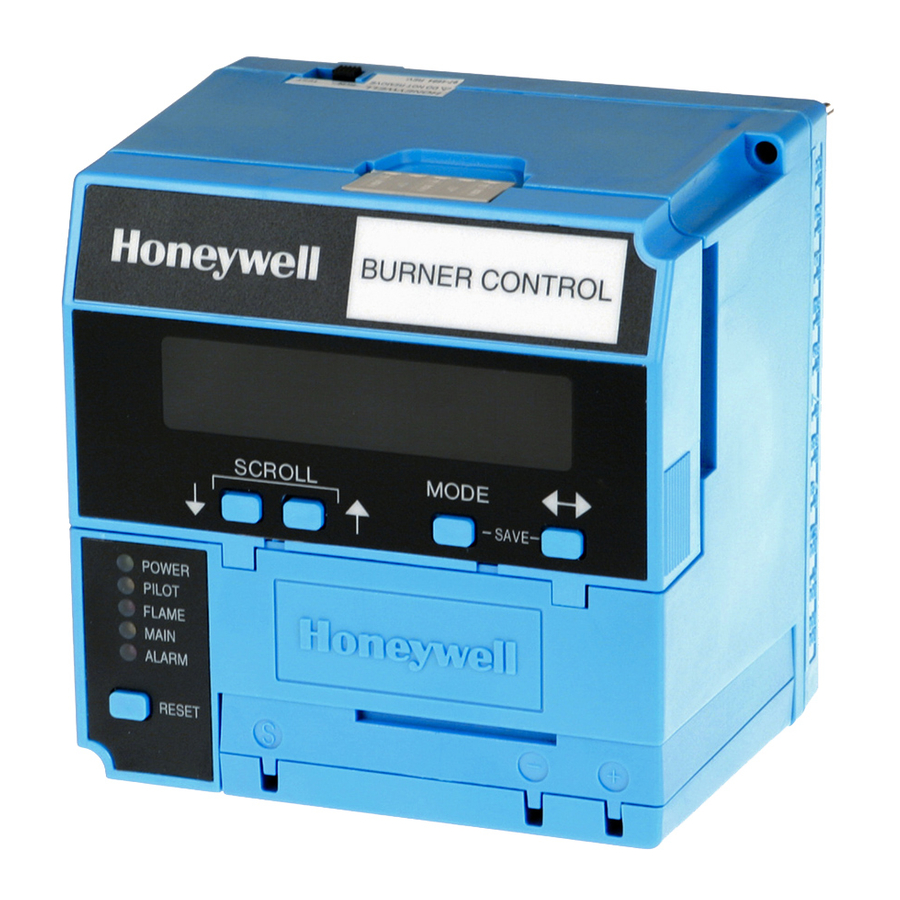
RM7800E,G,L,M; RM7840E,G,L,M
7800 SERIES Relay Modules
APPLICATION
The Honeywell RM7800/RM7840 Relay Modules are
microprocessor-based integrated burner controls for
automatically fired gas, oil, or combination fuel single burner
applications. The RM7800/RM7840 Relay Modules are used
for UL/CSA On/Off, UL/CSA Modulating, and FM/IRI
Modulating burner applications. The RM7800/RM7840 system
consists of a Relay Module. Keyboard Display Modules
(standard with RM7800), Dust Cover (standard with RM7840),
Subbase, Amplifier, and Purge Card. Options include DATA
CONTROLBUS MODULE™, Remote Display Mounting, First-
Out Expanded Annunciator and Communications through
Modbus™.
Functions provided by the RM7800/RM7840 include
automatic burner sequencing, flame supervision, system
status indication, system or self-diagnostics and
troubleshooting. The RM7800/RM7840 is a solid state
replacement for the electromechanical R4140 Automatic
Programming Control.
This document provides installation and static checkout
instructions. Other applicable publications are:
65-0084:Q7800A,B 22-Terminal Wiring Subbase Product
Data.
65-0089:ST7800A Plug-In Purge Timer Installation
Instructions.
65-0090:S7800A Keyboard Display Module Product Data.
65-0091:S7810A Data ControlBus Module™ Product Data.
65-0095:S7820 Remote Reset Module Product Data.
65-0097:221729C Dust Cover Packing Sheet.
65-0101:S7830 Expanded Annunciator Product Data.
65-0109:R7824, R7847, R7848, R7849, R7851, R7852,
R7861, R7886 Flame Amplifiers for the 7800 SERIES
Product Data.
65-0131:221818A Extension Cable Assembly Product
Data.
65-0229:7800 SERIES RELAY MODULES Checkout and
Troubleshooting Product Data.
65-0249:S7810M ModBus™ Module Product Data.
SPECIFICATIONS
Electrical Ratings, see Table 3:
Voltage and Frequency: 120 Vac (+10/-15%), 50 or 60 Hz
(±10%).
Power Dissipation: RM7800/RM7840: 10W maximum.
INSTALLATION INSTRUCTIONS
Maximum Total Connected Load: 2000 VA.
Fusing: 15A maximum, Type SC or equivalent Fast Blow.
Environmental Ratings:
Ambient Temperature:
Operating: -40°F to +140°F (-40°C to +60°C).
Storage: -40°F to +150°F (-40°C to +66°C).
Humidity: 85% relative humidity continuous, noncondensing.
Vibration: 0.5G environment.
SIL 3 Capable:
SIL 3 Capable in a properly designed Safety Instrumented
System. See form number 65-0312 for Certificate Agree-
ment.
Approvals:
Underwriters Laboratories Inc. Listed: File No. MP268,
Guide No. MCCZ.
Canadian Standards Association Certified: LR9S329-3.
Factory Mutual Approved: Report No. J.I.1V9A0.AF.
Swiss Re (formerly IRI): Acceptable.
Federal Communications Commission, Part 15,
Class B—Emissions.
INSTALLATION
When Installing this Product...
1. Read these instructions carefully. Failure to follow
them could damage the product or cause a hazardous
condition.
2. Check the ratings given in the instructions and marked
on the product to make sure the product is suitable for
the application.
3. Installer must be a trained, experienced, flame
safeguard service technician.
4. After installation is complete, check out the product
operation as provided in these instructions.
WARNING
Fire or Explosion Hazard.
Can cause property damage, severe injury,
or death.
To prevent possible hazardous burner operation, verify
safety requirements each time a control is installed on
a burner.
SIL
3
Capable
66-1085-04
Table of Contents

Related Manuals for Honeywell RM7800E


Summary of Contents for Honeywell RM7800E
-
Page 1: Specifications
RM7800E,G,L,M; RM7840E,G,L,M 7800 SERIES Relay Modules APPLICATION The Honeywell RM7800/RM7840 Relay Modules are microprocessor-based integrated burner controls for automatically fired gas, oil, or combination fuel single burner applications. The RM7800/RM7840 Relay Modules are used for UL/CSA On/Off, UL/CSA Modulating, and FM/IRI Modulating burner applications. -
Page 2: Location
RM7800E,G,L,M; RM7840E,G,L,M 7800 SERIES RELAY MODULES WARNING Electrical Shock Hazard. Can cause serious injury or death. Disconnect the power supply before beginning installation. More than one power supply disconnect may be required. IMPORTANT 1. Wiring connections for the relay modules are unique;... -
Page 3: Final Wiring Check
Data ControlBus Module™ Remote Reset Module 13 Vdc full-wave rectified transformer power input. RM7800E,G,L,M; RM7840E,G,L,M 7800 SERIES RELAY MODULES c. Remote Reset leadwires—The maximum length of wire is 1000 feet to a Remote Reset pushbutton. d. Data Controlbus Module™—The maximum Data Controlbus Module™... -
Page 4: Internal Block Diagram
RM7800E,G,L,M; RM7840E,G,L,M 7800 SERIES RELAY MODULES RUN/TEST SWITCH RESET PUSHBUTTON STATUS LEDs PRE-IGNITION INTERLOCK LIMITS CONTROLLER KEYBOARD DISPLAY MODULE RS485 COMMUNICATIONS PROVIDE DISCONNECT MEANS AND OVERLOAD PROTECTION AS REQUIRED. Fig. 1. Internal block diagram of the RM7800L/RM7840L (See Fig. 2, 3, 4 or 5 66-1085—04... -
Page 5: Recommended Grounding Practices
2000 VA maximum connected load to relay module assembly. See tables 4 and 5. RM7800E,G,L,M; RM7840E,G,L,M 7800 SERIES RELAY MODULES Table 2. Recommended Grounding Practices. 1. Use to provide a connection between the subbase and the control panel of the equipment. - Page 6 RM7800E,G,L,M; RM7840E,G,L,M 7800 SERIES RELAY MODULES Pilot Fuel 8 No Load No Load No Load No Load 4.5A ignition. 50 VA Pilot Duty plus 4.5A ignition. Mounting RM7800/RM7840 Relay Module (Fig. 5) 1. Mount the RM7800/RM7840 vertically on the Q7800 Subbase, or mount horizontally with the knife blade terminals pointing downward.
-
Page 7: Wiring Subbase Connections
FOR THE R7800/R7840E: THE HIGH FIRE SWITCH MUST BE WIRED CORRECTLY TO PERFORM ENERGY SAVING PURGE FUNCTIONS. THE BURNER/BLOWER MOTOR DOES NOT START UNTIL THE HIGH FIRE SWITCH MAKES. RM7800L1053, RM7840L1026: TERMINAL 21 PROVIDES INTERMITTENT PILOT FUNCTION. Fig. 2. Wiring subbase and sequence for RM7800E,L/RM7840E,L. RM7800E,G,L,M; RM7840E,G,L,M 7800 SERIES RELAY MODULES SERIES 90... - Page 8 RM7800E,G,L,M; RM7840E,G,L,M 7800 SERIES RELAY MODULES 120V ALARM BURNER MOTOR (BLOWER) BURNER CONTROLLER/LIMITS RUNNING INTERLOCKS (INC. AIR FLOW SWITCH) 10 SEC. INTERRUPTED PILOT/IGNITION MAIN FUEL VALVE(S) 5 SECOND IGNITION (EARLY SPARK TERMINATION) FLAME DETECTOR INITIATE (INITIAL POWERUP ONLY) POWER DISPLAY...
- Page 9 FLAME SAFE START CHECK SIGNAL RM7800M/7840M SWITCHING MOTOR ACTION DAMPER MOTOR Fig. 4. Wiring subbase and sequence for RM7800M/RM7840M. RM7800E,G,L,M; RM7840E,G,L,M 7800 SERIES RELAY MODULES COMMON FOR DIRECT SPARK IGNITION (OIL OR GAS) MODULATE DAMPER MOTOR LOW FIRE START SWITCH 120V, 50/60 Hz POWER SUPPLY.
-
Page 10: Safety Shutdown
RM7800E,G,L,M; RM7840E,G,L,M 7800 SERIES RELAY MODULES PURGE TIMER SEQUENCE STATUS LED PANEL RESET BUTTON KEYBOARD DISPLAY MODULE (STANDARD ON RM7800E,G,L,M) SC RO LL Fig. 5. RM7800/RM7840 Relay Module exploded view. SAFETY SHUTDOWN Safety Shutdown (Lockout) occurs if any of the following occur during the indicated period: 1. -
Page 11: Sequence Of Operation
RM7800/RM7840E,L does not begin until the Lockout Interlock String and High Fire Switch are both closed. The blower motor output for the RM7800E is not energized until the High Fire Switch is closed. c. The Preignition Interlock input must remain closed throughout PREPURGE;... - Page 12 RM7800E,G,L,M; RM7840E,G,L,M 7800 SERIES RELAY MODULES terminal 21. The RM7800/RM7840G has an interrupted or intermittent pilot valve, terminal 21, depending on the selection of configuration jumper 2. The RM7800/RM7840E,L has a fifteen-second interrupted pilot valve, terminal 21. All of the RM7800/RM7840s have a ten-second interrupted pilot valve/ignition, terminal 8.
-
Page 13: Settings And Adjustments
PFEP is selected or during the first three seconds when a four second PFEP is selected, RM7800E,G,L,M; RM7840E,G,L,M 7800 SERIES RELAY MODULES allowing pilot-turn-down test and other burner adjustments to be made. This activates a fifteen second flameout timer that permits pilot flame adjustment without nuisance safety shutdowns. -
Page 14: Site Configurable Jumper Options
RM7800E,G,L,M; RM7840E,G,L,M 7800 SERIES RELAY MODULES Jumper Number Description Pilot Flame Establishing Period (PFEP) Pilot Valve /Main Flame Establishing Period (MFEP) Start-up Interlock Check Pilot Valve /First Stage Oil Valve (Valve/Start) Terminal 21. A 30 second MFEP can be accomplished by adding a jumper wire between Terminals 19 and 5. -
Page 15: Static Checkout
19-L2 RM7840E,L 14-13 RM7800E,G,L; 15-13 — RM7840E,G,L RM7800E,G,L,M; RM7840E,G,L,M 7800 SERIES RELAY MODULES Table 8. Static Checkout. Normal Operation Line voltage at Terminal 4. 1. Master Switch. 2. Power connected to the Master Switch. 3. Overload protection (fuse, circuit breaker, Line voltage at Terminal 6. - Page 16 RM7800E,G,L,M; RM7840E,G,L,M 7800 SERIES RELAY MODULES RM7800/ Test RM7840 Test Models Jumpers Voltmeter RM7800M; 14-13 — RM7840M with open damper contacts.. RM7800M; 18-L2 RM7840M with open damper contacts.. RM7800M; 18-L2 RM7840M with open damper 4-13 contacts.. Final CAUTION Equipment Damage Hazard.