Quick Links
See also:
Operating Manual
1
A
B
C
D
E
-
Mar 15,2012
SYMBOL
DATE
MODEL HV-HD33
DESIGNED
DATE
F
CHECKED
DATE
1
2
HV-HD33
Tentative version
Color Camera
Specification
TOLERANCE
APPROVED
DATE
UNIT
STORED
DATE
SCALE
2
3
For under development,
this specification may change.
(first edition)
DESCRIPTION
Prod. Code - Order No.
TITLE
HV-HD33 specification
DWG.
No.
3
4
S.Ikeda
S.Ikeda
(DRAWN)
DESIGNED
REV.
0
SHEET
1
7
4
DF022-4PE-T1
A
B
C
D
E
F

Related Manuals for Hitachi HV-HD33


Summary of Contents for Hitachi HV-HD33
-
Page 1: Color Camera
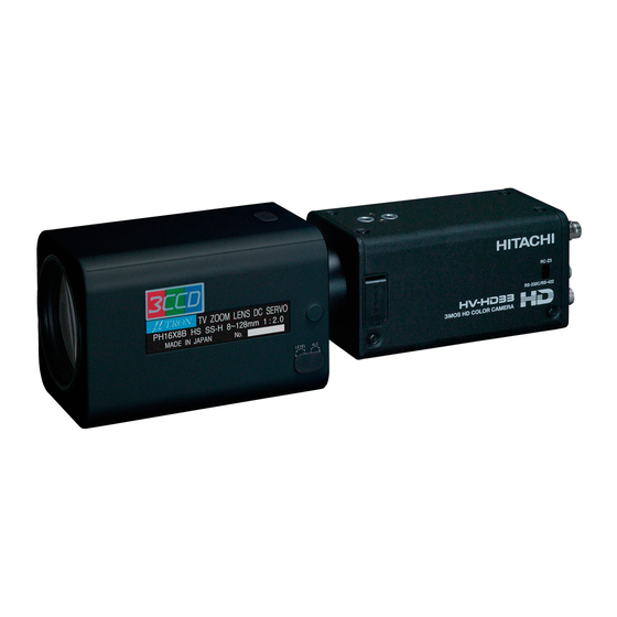
Specification For under development, this specification may change. (first edition) Mar 15,2012 S.Ikeda S.Ikeda SYMBOL DATE DESCRIPTION (DRAWN) DESIGNED TOLERANCE MODEL HV-HD33 Prod. Code - Order No. DESIGNED DATE APPROVED DATE TITLE REV. UNIT CHECKED DATE STORED DATE HV-HD33 specification... - Page 2 The Hitachi color camera HV-HD33 is an HDTV/SDTV multi format camera that supports the 1080i or 720p or 480i or 576i scan formats. The HV-HD33 is a small box type camera by combination between newly developed 1/3 size MOS image sensor, C-mount prism and the Hitachi’s digital signal processing technology.
- Page 3 3. Specification (1) Scan system HDTV system 4 mode 1080/59.94i, 1080/50i, 720/59.94p, 720/50p SDTV system 4 mode 576/50i(4:3), 576/50i(16:9), 480/59.94i(4:3), 480/59.94i(16:9) (2) Image sensor 1/3-size MOS image sensor Total pixels 1376(H) x 1070(V) Effective pixels 1280(H) x 720(V) Effective image area 4.80 mm(H) x 3.84 mm(V) (3) Imaging system R, G, B 3-MOS...
- Page 4 (21) Mass Approx. 550g (22) Ambient temperature Operation -10 to 40 ℃ Storage -20 to 60 ℃ 4. Standard composition Color camera HV-HD33 Power plug R03-P3F Lens plug E4-191J-100 Operation manual 5. Input and output signals 5-1. Input signals (1) Sync input (MULTI connector) ・...
- Page 5 (4) SYNC output (MULTI connector) : 2 Vp-p/75Ω : 2 Vp-p/75Ω SYNC : 0.3 Vp-p/75Ω Note: Please change SYNC input and the SYNC output with an internal switch. (5) Serial data (REMOTE connector, MULTI connector) 1.5 Vp-p ±3 dB (when connected to RC-Z3) RS-232C level (when connected to personal computer) RS-422 level (when connected to personal computer.
- Page 6 REMOTE Pin number Signal name UNREG +12V OUT DC IN Pin number Signal name UNREG +12V IN LENS Pin number Signal name UNREG +12V OUT IRIS CONT 7. Dimensions SHEET DWG. DF022-4PE-S1...
- Page 7 8. Accessory Camera control box RC-Z3 AC Adaptor IA-60a DC cable (For IA-60a) C-501ES 9. System Computer Image Processing & FA Camera Lens RS-232C RS-422 MULTI PC + Frame Grabber HV-HD30 REMOTE SDI OUT DC IN Camera Control Panel RC-Z3 SHEET DWG.