Sony AVD-K800P Service Manual
Compact av system
Hide thumbs
Also See for AVD-K800P:
- Operating instructions manual (84 pages) ,
- Supplementary manual (1 page) ,
- Service manual (26 pages)
Table of Contents
SERVICE MANUAL
Ver 1.0 2003. 05
AVD-K800P is the amplifier, CD/DVD and tuner system in HT-C800DP.
This system incorporates with Dolby* Digital and Dolby Pro Logic (II) adaptive matrix
surround decoder and the DTS** Digital Surround System.
*
Manufactured under license from Dolby Laboratories.
"Dolby", "Pro Logic" and the double-D symbol are trademarks of Dolby Laboratories.
** Manufactured under license from Digital Theater Systems, Inc.
"DTS" and "DTS Digital Surround" are trademarks of Digital Theater Systems, Inc.
AUDIO POWER SPECIFICATIONS
POWER OUTPUT AND TOTAL HARMONIC DISTORTION:
With 6 ohm loads, both channels driven, from 120 – 20,000 Hz; rated 60
watts per channel minimum RMS power , with no more than 0.7 % total
harmonic distortion from 250 milliwatts to rated output (USA model only).
Amplifier section
Rated Power Output at Stereo Mode
60 W + 60 W (6 ohms, at 1 kHz, THD 0.7 %)
Reference Power Output
Front: 100 W/ch (6 ohms at 1 kHz, THD 10 %)
Center*: 100 W (6 ohms at 1 kHz, THD 10 %)
Surround*: 100 W/ch (6 ohms at 1 kHz, THD 10 %)
Sub woofer*: 100 W (6 ohms at 100 Hz, THD 10 %)
* Depending on the sound field settings and the source, there may be no sound output.
Inputs (Analog)
ANALOG IN:
Sensitivity: 500 mV
Impedance: 50 kilohms
Outputs (Analog)
PHONES:
Accepts low- and high-impedance headphones
CD/DVD system
Laser
Semiconductor laser
(DVD: λ = 650 nm)
(CD: λ = 780 nm)
Emission duration: continuous
Signal format system
NTSC/PAL or NTSC
Frequency response (at 2 CH STEREO mode)
DVD (PCM): 2 Hz to 22 kHz (±1.0 dB)
CD: 2 Hz to 20 kHz (±1.0 dB)
Signal-to-noise ratio
More than 80 dB
Harmonic distortion
Less than 0.03 %
FM tuner section
System
PLL quartz-locked digital synthesizer system
Tuning range
North American models: 87.5 – 108.0 MHz (100 kHz step)
Other models:
87.5 – 108.0 MHz (50 kHz step)
Antenna
FM wire antenna
Antenna terminals
75 ohms, unbalanced
Intermediate frequency 10.7 MHz
Sony Corporation
9-877-319-01
2003E16-1
Home Audio Company
© 2003.05
Published by Sony Engineering Corporation
AVD-K800P
Model Name Using Similar Mechanism
Mechanism Type
Optical Pick-up Name
SPECIFICATIONS
AM tuner section
System
Tuning range
North American models: 530 – 1,710 kHz (with the interval set at 10 kHz)
European models:
Mexican models:
Other models:
Antenna
Intermediate frequency 450 kHz
Video section
Inputs
Outputs
General
Power requirements
North American and Mexican models:
European models:
Other models:
Power consumption
Canadian models:
Other models:
Power consumption (at Power Saving Mode):
Dimensions (approx.)
Mass (approx.)
Operating temperature
Operating humidity
Design and specifications are subject to change without notice.
US Model
Canadian Model
AEP Model
UK Model
E Model
NEW
CDM79-DVBU22
TDP022W
PLL quartz-locked digital synthesizer system
531 – 1,710 kHz (with the interval set at 9 kHz)
531 – 1,602 kHz (with the interval set at 9 kHz)
530 – 1,610 kHz (with the interval set at 10 kHz)
530 – 1,610 kHz (with the interval set at 10 kHz)
531 – 1,602 kHz (with the interval set at 9 kHz)
AM loop antenna
Video:
1 Vp-p 75 ohms
Video:
1 Vp-p 75 ohms
Component: Y: 1 Vp-p 75 ohms
P
/C
: 0.7 Vp-p 75 ohms
B
B
P
/C
: 0.7 Vp-p 75 ohms
R
R
120 V AC, 60 Hz
230 V AC, 50/60 Hz
120/220 V AC, 50/60 Hz
240 VA
190 W
0.5 W
430 × 170 × 450 mm (17 × 6
× 17
7
/
8
(w/h/d) incl. projecting parts
11.5 kg (25 lb 6 oz.)
5˚C to 35˚C (41˚F to 95˚F)
5 % to 90 %
COMPACT AV SYSTEM
7
/
inches)
8
Table of Contents

Related Manuals for Sony AVD-K800P


Summary of Contents for Sony AVD-K800P
-
Page 1: Specifications
AEP Model UK Model E Model AVD-K800P is the amplifier, CD/DVD and tuner system in HT-C800DP. This system incorporates with Dolby* Digital and Dolby Pro Logic (II) adaptive matrix Model Name Using Similar Mechanism surround decoder and the DTS** Digital Surround System. - Page 2 CRITIQUES POUR LA SÉCURITÉ DE FONCTIONNEMENT. NE COMPONENTS WITH SONY PARTS WHOSE PART NUMBERS REMPLACER CES COMPOSANTS QUE PAR DES PIÈSES SONY APPEAR AS SHOWN IN THIS MANUAL OR IN SUPPLEMENTS DONT LES NUMÉROS SONT DONNÉS DANS CE MANUEL OU PUBLISHED BY SONY.
- Page 3 AVD-K800P MODEL IDENTIFICATION NOTES ON HANDLING THE OPTICAL PICK-UP BLOCK — BACK PANEL — OR BASE UNIT The laser diode in the optical pick-up block may suffer electrostatic break-down because of the potential difference generated by the charged electrostatic load, etc. on clothing and the human body.
-
Page 4: Table Of Contents
AVD-K800P TABLE OF CONTENTS 1. GENERAL ·········································································· 5 2. DISASSEMBLY 2-1. Case ··············································································· 7 2-2. Loading (PANEL) ························································· 8 2-3. CD Mechanism Deck (CDM79-DVBU22) ··················· 8 2-4. Front Panel Assy ···························································· 9 2-5. DISPLAY Board, OPEN/CLOSE Board, POWER SWITCH Board, HP Board ···························· 9 2-6. -
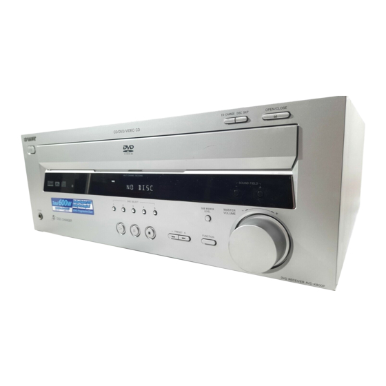
Page 5: General
AVD-K800P SECTION 1 GENERAL This section is extracted from instruction manual. Front Panel EX-CHANGE DISC SKIP OPEN/CLOSE MULTI CHANNEL DECODING SOUND FIELD – DISC SELECT – SUB WOOFER MASTER LEVEL VOLUME PHONES PRESET FUNCTION 1 ?/1 (power switch) (29) 9 SOUND FIELD +/– (50) - Page 6 ENTER The remote control of the unit employs command Executes the items or settings. signals in common with other Sony DVD products. wj CLEAR Thus, depending on the button, other Sony DVD Press to return to the Continuous play, etc.
-
Page 7: Disassembly
AVD-K800P SECTION 2 DISASSEMBLY The equipment can be removed using the following procedure. CASE LOADING (PANEL) CD MECHANISM DECK (CDM79-DVBU22) TABLE ASSY FRONT PANEL ASSY TUNER UNIT (TM301), I/O BOARD DISPLAY BOARD, OPEM/CLOSE BOARD, SE-130 BOARD PICKUP UNIT POWER SWITCH BOARD,... -
Page 8: Loading (Panel)
AVD-K800P 2-2. Loading (PANEL) 3 loading (panel) gear (shaft) 2 table hole of chassis 1 Turn the gear (shaft) in the direction of the arrow. 2-3. CD Mechanism Deck (CDM79-DVBU22) 5 three screws (BVTP 3 × 8) CD mechanism deck... -
Page 9: Front Panel Assy
AVD-K800P 2-4. Front Panel Assy connector (CNP100) chassis assy 3 two screws (+BVTP 2.6 2 screw (+BVTP 2.6 flat type wire (25 core) (CNS901) 1 screw (+BVTP 2.6 7 front panel assy 4 five screws (+BVTP 2.6 2-5. DISPLAY Board, OPEN/CLOSE Board, POWER SWITCH Board, HP Board... -
Page 10: Tuner Unit (Tm301), I/O Board
AVD-K800P 2-6. Tuner Unit (TM301), I/O Board 1 wire (flat type) (11 core) 4 connector (CNP3) 3 tuner unit (TM301) 5 wire (flat type) (17 core) 6 wire (flat type) (11 core) 8 screw (+BVTP 3 × 8) 7 wire (flat type) (25 core) q;... -
Page 11: Dc Fan (Fan1)
AVD-K800P 2-8. DC Fan (FAN1) 3 DC fan (FAN1) 1 four screws (+BVTP 3 × 8) 2 connector (CNP801) 2-9. MAIN Board qs four screws 3 connector qa five screws (+BVTP 3 × 6) (CN804) (+BVTP 3 × 8) 4 connector... -
Page 12: Table Assy
AVD-K800P 2-10. Table Assy 1 floating screw (+PTPWH M2.6) 2 tray 4 screw (+BTP2.6 5 claw 6 plate (guide) flat type wire (6 core) (CN002) table assy 7 screw (+BTP2.6 9 plate (guide) 8 claw... -
Page 13: Se-130 Board
AVD-K800P 2-11. SE-130 Board flat type wire 4 two screws (6 core) (CN101) 6 SE-130 board (+BTP 2.6 connector (CN102) 3 claw 2 claw 7 two screws (+BTP 2.6 qa td unit assy 0 td belt 9 td motor assy... -
Page 14: Dc Motor (M001)
AVD-K800P 2-12. DC Motor (M001) 6 DC motor (M001) 5 connector (CN004) 3 belt (loading) 2 gear (loading A) 4 two screws 1 screw (+P 2.6 × 4) (+PTPWH M2.6) 2-13. Pickup Unit Section 1 two screws (+BV B3) 2 chuck assy 3 screw (+PTPWH M2.6) -
Page 15: Rf Board
AVD-K800P 2-14. RF Board 6 three step screws (M) 7 three insulators 8 pickup unit 4 flexible flat cable (9 core) 3 flexible flat cable (24 core) (CN003) (CN001) 2 claw 9 holder (BU) assy 5 RF board 1 two screws... -
Page 16: Test Mode
AVD-K800P SECTION 3 TEST MODE [Version Display Mode] Press the > button and confirm all segments and all LEDs turn off. * The software version is displayed. Press the > button and the message “STRU *.**” is Procedure: displayed. Press the ?/1 button to turn the set on. - Page 17 AVD-K800P [DVD OSD TEST MODE] • Example display [GENERAL DESCRIPTION] ### Syscon Diagnosis ### The Test Mode allows you to make diagnosis and adjustment easily using the remote commander and monitor TV. The instructions, Diag All Check diagnostic results, etc. are given on the on-screen display (OSD).
- Page 18 AVD-K800P 0-2-5. Region 1-1. DVD-SL (single layer) Model destination code is displayed. (2 digits number) Press the [1] key on the remote commander and insert a DVD single layer disc following the message. Then the adjustment will be made 0-3. EEPROM Check through the steps below, then adjusted values will be written to the 0-3-1.
- Page 19 AVD-K800P 24. Auto track gain adjust DRIVE MANUAL OPERATION Search Check Note: This mode is used for design, and not used in service fundamen- 25. 32Tj forward tally. 26. 32Tj reverse On the Test Mode Menu screen, press the key on the remote 27.
- Page 20 AVD-K800P 2-1. Disc Type 2-1-3. Disc Type CD It sets up so that it may judge as a disc type of specification of the disc with which the set was inserted. Disc Type : CD disc (normal speed, 12 cm)
- Page 21 AVD-K800P 2-3. Track/Layer Jump 2-5. EEPROM Write Adjust Track/Layer Jump EEPROM Write Adjust FWD R.Lj L0>L1 REV L.Lj L1>L0 1. Focus Offset 3.500Tj Fine FWD U.Fj L0>L1 2. Focus Gain 4.500Tj Fine REV D.Fj L1>L0 3. Trk. Offset Coarse 5.10kTj Dirc 4.
- Page 22 AVD-K800P 2-7. Disc Check Memory MECHA AGING On the Test Mode Menu screen, selecting executes the aging of Disc Check Memory the mechanism deck. 1. SL Disc check 2. SL Disc check ### Aging Test MENU ### 3. SL Disc check Pls use over 40min.
- Page 23 AVD-K800P • Code list of Emergency History aa: Initialization is completed or not. 10: Communication to RF AMP (IC001) failed. : Complete. 11: Each servo for focus, tracking, and spindle is unlocked. other number : Not complete. 12: Check sum error of EEPROM (IC204).
- Page 24 AVD-K800P VERSION INFORMATION On the Test Mode Menu screen, selecting displays the ROM version and region code. The parenthesized hexadecimal number in version field is checksum value of ROM. ## Version Information ## IF con. Ver.x. xx SYScon. Ver.x. xx...
-
Page 25: Diagrams
AVD-K800P SECTION 4 DIAGRAMS 4-1. Circuit Board Location THIS NOTE IS COMMON FOR PRINTED WIRING BOARDS AND SCHEMATIC DIAGRAMS. (In addition to this, the necessary note is printed in each block.) For schematic diagrams. SE-130 BOARD For printed wiring boards. -
Page 26: Block Diagrams
AVD-K800P 4-2. Block Diagrams — RF SERVO Section — 117 RFIN SD0 – SD7 VIDEO SECTION ATOP DVDRFP RFAC 50 RFAC 160 MDAT PCMD RFSIN ATON BCLK BCLK 158 BCLK LRCK LRCK LRCK 163 LRCK XDCK XDCK, XSAK, SDEF, XSHD... -
Page 27: Video Section
AVD-K800P — VIDEO Section — J302 (1/2) IC1302 VIDEO INPUT IC1301 VIDEO SELECTOR VIDEO AMP, 75 DRIVER VIDEO IN IC256 RF SERVO D-FF SECTION J302 (2/2) 1 V_IN VOUT MONITOR 4 VIN VOUT VIDEO OUT 3 DVD VDAC_0 CYOUT VDAC_2... -
Page 28: Audio Section
AVD-K800P — AUDIO Section — IC302 IC1312 D/A CONVERTER SOUND PROCESSOR IC1310 DATA0 VIDEO 31 DATA4 VOUT1 44 INFLA L OUT SECTION DATA1 45 DATA1 DATA2 46 DATA2 DATA3 47 DATA3 43 INFRA R OUT VOUT2 LRCK-ZIVA 41 LRCK IC1311... -
Page 29: Amp Section
AVD-K800P — AMP Section — J100 PHONES IC500 RY881 R-CH POWER AMP D528 Q881 RELAY Q573 DRIVE +V OUT2 BOOSTER TM601 Q571,572 LIMITER SPEAKERS FRONT L RY501 R-ch is omitted due D577 Q551 to same as L-ch. Q577 RELAY AF POWER... -
Page 30: Power Section
AVD-K800P — POWER Section — T901 MAIN TRANSFORMER IC901 (3/3) SYSTEM CONTROLLER D801 +46V Q801 IC100 -30V FL DRIVER -30V (FL) REGULATOR FL_DATA 7 DIN S100 – 104, 117 -46V S105 – 110, FL_CLK 8 CLK S111 – 115 9 STB... -
Page 31: Printed Wiring Board - Rf Section
AVD-K800P 4-3. Printed Wiring Board — RF Section — • See page 25 for Circuit Boards Location. RF BOARD RF BOARD (SIDE A) (SIDE B) OPTICAL PICK-UP BLOCK (TDP022W) IC001 DMB03 BOARD CN501 (Page 33) (11) (11) 1-684-822- 1-684-822- • Semiconductor Location Ref. -
Page 32: Schematic Diagram - Rf Section
AVD-K800P 4-4. Schematic Diagram — RF Section — • See page 53 for Wavefoms. • See page 54 for IC Block Diagrams. C006 C028 C027 R026 C013 C031 1000p CN002 C030 0.01 C026 C025 R023 C029 0.01 C024 C035 JL005 0.01... -
Page 33: Printed Wiring Board - Dmb Section (Side A)
AVD-K800P 4-5. Printed Wiring Board — DMB Section (SIDE A) — • : Uses unleaded solder. • See page 25 for Circuit Boards Location. MAIN BOARD I/O BOARD CNS905 CNS303 (Page 45) (Page 43) NOT USED NOT USED • Semiconductor... -
Page 34: Printed Wiring Board - Dmb Section (Side B)
AVD-K800P 4-6. Printed Wiring Board — DMB Section (SIDE B) — • : Uses unleaded solder. • See page 25 for Circuit Boards Location. IC352 IC372 • Semiconductor Location IC333 Ref. No. Location D392 D393 D394 D1101 D1102 D1201 D1202... -
Page 35: Schematic Diagram - Dmb Section (1/8)
AVD-K800P 4-7. Schematic Diagram — DMB Section (1/8) — • See page 53 for Wavefoms. • See page 55, 56 for IC Block Diagrams. R309 CN107 CL309 R310 C309 100p CL310 R311 C308 100p R312 CL311 R308 CL312 D392 1SS355TE-17... -
Page 36: Schematic Diagram - Dmb Section (2/8)
AVD-K800P 4-8. Schematic Diagram — DMB Section (2/8) — • See page 56 for IC Block Diagrams. R587 CL505 CL504 CL503 CL502 FL502 C567 CL501 C568 R569 R545 C522 R548 CN501 6.3V CL544 R9988 R537 CL537 C592 R536 R694 CL536... -
Page 37: Schematic Diagram - Dmb Section (3/8)
AVD-K800P 4-9. Schematic Diagram — DMB Section (3/8) — • See page 57 for IC Block Diagrams. IC703(2/2) R784 C701 R786 NJM3404AV( 100k TE2) R700 TP703 C782 R787 100k 8.2k 0.0015 50V B FL701 R788 100k C703 C715 C717 FL706 0.0015... -
Page 38: Schematic Diagram - Dmb Section (4/8)
AVD-K800P 4-10. Schematic Diagram — DMB Section (4/8) — JL521 C527 0.01 C526 R543 R547 R581 R589 R580 C519 0.01 R579 8.2k C514 IC501 0.01 FAN8035L R534 R535 R533 R532 R530 R531 C926 C512 R529 0.01 C927 0.01 R528 R525... -
Page 39: Schematic Diagram - Dmb Section (5/8)
AVD-K800P 4-11. Schematic Diagram — DMB Section (5/8) — • See page 53 for Wavefoms. • See page 57 for IC Block Diagrams. R903 C902 FL901 0.01 IC902 TC7S32FU-T R901 E85L C901 Q901 DTC114TE-TL IC904 TC7W74FK-T E85L R991 CL922 R992... -
Page 40: Schematic Diagram - Dmb Section (6/8)
AVD-K800P 4-12. Schematic Diagram — DMB Section (6/8) — CN202 CN105 IC255 TC7S00FU (TE85R) C283 0.01 R223 R9998 R9994 R9999 R224 R218 R217 IC256 SN74LV573A C284 0.01 50V F R201 R270 R278 R279 R280 R281 R282 IC258 SN74LV573A C414 C412... -
Page 41: Schematic Diagram - Dmb Section (7/8)
AVD-K800P 4-13. Schematic Diagram — DMB Section (7/8) — • See page 53 for Wavefoms. R265 R266 R267 R263 R264 R225 R226 R228 R251 C226 R233 C229 0.01 R259 4.7k R254 4.7k C241 0.01 C288 0.01 R240 R234 Q202 DTC114TE-TL C242 0.01... -
Page 42: Schematic Diagram - Dmb Section (8/8)
AVD-K800P 4-14. Schematic Diagram — DMB Section (8/8) — • See page 55 for IC Block Diagrams. IC203 MT48LC4M32B2TG-6 C218 0.01 C255 10 10V F C220 0.01 C259 FL203 FL204 C258 0.01 C227 0.01 RB10 RB12 C205 0.01 C235 0.01... -
Page 43: Printed Wiring Board - I/O Section
AVD-K800P 4-15. Printed Wiring Board — I/O Section — • : Uses unleaded solder. • See page 25 for Circuit Boards Location. VIDEO COMPONENT AUDIO AUDIO MONITOR VIDEO OUT VIDEO IN VIDEO OUT IC1307 • Semiconductor IC1301 Location IC1302 IC1303 Ref. -
Page 44: Schematic Diagram - I/O Section
AVD-K800P 4-16. Schematic Diagram — I/O Section — • See page 53 for Wavefoms. • See page 58 for IC Block Diagrams. CNS305 C1403 R1406 47 25V 8.2k R1405 C1401 8.2k 47 25V TM301 R1404 C1400 8.2k 47 25V R1403 C1402 8.2k... -
Page 45: Printed Wiring Board - Main Section
AVD-K800P 4-17. Printed Wiring Board — MAIN Section — • : Uses unleaded solder. • See page 25 for Circuit Boards Location. • Semiconductor Location Ref. No. Location Ref. No. Location D426 I-11 Q426 I-12 D448 G-10 Q441 D449 G-10... -
Page 46: Schematic Diagram - Main Section (1/3)
AVD-K800P 4-18. Schematic Diagram — MAIN Section (1/3) — • See page 53 for Wavefoms. • See page 59 for IC Block Diagrams. CNS904 CNP910 CNS901 IC830 IC831 MTZJ-T-72-4.7A BA6956AN C833 C831 0.01 R832 2.2k C832 R833 R830 2.2k C839 C838 0.01... -
Page 47: Schematic Diagram - Main Section (2/3)
AVD-K800P 4-19. Schematic Diagram — MAIN Section (2/3) — • See page 59 for IC Block Diagrams. IC400 R427 4.7k C423 C425 R423 220p 500V Q425 2SA988TP- TPFAEA R400 TM601 R421 R422 Q423 L640 Q421 2.2k R426 MN2488 R429 R433... -
Page 48: Schematic Diagram - Main Section (3/3)
AVD-K800P 4-20. Schematic Diagram — MAIN Section (3/3) — • See page 59 for IC Block Diagrams. D801 RBV-602LF-A W410 CN804 W411 C801 C803 0.22 6800 100V C802 0.22 C804 100V 6800 W451 W450 CNP911 IC906 C825 T901 SI-8033JF C824... -
Page 49: Printed Wiring Board - Voltage Selector, Loading Section
AVD-K800P 4-21. Printed Wiring Board — VOLTAGE SELECTOR, LOADING Section — • : Uses unleaded solder. • See page 25 for Circuit Boards Location. M001 TURN TABLE MOTOR SE-130 BOARD T901 EXCEPT E51 MAIN BOARD CNP902 (Page 45) MAIN BOARD... -
Page 50: Schematic Diagram - Loading Section
AVD-K800P 4-22. Schematic Diagram — LOADING Section — CN001 CN003 CN004 S001 CN002 CN102 CN101 M001 PH101 RPR-220C1N PH102 RPI-392... -
Page 51: Printed Wiring Board - Display Section
AVD-K800P 4-23. Printed Wiring Board — DISPLAY Section — • : Uses unleaded solder. • See page 25 for Circuit Boards Location. S109 EX-CHANGE OPEN/CLOSE DISC SKIP • Semiconductor Location Ref. No. Location MULTI CHANNEL DECODING D100 E-10 D101 E-10... -
Page 52: Schematic Diagram - Display Section
AVD-K800P 4-24. Schematic Diagram — DISPLAY Section — • See page 60 for IC Block Diagrams. IC102 R141 NJL63H400A-1 R140 C144 C145 J100 C102 R118 R172 R123 R122 R121 R120 4.7k 2.2k 2.2k RV100 R116 CNP100 C148 S117 S103 S102... - Page 53 AVD-K800P • Waveforms -RF Board- IC001 1 (DVDRFP) IC001 el (TE) IC001 r; (FE) IC001 tj (RFAC) 0.3 Vp-p 0.5 Vp-p 800 mVp-p 1.3 Vp-p 200 mV/DIV, 100 ns/DIV 500 mV/DIV, 1 ms/DIV 100 mV/DIV, 1 ms/DIV 500 mV/DIV, 100 ns/DIV...
-
Page 54: Ic Block Diagrams
AVD-K800P 4-25. IC Block Diagrams IC001 CXD1881AR (RF BOARD) 64 63 62 61 60 59 55 54 53 52 FAST ATTACK INPUT OUTPUT HOLD FULL WAVE AGC CHARGE INHIBIT RECTIFER PUMP PROGRAMMABLE FROM S-PORT EQUALIZER INPUT DVDRFP FILTER BIAS DVDRFN... - Page 55 AVD-K800P IC216 SN74ALVCH16841DGGR (DMB03 BOARD) IC302 PCM1609KPTR (DMB03 BOARD) Power Supply System Clock VCC3 SCKI Manager SCKO Output Amp and AGND3 Low-pass Filter VCC4 Output Amp and Low-pass Filter AGND4 Enhanced Output Amp and Oversampling Multi-level LRCK Low-pass Filter VOUT8...
- Page 56 AVD-K800P IC352 PCM1800E/2K (DMB03 BOARD) 15 14 13 DIGITAL ∑ MODULATOR 1/64 SERIAL I/O DECIMATION INTERFACE FILTER & & MODE/FORMAT LOW-CUT CONTROL DIGITAL ∑ FILTER MODULATOR SINGLE-END SINGLE-END CLOCK/ DEFERENTIAL REFERENCE DEFERENTIAL TIMING CONTROL RESET/ CONVERTER CONVERTER POWER CONTROL IC509 CXD3068Q (DMB03 BOARD)
- Page 57 AVD-K800P IC706 MSM51V18165F-60TSKR1 (DMB03 BOARD) 40 – 36 34 33 REFRESH INTERNAL TIMING CONTROL ADDRESS GENERATOR CLOCK COUNTER CONTROLLER OUTPUT INPUT BUFFER BUFFER COLUMN CONTROLLER ADDRESS ADDRESS BUFFERS BUFFERS SENSE COLUMN AMPLIFIER DECODERS OUTPUT INPUT BUFFER BUFFER MEMORY WORD CELLS...
- Page 58 AVD-K800P IC1301 MM1568 (I/O BOARD) VCC1 VCC2 BIAS 75Ω COUT DRIVER MUTE1 CLAMP GND2 75Ω VOUT DRIVER YC MIX VSAG CLAMP GND2 75Ω YOUT DRIVER BIAS BIAS YSAG GND1 GND1 10 NC 11 GND2 CYIN 12 75Ω CYOUT DRIVER CLP 13...
- Page 59 AVD-K800P IC400, IC500, IC600 uPC2581V-S (MAIN BOARD) BIAS CIRCUIT PROTECTOR REG DRIVE DRIVE DRIVE DRIVE 2 3 4 5 6 8 9 10 11 12 13 14 15 IC830, IC831 BA6956AN (MAIN BOARD) CONTROL LOGIC IC905 NJM2103D (MAIN BOARD) IC906 SI-8033JF (MAIN BOARD)
- Page 60 AVD-K800P IC100 PT6315 (DISPLAY BOARD) Grid driver Multiplexed driver SEG19/GRID10 Command decoder LED1 SEG18/GRID11 LED2 Display memory LED3 SEG17/GRID12 24 bits x 12 words LED4 Timing generator key scan DOUT SEG16/KS16 Key data memory Serial SEG15/KS15 (2 x 16 bits)
-
Page 61: Ic Pin Function Description
AVD-K800P 4-26. IC Pin Function Description • IC207 ZIVA5X-C1F (DVD SYSTEM PROCESSOR)(DMB03 BOARD) Pin No. Pin Name Description VDDP — Power supply terminal (+3.3V) (I/O signal) Address bus HAD15 Data bus (address signal multiplexed) HAD14 Data bus (address signal multiplexed) - Page 62 AVD-K800P Pin No. Pin Name Description MRAS SDRAM row address strobe signal output MCAS SDRAM column address strobe signal output SDRAM write enable signal output (“H” : read, “L” : write) GND25 — Ground terminal (SDRAM I/O signal) VDD25 —...
- Page 63 AVD-K800P Pin No. Pin Name Description MD30 SDRAM data MD31 SDRAM data GND25 — Ground terminal (SDRAM I/O signal) VDD25 — Power supply terminal (+3.3V) (SDRAM I/O signal) VCLK System clock (not used) XCK_I/O_SEL 5.1ch/downmix switch signal output S1 signal output (not used)
- Page 64 AVD-K800P Pin No. Pin Name Description DATA1(FLR) Audio data(Front L/R signal) output VDDP — Power supply terminal (+3.3V) (I/O signal) GNDP — Ground terminal (I/O signal) DATA2(SLR) Audio data(Rear L/R signal) output DATA3(CSW) Audio data(Center/Subwoofer signal) output IEC958 S/PDIF signal (not used)
- Page 65 AVD-K800P Pin No. Pin Name Description TCK signal input RESET ZIVA reset input BUS CLK Not used — Ground terminal (inside core) — Power supply terminal (+1.8V) (inside core) Address bus 3 Address bus 2 GNDP — Ground terminal (I/O signal)
- Page 66 AVD-K800P • IC901 CX973F064R-1 (MECHANISM CONTROLLER)(DMB03 BOARD) Pin No. Pin Name Description NO USE Not used SDEN Serial data enable signal output to DVD/CD RF amplifier DOCTRL/ Digital out on/off control signal output to the digital signal processor ISBTEST “L”: digital out off, “H”: digital out on...
- Page 67 AVD-K800P Pin No. Pin Name Description CONTROL 2 Disc tray out detection signal input terminal Not used GFS DVD Guard frame sync signal input from the DVD decoder MUTE CD Muting on/off control signal output to the digital signal processor “H”: muting on MUTE 2D Muting on/off control signal output to the motor/coil driver “H”: muting on...
- Page 68 AVD-K800P • IC901 PD703033BYGF-M15-3BA (SYSTEM CONTROLLER)(MAIN BOARD) Pin No. Pin Name Description TUN_CLK Clock output to the tuner TUN_LATCH Latch signal output to the tuner I2C_DATA I2C data input/output ZIVA_RST Reset signal output to the DVD system processor (IC207) I2C_CLK...
- Page 69 AVD-K800P Pin No. Pin Name Description FL_DATA Data output to the FL driver (IC100) FL_CLK Clock output to the FL driver (IC100) FL_LATCH Latch signal output to the FL driver (IC100) HP_REY Headphone relay control signal output FRONT_REY Front speaker relay control signal output...
-
Page 70: Exploded Views
AVD-K800P SECTION 5 EXPLODED VIEWS NOTE: • The mechanical parts with no reference • -XX, -X mean standardized parts, so they may The components identified by mark 0 or number in the exploded views are not supplied. have some difference from the original one. -
Page 71: Front Panel Section
AVD-K800P 5-2. Front Panel Section FL100 supplied including RV100 Ref. No. Part No. Description Remark Ref. No. Part No. Description Remark 4-232-113-12 KNOB (VOL) 1-685-957-11 POWER SWITCH BOARD 4-977-358-01 CUSHION A-4732-144-A DISPLAY BOARD, COMPLETE X-4955-389-1 FRONT PANEL ASSY (US) (US,CND,E51,MX) -
Page 72: Chassis Section
AVD-K800P 5-3. Chassis Section not supplied FAN1 supplied F901 Q474 Q473 Q573 Q574 Q423 Q674 TM301 Q424 supplied Q524 Q673 Q523 Q624 Q623 T901 supplied Ref. No. Part No. Description Remark Ref. No. Part No. Description Remark A-4732-139-A MAIN BOARD, COMPLETE (US,CND) -
Page 73: Cd Mechanism Deck Section-1 (Cdm79-Dvbu22)
AVD-K800P 5-4. CD Mechanism Deck Section-1 (CDM79-DVBU22) supplied supplied supplied supplied CD mechanism deck section-2 (CDM79-DVBU22) Ref. No. Part No. Description Remark Ref. No. Part No. Description Remark 3-074-737-01 PLATE (GUIDE) 3-074-717-01 TRAY A-6060-642-A SE-130 MOUNT 4-218-252-51 SCREW (+PTPWH M2.6), FLOATING... -
Page 74: Cd Mechanism Deck Section-2 (Cdm79-Dvbu22)
AVD-K800P 5-5. CD Mechanism Deck Section-2 (CDM79-DVBU22) supplied supplied not supplied M001 not supplied not supplied not supplied Ref. No. Part No. Description Remark Ref. No. Part No. Description Remark 4-218-252-51 SCREW (+PTPWH M2.6), FLOATING 3-053-847-31 INSULATOR 3-074-744-01 GEAR (LOADING A) -
Page 75: Electrical Parts List
AVD-K800P SECTION 6 ELECTRICAL PARTS LIST DISPLAY Note: • CAPACITORS • Due to standardization, replacements in the parts When indicating parts by reference number, uF : F list may be different from the parts specified in the please include the board name. - Page 76 AVD-K800P DISPLAY DMB03 Ref. No. Part No. Description Remarks Ref. No. Part No. Description Remarks R109 1-216-809-11 METAL CHIP 1/16W A-4732-136-A DMB03 BOARD, COMPLETE ********************** R110 1-216-809-11 METAL CHIP 1/16W R111 1-216-809-11 METAL CHIP 1/16W < CAPACITOR > R112 1-216-809-11 METAL CHIP...
- Page 77 AVD-K800P DMB03 Ref. No. Part No. Description Remarks Ref. No. Part No. Description Remarks C271 1-164-947-11 CERAMIC CHIP 0.01uF C504 1-127-772-81 CERAMIC CHIP 33000PF C506 1-164-934-11 CERAMIC CHIP 330PF 10.00% 50V C272 1-164-947-11 CERAMIC CHIP 0.01uF C508 1-164-937-11 CERAMIC CHIP 0.001uF...
- Page 78 AVD-K800P DMB03 Ref. No. Part No. Description Remarks Ref. No. Part No. Description Remarks C717 1-164-943-11 CERAMIC CHIP 0.01uF 10.00% 16V C916 1-126-209-11 ELECT CHIP 100uF 20.00% 4V C917 1-164-947-11 CERAMIC CHIP 0.01uF C718 1-107-820-11 CERAMIC CHIP 0.1uF C918 1-164-947-11 CERAMIC CHIP 0.01uF...
- Page 79 AVD-K800P DMB03 Ref. No. Part No. Description Remarks Ref. No. Part No. Description Remarks FL303 1-234-177-21 FERRITE JW806 1-218-990-11 SHORT CHIP FL352 1-234-177-21 FERRITE FL372 1-234-177-21 FERRITE < COIL > FL501 1-234-177-21 FERRITE FL502 1-234-177-21 FERRITE L402 1-216-296-11 SHORT CHIP...
- Page 80 AVD-K800P DMB03 Ref. No. Part No. Description Remarks Ref. No. Part No. Description Remarks R244 1-216-821-11 METAL CHIP 1/16W R329 1-216-864-11 METAL CHIP 1/16W R245 1-216-829-11 METAL CHIP 4.7K 1/16W R330 1-216-864-11 METAL CHIP 1/16W R246 1-216-833-11 METAL CHIP 1/16W...
- Page 81 AVD-K800P DMB03 Ref. No. Part No. Description Remarks Ref. No. Part No. Description Remarks R539 1-216-864-11 METAL CHIP 1/16W R709 1-216-847-11 METAL CHIP 150K 1/16W R540 1-216-864-11 METAL CHIP 1/16W R710 1-216-833-11 METAL CHIP 1/16W R541 1-216-864-11 METAL CHIP 1/16W...
- Page 82 AVD-K800P DMB03 Ref. No. Part No. Description Remarks Ref. No. Part No. Description Remarks R781 1-216-864-11 METAL CHIP 1/16W R988 1-216-864-11 METAL CHIP 1/16W R784 1-216-864-11 METAL CHIP 1/16W R990 1-216-864-11 METAL CHIP 1/16W R785 1-216-833-11 METAL CHIP 1/16W R786...
- Page 83 AVD-K800P Ref. No. Part No. Description Remarks Ref. No. Part No. Description Remarks 1-686-960-11 HP BOARD C1364 1-126-964-11 ELECT 10uF 20.00% 50V ********* C1365 1-126-964-11 ELECT 10uF 20.00% 50V < CAPACITOR > C1366 1-162-927-11 CERAMIC CHIP 100PF C1367 1-162-927-11 CERAMIC CHIP...
- Page 84 AVD-K800P Ref. No. Part No. Description Remarks Ref. No. Part No. Description Remarks C1450 1-126-933-11 ELECT 100uF 20.00% 16V JR15 1-216-864-11 METAL CHIP 1/16W C1451 1-126-933-11 ELECT 100uF 20.00% 16V C1811 1-164-156-11 CERAMIC CHIP 0.1uF JR16 1-216-864-11 METAL CHIP 1/16W...
- Page 85 AVD-K800P MAIN Ref. No. Part No. Description Remarks Ref. No. Part No. Description Remarks R1383 1-216-821-11 METAL CHIP 1/16W C481 1-136-157-00 FILM 0.022uF 5.00% 50V C490 1-128-809-11 CERAMIC 100PF R1386 1-216-821-11 METAL CHIP 1/16W C493 1-127-880-11 CERAMIC 0.022uF R1387 1-216-821-11 METAL CHIP...
- Page 86 AVD-K800P MAIN Ref. No. Part No. Description Remarks Ref. No. Part No. Description Remarks C674 1-107-597-11 CERAMIC 22PF 10.00% 500V C905 1-164-159-11 CERAMIC 0.1uF C906 1-164-159-11 CERAMIC 0.1uF C675 1-128-813-11 CERAMIC 220PF C907 1-126-160-11 ELECT C676 1-127-876-11 CERAMIC 0.01uF C908...
- Page 87 AVD-K800P MAIN Ref. No. Part No. Description Remarks Ref. No. Part No. Description Remarks D626 8-719-991-33 DIODE 1SS133T-72 IC905 8-759-333-83 IC NJM2103D D627 8-719-991-33 DIODE 1SS133T-72 IC906 6-700-813-01 IC SI-8033JF D675 8-719-991-33 DIODE 1SS133T-72 D676 8-719-991-33 DIODE 1SS133T-72 < COIL >...
- Page 88 AVD-K800P MAIN Ref. No. Part No. Description Remarks Ref. No. Part No. Description Remarks Q723 8-729-900-63 TRANSISTOR BN1F4M-TP 0 R473 1-249-405-11 CARBON 1/4W F Q724 8-729-281-53 TRANSISTOR 2SC1815GR-TPE2 R474 1-249-414-11 CARBON 1/4W F 0 R475 1-249-405-11 CARBON 1/4W F Q751...
- Page 89 AVD-K800P MAIN Ref. No. Part No. Description Remarks Ref. No. Part No. Description Remarks R572 1-249-421-11 CARBON 2.2K 1/4W F 0 R675 1-249-405-11 CARBON 1/4W F 0 R573 1-249-405-11 CARBON 1/4W F R574 1-249-414-11 CARBON 1/4W F R676 1-247-850-11 CARBON 6.2K...
- Page 90 AVD-K800P MAIN Ref. No. Part No. Description Remarks Ref. No. Part No. Description Remarks 0 R850 1-249-389-11 CARBON 1/4W F R934 1-249-429-11 CARBON 1/4W R935 1-249-429-11 CARBON 1/4W R868 1-249-409-11 CARBON 1/4W F R936 1-249-429-11 CARBON 1/4W R869 1-249-437-11 CARBON...
- Page 91 AVD-K800P MAIN MD-94 OPEN/CLOSE POWER SWITCH Ref. No. Part No. Description Remarks Ref. No. Part No. Description Remarks < RELAY > A-4728-690-A RF BOARD, COMPLETE ****************** RY401 1-755-416-12 RELAY RY501 1-755-416-12 RELAY < CAPACITOR > RY601 1-755-416-12 RELAY RY881 1-755-416-12 RELAY...
- Page 92 AVD-K800P SE-130 VOLTAGE SEL Ref. No. Part No. Description Remarks Ref. No. Part No. Description Remarks < IC > A-4747-689-A VOLTAGE SEL BOARD, COMPLETE (E51) **************************** IC001 6-703-551-01 IC CXD1881AR < CONNECTOR > < COIL > * CNP950 1-565-792-11 PIN, CONNECTOR(3.96MM PITCH)2P (E51)
- Page 93 AVD-K800P MEMO...
- Page 94 AVD-K800P REVISION HISTORY Clicking the version allows you to jump to the revised page. Also, clicking the version at the upper right on the revised page allows you to jump to the next revised page. Ver. Date Description of Revision...