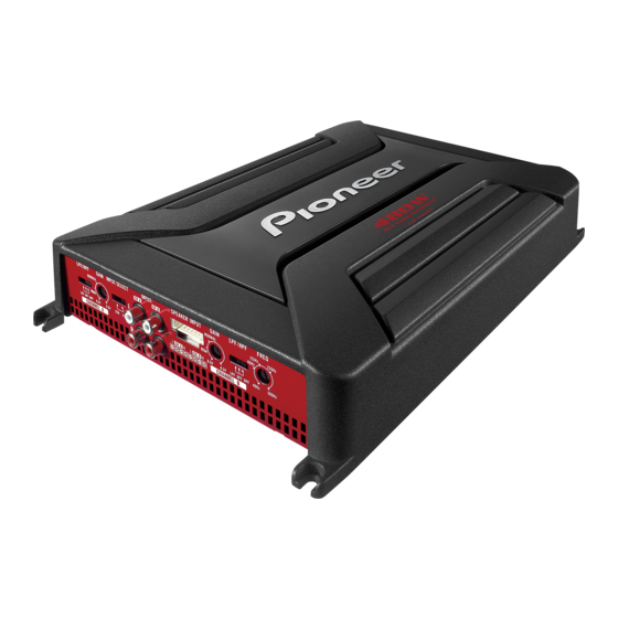
Pioneer GM-A6604 Owner's Manual
Bridgeable four-channel power amplifier
Hide thumbs
Also See for GM-A6604:
- User manual (109 pages) ,
- Owner's manual (57 pages) ,
- Owner's manual (14 pages)
Table of Contents
Quick Links
See also:
User Manual
Table of Contents

Summary of Contents for Pioneer GM-A6604
- Page 1 GM-A6604 GM-A4604...
-
Page 2: Before You Start
This equipment has been tested and found to CANADA comply with the limits for a Class B digital device, Pioneer Electronics of Canada, Inc. pursuant to Part 15 of the FCC Rules. These limits CUSTOMER SATISFACTION DEPARTMENT are designed to provide reasonable protection... -
Page 3: If You Experience Problems
! Do not turn up the volume so high that you please contact your dealer or nearest author- can t hear what s around you. ized Pioneer Service Station. ! Use caution or temporarily discontinue use in potentially hazardous situations. - Page 4 ! Check the connections of the power supply ing functions will operate to protect the product and speakers if the fuse of the separately sold and speaker output. ! The power indicator will turn off and the am- battery wire or the amplifier fuse blows. Deter- mine and resolve the cause, then replace the plifier will shut down in the situations outlined fuse with and identical equivalent.
-
Page 5: Setting The Unit
GAIN (gain) control Front side Adjusting gain controls CHANNEL A (chan- nel A) and CHANNEL B (channel B) helps align the car stereo output to the Pioneer amplifier. Default setting is the NORMAL position. If output remains low, even when the car... -
Page 6: Setting Gain Properly
! Despite correct volume and gain settings, output power will change only slightly. the unit sound still cuts out periodically. In such cases, please contact the nearest authorized Pioneer Service Station. Above illustration shows NORMAL gain set- ting. -
Page 7: Connecting The Units
If the car stereo lacks a system remote control terminal, connect the male terminal to the power term- inal via the ignition switch. Fuse 25 A × 2 (GM-A6604) / 30 A × 1 (GM- A4604) Fuse (30 A) × 2 Grommet... -
Page 8: About Bridged Mode
Speaker channel Power na, antenna cable and tuner. Nominal input: Four-channel output Min. 60 W (GM-A6604) Min. 40 W (GM-A4604) Nominal input: Two-channel output Min. 180 W (GM-A6604) Min. 120 W (GM-A4604) -
Page 9: Connecting The Speakers
The speaker output mode can be four-channel, three-channel (stereo and mono) or two-chan- nel (stereo or mono). Connect the speaker leads based on the mode and the figures shown below. Right Left Speaker out A Speaker out B (Mono) Right Left Speaker out A Speaker out B... -
Page 10: Connections When Using The Rca Input Jack
If only one input plug is used, e.g. when the car stereo has only one output (RCA output), connect the plug to RCA input jack A rather than B. ! Slide INPUT SELECT (input select) switch to 2CH position. Speaker (Mono) RCA input jack A For two-channel output, connect the RCA plugs to the RCA input jack A. -
Page 11: Connecting The Power Terminal
Car Stereo wire damaging it by the cut edges or burrs Speaker output of the hole. After completing all other amplifier connec- White/black: CH A, Left tions, finally connect the battery wire terminal White: CH A, Left of the amplifier to the positive battery term- Gray/black: CH A, Right Gray: CH A, Right... -
Page 12: Connecting The Speaker Output Terminals
Connect the wires to the terminal. Fix the wires securely with the terminal screws. Lug (sold separately) Speaker wire Connect the speaker wires to the speaker output terminals. Fix the speaker wires securely with the term- inal screws. System remote control terminal Ground terminal Power terminal Terminal screws... -
Page 13: Before Installing The Amplifier
! Place all cables away from hot places, such Hole-to-hole distance: 338 mm (13-1/4 in.) as near the heater outlet. (GM-A6604) / 308 mm (12-1/8 in.) (GM- ! The optimal installation location differs de- A4604) pending on the car model. Secure the ampli- Hole-to-hole distance: 196 mm (7-3/4 in.) -
Page 14: Additional Information
Maximum input level / impedance: RCA ........6.5 V / 22 kW GM-A6604 Speaker ......26 V / 16 kW Power source ......14.4 V DC (10.8 V to 15.1 V CEA2006 Specifications allowable) Grounding system ....Negative type Current consumption .... 31 A (at continuous power, 4 W) Average current drawn .. - Page 15 (B ch) Cut off frequency ... 40 Hz to 500 Hz Cut off slope ..... 12 dB/oct High pass filter: (A ch) Cut off frequency ... 80 Hz Cut off slope ..... 12 dB/oct (B ch) Cut off frequency ... 40 Hz to 500 Hz Cut off slope .....
- Page 16 TEL: 1-877-283-5901 TEL: 905-479-4411 Blvd.Manuel Avila Camacho 138 10 piso Col.Lomas de Chapultepec, Mexico, D.F. 11000 TEL: 55-9178-4270 先鋒股份有限公司 台北市內湖區瑞光路407號8樓 ã 2013 PIONEER CORPORATION. 電話: 886-(0)2-2657-3588 All rights reserved. 先鋒電子(香港)有限公司 ã 2013 PIONEER CORPORATION. 香港九龍長沙灣道909號5樓 Tous droits de reproduction et de 電話:...
- Page 18 Within 40 days of receiving your complaint, Pioneer will investigate the dispute and will either: (1) respond to your complaint in writing informing you what action Pioneer will take, and in what time period, to resolve the dispute; or (2) respond to your complaint in writing informing you why it will not take any action.


