
Related Manuals for Yamaha WOLVERINE YFM45FXX


Summary of Contents for Yamaha WOLVERINE YFM45FXX
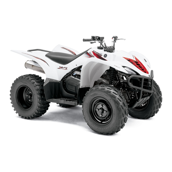
- Page 1 READ THIS MANUAL CAREFULLY! It contains important safety information. OWNER’S MANUAL YFM45FXX WARNING This ATV should not be ridden by anyone under 16 years of age. LIT-11626-21-47 3C2-F8199-12...
- Page 2 EBU17091...
- Page 3 Yamaha experience in the production of fine sporting, touring, and pacesetting racing machines. With the purchase of this Yamaha, you can now appreciate the high degree of craftsmanship and reliability that have made Yamaha a leader in these fields.
- Page 4 EBU17330 IMPORTANT MANUAL INFORMATION EBU17341 FAILURE TO FOLLOW THE WARNINGS CONTAINED IN THIS MANUAL CAN RESULT IN SERIOUS IN- JURY OR DEATH. Particularly important information is distinguished in this manual by the following notations: The Safety Alert Symbol means ATTENTION! BECOME ALERT! YOUR SAFETY IS INVOLVED! Failure to follow WARNING instructions could result in severe injury or death to the ATV operator, a bystander, or a person inspecting or...
- Page 5 EBU17350 IMPORTANT NOTICE EBU17360 Welcome to the Yamaha world of motor sports! This ATV is designed and manufactured for OFF-ROAD use only. It is illegal and unsafe to operate this ATV on any public street, road or highway. This ATV complies with all applicable OFF-ROAD noise level and spark arrester laws and regulations in effect at the time of manufacture.
-
Page 6: Table Of Contents
Speed limiter ..........4-7 EWB00010 WARNING Front brake lever .........4-8 Brake pedal and rear brake lever ....4-9 Indicates a potential hazard that could result in serious injury or death. Drive select lever ........4-9 Fuel tank cap ..........4-10 Fuel ............4-10 Fuel cock ..........4-12 EBU17420 Starter (choke) .........4-13 TABLE OF CONTENTS... - Page 7 Chassis fasteners ........5-9 WHAT TO DO..........7-32 Instruments, lights and switches ....5-9 PERIODIC MAINTENANCE AND MINOR OPERATION ..........6-1 REPAIR ............8-1 Starting a cold engine ........ 6-1 Owner’s manual and tool kit .......8-1 Starting a warm engine ......6-3 Periodic maintenance chart for Operating the drive select lever and the emission control system .....8-3...
- Page 8 Noise regulation ........11-3 Brake light switches ......... 8-45 Maintenance record ........11-4 Checking and lubricating the cables ..8-46 YAMAHA MOTOR CORPORATION, Checking and lubricating the front and U.S.A. ATV LIMITED WARRANTY ..11-5 rear brake levers ........8-46 YAMAHA EXTENDED SERVICE Checking and lubricating the brake (Y.E.S.) ...........11-7...
-
Page 9: Safety Information
EBU17430 SAFETY INFORMATION EBU17513 Never allow a child under age 16 to operate an ATV without adult supervision, and never allow AN ATV IS NOT A TOY AND CAN BE HAZARD- continued use of an ATV by a child if he or she OUS TO OPERATE. - Page 10 Always inspect your ATV each time you use it to Always follow proper procedures for climbing make sure it is in safe operating condition. Al- hills as described in this manual. Check the ter- ways follow the inspection and maintenance rain carefully before you start up any hill.
- Page 11 hill. If you stall or roll backwards, follow the spe- Always be sure there are no obstacles or people cial procedure for braking described in this man- behind you when you operate in reverse. When ual. Dismount on the uphill side or to a side if it is safe to proceed in reverse, go slowly.
- Page 12 EWB00021 HOW TO AVOID THE HAZARD WARNING If you should swallow some gasoline or in- hale a lot of gasoline vapor, or get some gas- POTENTIAL HAZARD oline in your eyes, seek medical help Improper handling of gasoline. immediately. If gasoline spills on your skin, WHAT CAN HAPPEN wash with soap and water.
- Page 13 WHAT CAN HAPPEN Exhaust fumes are poisonous and may cause loss of consciousness and death within a short time. HOW TO AVOID THE HAZARD Always operate your ATV in an area with ad- equate ventilation.
-
Page 14: Location Of The Warning And Specification Labels
EBU17660 LOCATION OF THE WARNING AND SPECIFICATION LABELS... - Page 15 Read and understand all of the labels on your ATV. These labels contain important information for safe and proper operation. Never remove any labels from your ATV. If a label becomes difficult to read or comes off, request a replace- ment label from your Yamaha dealer.
-
Page 17: Description
EBU17680 DESCRIPTION EBU17690 EBU17700 Left view Right view 1. Front shock absorber assembly spring preload adjusting 1. Spark arrester ring 2. Tail/brake light 2. Fuel cock 3. Battery 3. Air filter case 4. Spark plug 4. Fuses 5. Rear brake fluid reservoir 5. -
Page 18: Controls And Instruments
EBU17712 NOTE: Controls and instruments The ATV you have purchased may differ slightly from the figures shown in this manual. 1. Rear brake lever 2. Handlebar switches 3. Starter (choke) 4. Drive select lever 5. Main switch 6. Speedometer unit 7. -
Page 19: Instrument And Control Functions
EBU17720 INSTRUMENT AND CONTROL FUNCTIONS EWB00010 WARNING Indicates a potential hazard that could result in serious injury or death. EBU17760 Main switch The positions of the main switch are as follows: All electrical systems are supplied with power. The headlights and taillight come on when the light 1. -
Page 20: Indicator Lights And Warning Light
NOTE: Indicator lights and warning light If the indicator light flashes under any other circum- stances or the speedometer does not show the speed while riding, have a Yamaha dealer check the speed sensor circuit. EBU17860 Neutral indicator light “... -
Page 21: Speedometer Unit
Start the engine after making sure that the EBU26362 Speedometer unit warning light is out. Continuous use while the warning light is on may cause damage to the engine. EBU26591 On-Command four-wheel-drive indicator “ ” This indicator comes on when the On-Command four-wheel-drive switch is set to the “4WD”... -
Page 22: Handlebar Switches
Odometer and tripmeter modes EBU18061 Handlebar switches Pushing the “SELECT” button switches the display between the odometer mode “ODO” and the trip- meter mode “TRIP” in the following order: ODO → TRIP → ODO To reset the tripmeter, select it by pushing the “SE- LECT”... - Page 23 EBU18100 EBU28210 Start switch “ ” On-Command four-wheel-drive switch Push this switch to crank the engine with the start- “2WD”/“4WD” This ATV is equipped with a switch to change from two-wheel drive to four-wheel drive and vice-versa. ECB00050 CAUTION: Select the appropriate drive according to the ter- See the starting instructions on page 6-1 prior rain and the conditions.
-
Page 24: Throttle Lever
WHAT CAN HAPPEN The ATV handles differently in two-wheel drive than in four-wheel drive in some cir- cumstances. Changing from two-wheel drive to four-wheel drive or from four-wheel drive to two-wheel drive while moving may cause the ATV to unexpectedly handle differently. This could distract the operator and in- crease the risk of losing control and of caus- ing an accident. -
Page 25: Speed Limiter
Check the operation of the throttle lever be- fore you start the engine. If it does not work smoothly, check for the cause. Correct the problem before riding the ATV. Consult a Yamaha dealer if you can’t find or solve the problem yourself. EBU18311 Speed limiter Your ATV was delivered with an adjustable speed limiter. -
Page 26: Front Brake Lever
HOW TO AVOID THE HAZARD Do not turn the adjusting screw out more than 12 mm (0.47 in). Always make sure the throttle lever free play is adjusted to 3.0–5.0 mm (0.12–0.20 in). (See page 8-38.) EBU18391 Front brake lever The front brake lever is located on the right handle- bar. -
Page 27: Brake Pedal And Rear Brake Lever
EBU18442 Brake pedal and rear brake lever The brake pedal is located on the right side of the ATV and the rear brake lever is located on the left handlebar. To apply the rear brake, push down on the brake pedal or pull the brake lever toward the handlebar grip. -
Page 28: Fuel Tank Cap
1. Drive select lever 1. Fuel tank cap EBU18720 EBU18730 Fuel tank cap Fuel Remove the fuel tank cap by turning it counter- Make sure that there is sufficient fuel in the tank. clockwise. Fill the fuel tank to the bottom of the filler tube as shown. - Page 29 Your Yamaha engine has been designed to use regular unleaded gasoline with a pump octane number [(R+M)/2] of 86 or higher, or a research oc- tane number of 91 or higher.
-
Page 30: Fuel Cock
EWB00270 WARNING POTENTIAL HAZARD Improper care when refueling. WHAT CAN HAPPEN Fuel can spill, which can cause a fire and se- vere injury. Fuel expands when it heats up. If the fuel tank is overfilled, fuel could spill out due to heat from the engine or the sun. -
Page 31: Starter (Choke)
1. Arrow mark positioned over “ON” 1. Arrow mark positioned over “RES” With the fuel cock lever in this position, fuel flows This indicates reserve. With the fuel cock lever in to the carburetor. Turn the fuel cock lever to this this position, the fuel reserve is made available. -
Page 32: Seat
Move the starter (choke) in direction (b) to turn off the starter (choke). See the “Starting a cold engine” section on page 6-1 for proper operation. 1. Seat 1. Starter (choke) “ ” EBU26981 Seat To remove the seat Push the seat lock lever backward and pull up the seat at the rear. -
Page 33: Storage Compartment
To install the seat When storing any documents in the storage com- Fit the slot in the seat onto the projection on the partment, be sure to wrap them in a plastic bag so front cowling, insert the projections on the front of that they will not get wet. -
Page 34: Adjusting The Front Shock Absorber Assemblies
1. Spring preload adjusting ring 2. Position indicator NOTE: A special wrench can be obtained at a Yamaha 1. Storage compartment drain plug dealer to make this adjustment. EBU18980 Adjusting the front shock absorber as-... -
Page 35: Adjusting The Rear Shock Absorber Assembly
WHAT CAN HAPPEN Uneven adjustment can cause poor handling and loss of stability, which could lead to an accident. HOW TO AVOID THE HAZARD Always adjust the shock absorber assem- blies on the left and right side to the same setting. - Page 36 1. Spring preload adjusting ring 1. Special wrench 2. Position indicator Spring preload setting: Minimum (soft): NOTE: A special wrench can be obtained at a Yamaha dealer to make this adjustment. Standard: Maximum (hard): EWB00010 WARNING Indicates a potential hazard that could result in serious injury or death.
-
Page 37: Pre-Operation Checks
Manual. NOTE: The maintenance of some items in the table has to be performed by a Yamaha dealer. Refer to the periodic maintenance charts on page 8-3 to determine which service should be performed by a Yamaha dealer. ITEM... - Page 38 5-4, 8-26 • Check cooling system for leakage. Correct if necessary. • Check operation. If soft or spongy, have Yamaha dealer bleed hy- draulic system. • Check brake pads for wear, and replace if necessary. Front brake 5-5, 8-39, 8-40, 8-42 •...
- Page 39 ITEM ROUTINE PAGE • Make sure that operation is smooth. Lubricate lever pivoting points if Brake levers 8-46 necessary. Axle boots • Check for cracks or damage, and replace if necessary. 8-44 Chassis fasteners • Make sure that all nuts, bolts and screws are properly tightened. Instruments, lights and •...
-
Page 40: Fuel
EBU19530 EBU19590 Fuel Final gear oil Make sure that there is sufficient fuel in the tank. Make sure that the final gear oil is at the specified (See page 4-10.) level. Add oil as necessary. (See page 8-22.) EWB00500 WARNING EBU19600 Differential gear oil POTENTIAL HAZARD... -
Page 41: Front And Rear Brakes
If there is any leakage, the brake system should be Check that there is no free play in the front brake checked by a Yamaha dealer. lever. If there is free play, have a Yamaha dealer check the brake system. Brake operation... -
Page 42: Throttle Lever
HOW TO AVOID THE HAZARD vided in this manual, have a Yamaha dealer The tires listed below have been approved check for the cause. by Yamaha Motor Manufacturing Corpora- tion of America for this model. -
Page 43: Measuring The Tire Pressure
Rear: Tire pressure below the minimum speci- Manufacturer/model: fied could cause the tire to dislodge from MAXXIS/M938 the rim under severe riding conditions. Size: Minimum tire pressure: AT23 x 10R12 Front: Type: 37.0 kPa (5.3 psi) (0.370 kgf/cm²) Tubeless Rear: The tires should be set to the recommend- 37.0 kPa (5.3 psi) (0.370 kgf/cm²) ed pressure:... -
Page 44: Specifications
Recommended pressure: NOTE: Front The low-pressure tire gauge is included as stan- 40.0 kPa (5.8 psi) (0.400 kgf/cm²) dard equipment. Make two measurements of the Rear tire pressure and use the second reading. Dust or 40.0 kPa (5.8 psi) (0.400 kgf/cm²) dirt in the gauge could cause the first reading to be Minimum: incorrect. -
Page 45: Chassis Fasteners
1. Tire wear limit EBU19840 Chassis fasteners Make sure that all nuts, bolts and screws are prop- erly tightened. EBU19850 Instruments, lights and switches Check that all instruments, lights and switches are working properly. Correct if necessary. -
Page 46: Operation
Read the Owner’s Manual carefully. If there is prior to operating the engine for the first time. a control or function you do not understand, ask your Yamaha dealer. 1. Turn the fuel cock to “ON”. 2. Turn the main switch to “ON” and the engine stop switch to “... - Page 47 3. Shift the drive select lever into the neutral or Ambient temp./starter (choke) position park position. The corresponding indicator light should come on, if it does not come on, have a Yamaha dealer check the electrical cir- cuit. NOTE: The engine can be started under the following con-...
-
Page 48: Starting A Warm Engine
7. If the engine is started with the starter (choke) EBU20450 Operating the drive select lever and in position (1), the starter (choke) should be driving in reverse returned to position (2) to warm up the engine. ECB00170 If the engine is started with the starter (choke) CAUTION: in position (2), keep the starter (choke) in this Before shifting, stop the ATV, otherwise the... - Page 49 NOTE: should come on. If the indicator light does not The drive select lever cannot be shifted into or from come on, have a Yamaha dealer check the elec- reverse or park without applying the brake pedal. trical circuit. 1. Bring the ATV to a complete stop.
-
Page 50: Engine Break-In
Due to the synchronizing mechanism in the en- For ATVs not equipped with an odometer or gine, the indicator light may not come on until the hour meter, follow the figures given in hours. ATV starts moving. There is never a more important period in the life of 4. -
Page 51: Parking
If any engine trouble should occur during the transversely across the incline, stop the en- engine break-in period, immediately have a Yamaha dealer check the ATV. gine, shift the drive select lever to the park position, and then block the front and rear wheels with rocks or other objects. -
Page 52: Accessories And Loading
However, er, you must use common sense and good it is not possible for Yamaha to test all non- judgment as the stability and handling of an ATV Yamaha accessories, nor control over their qual- can be changed. - Page 53 If you are carrying cargo and towing a trailer, in- EWB00750 WARNING clude the tongue weight in the maximum ATV load limit. POTENTIAL HAZARD Load cargo on the carriers as close to the center Overloading this ATV or carrying or towing of the ATV as possible.
-
Page 54: Riding Your Atv
EBU21131 RIDING YOUR ATV... -
Page 55: Getting To Know Your Atv
EWB00010 WARNING Indicates a potential hazard that could result in serious injury or death. EBU26562 GETTING TO KNOW YOUR ATV This ATV is intended for recreational use by expe- rienced operators only. Even if you are an experi- enced operator of all other all terrain ATVs or motorcycles, riding the ATV requires special skills acquired through practice. -
Page 56: Ride With Care And Good Judgement
Beginners should get training from a certified in- course offered by Yamaha. They should then structor. regularly practice the skills learned in the Become familiar with this ATV at slow speeds first, course and the operating techniques de- even if you are an experienced operator. - Page 57 WHAT CAN HAPPEN WHAT CAN HAPPEN Use by children of ATVs that are not recom- Greatly reduces your ability to balance and mended for their age can lead to severe inju- control this ATV. Could cause an accident, ry or death of the child. resulting in harm to you and/or your passen- HOW TO AVOID THE HAZARD ger.
- Page 58 Apparel EWB00920 WARNING POTENTIAL HAZARD Operating this ATV without wearing an ap- proved motorcycle helmet, eye protection and protective clothing. WHAT CAN HAPPEN Operating without an approved motorcycle helmet increases your chances of a severe head injury or death in the event of an acci- dent.
- Page 59 HOW TO AVOID THE HAZARD Always wear an approved motorcycle helmet that fits properly. You should also wear: eye protection (goggles or face shield) gloves boots long-sleeved shirt or jacket long pants 1. Protective clothing 2. Goggles 3. Gloves 4. Boots 5.
- Page 60 Do not operate after consuming alcohol or HOW TO AVOID THE HAZARD drugs. Never consume alcohol or drugs before or The operator’s performance capability is reduced while driving this ATV. by the influence of alcohol or drugs. Pre-operation checks Always perform the pre-operation checks listed on page 5-1 before riding for proper care of the ATV and to ensure safety.
- Page 61 EWB00950 Do not operate at speeds too fast for your skills WARNING or the conditions. EWB00960 POTENTIAL HAZARD WARNING Operating this ATV with improper tires, or with improper or uneven tire pressure. POTENTIAL HAZARD WHAT CAN HAPPEN Operating this ATV at speeds too fast for Use of improper tires on this ATV, or opera- your skills or the conditions.
- Page 62 Speed limiter Loading and accessories For riders less experienced with this model, the As originally equipped, this ATV is not designed to throttle lever housing is equipped with a speed lim- carry cargo or tow a trailer. If you choose to add ac- iter.
- Page 63 HOW TO AVOID THE HAZARD Never exceed the stated load capacity for this ATV. Cargo should be properly distributed and se- curely attached. Reduce speed when carrying cargo or pull- ing a trailer. Allow greater distance for brak- ing. Always follow the instructions in your Own- er’s Manual for carrying cargo or pulling a trailer.
- Page 64 During operation WHAT CAN HAPPEN Always keep your feet on the footboards during op- Removing even one hand or foot can reduce eration, otherwise they may contact the rear your ability to control the ATV or could wheels. cause you to lose your balance and fall off of the ATV.
- Page 65 Never modify this ATV through improper in- stallation or use of accessories. All parts and accessories added to this ATV should be genuine Yamaha or equivalent compo- nents designed for use on this ATV and should be installed and used according to instructions.
-
Page 66: Be Careful Where You Ride
Exhaust system The exhaust system on the ATV is very hot during and following operation. To prevent burns, avoid touching the exhaust system. Park the ATV in a place where pedestrians or children are not likely to touch it. EWB01010 WARNING POTENTIAL HAZARD Hot exhaust system. - Page 67 HOW TO AVOID THE HAZARD EWB01030 WARNING Always avoid paved surfaces, including sidewalks, driveways, parking lots and POTENTIAL HAZARD streets. Operating this ATV on public streets, roads or highways. WHAT CAN HAPPEN You can collide with another vehicle. HOW TO AVOID THE HAZARD Never operate this ATV on any public street, road or highway, even a dirt or gravel one.
- Page 68 Know the terrain where you ride. Ride cautiously in unfamiliar areas. Stay alert for holes, rocks, or roots in the terrain, and other hidden hazards which may cause the ATV to upset. EWB01040 WARNING POTENTIAL HAZARD Failure to use extra care when operating this ATV on unfamiliar terrain.
- Page 69 HOW TO AVOID THE HAZARD Do not operate on excessively rough, slip- pery or loose terrain until you have learned and practiced the skills necessary to control the ATV on such terrain. Always be especial- ly cautious on these kinds of terrain. EWB01060 WARNING POTENTIAL HAZARD...
-
Page 70: Turning Your Atv
Do not ride in areas posted “no trespassing”. be hot when riding and afterwards; do not allow Do not ride on private property without getting per- skin or clothing to come in contact with these com- mission. ponents. With the engine idling, return the starter (choke) to the closed position, and shift the drive select lever into the forward position. - Page 71 used to allow the ATV to make turns quickly and easily. It is essential that this skill be learned first at low speed. EWB01080 WARNING POTENTIAL HAZARD Turning improperly. WHAT CAN HAPPEN ATV could go out of control, causing a colli- sion or overturn.
-
Page 72: Climbing Uphill
Improper riding procedures such as abrupt throttle WHAT CAN HAPPEN changes, excessive braking, incorrect body move- The ATV can overturn more easily on ex- ments, or too much speed for the sharpness of the tremely steep hills than on level surfaces or turn may cause the ATV to tip. - Page 73 HOW TO AVOID THE HAZARD Always follow proper procedures for climb- ing hills as described in this Owner’s Manu- Always check the terrain carefully before you start up any hill. Never climb hills with excessively slippery or loose surfaces. Shift your weight forward. Never open the throttle suddenly.
- Page 74 If you are climbing a hill and you find that you have When crossing the side of a hill: not properly judged your ability to make it to the Always follow proper procedures as de- top, you should turn the ATV around while you still scribed in the Owner’s Manual.
- Page 75 If you start to roll backwards, DO NOT apply either If you begin rolling backwards: brake abruptly. If you are in 2WD, apply only the Keep weight uphill. front brake. If you are in 4WD, because all wheels 2WD: Never apply the rear brake while roll- are interconnected by the drive train, applying ei- ing backwards.
-
Page 76: Riding Downhill
RIDING DOWNHILL Whenever possible, ride your ATV straight down- When riding your ATV downhill, shift your weight hill. Avoid sharp angles which could allow the ATV as far to the rear and uphill side of the ATV as pos- to tip or roll over. Carefully choose your path and sible. - Page 77 7-24...
-
Page 78: Crossing A Slope
CROSSING A SLOPE HOW TO AVOID THE HAZARD Traversing a sloping surface on your ATV requires Never attempt to turn the ATV around on any you to properly position your weight to maintain hill until you have mastered the turning tech- proper balance. - Page 79 7-26...
-
Page 80: Crossing Through Shallow Water
CROSSING THROUGH SHALLOW WATER The ATV can be used to cross slow moving, shal- low water of up to a maximum of 35 cm (14 in) in depth. Before entering the water, choose your path carefully. Enter where there is no sharp drop off, and avoid rocks or other obstacles which may be slippery or upset the ATV. - Page 81 1. Air filter case check hose ECB00730 CAUTION: After riding your ATV in water, be sure to drain the trapped water by removing the check hose at the bottom of the air filter case, the V-belt cooling duct check hose, the drive select lever box check hose and the storage compartment drain plugs.
-
Page 82: Riding Over Rough Terrain
1. Drive select lever box check hose 1. V-belt case drain plug RIDING OVER ROUGH TERRAIN Riding over rough terrain should be done with cau- tion. Look out for obstacles which could cause damage to the ATV or could lead to an upset or ac- cident. -
Page 83: Sliding And Skidding
WHAT CAN HAPPEN Could cause loss of control or a collision. Could cause the ATV to overturn. HOW TO AVOID THE HAZARD Before operating in a new area, check for ob- stacles. Never attempt to ride over large obstacles, such as large rocks or fallen trees. When you go over obstacles, always follow proper procedures as described in the Owner’s Manual. -
Page 84: What To Do If
If the rear wheels of your ATV start to slide side- EWB01170 WARNING ways, control can usually be regained (if there is room to do so) by steering in the direction of the POTENTIAL HAZARD slide. Applying the brakes or accelerating is not Skidding or sliding improperly. -
Page 85: What To Do
WHAT TO DO... If your ATV is traversing a sloping surface: If your ATV doesn’t turn when you want it to: Be sure to ride with your weight positioned to- Bring the ATV to a stop and practice the turning wards the uphill side of the ATV to maintain maneuvers again. -
Page 86: Periodic Maintenance And Minor Repair
Safety is an obligation of the owner. Periodic in- nance unless otherwise specified. Have a spection, adjustment and lubrication will keep your Yamaha dealer perform the service if you are ATV in the safest and best operating condition not familiar with maintenance work. - Page 87 Yamaha ATV dealer. additional tools such as a torque wrench may be necessary to perform certain maintenance work correctly. NOTE: If you do not have the tools or experience required for a particular job, have a Yamaha dealer perform it for you.
-
Page 88: Periodic Maintenance Chart For The Emission Control System
However, keep in mind that if the ATV isn’t used for a long period of time, the month maintenance intervals should be followed. Items marked with an asterisk should be performed by a Yamaha dealer as they require special tools, data and technical skills. - Page 89 INITIAL EVERY month Whichev- CHECK OR MAINTENANCE ITEM er comes 1300 2500 2500 5000 first (mi) (200) (800) (1600) (1600) (3200) hours • Check for leakage and replace gasket(s) if neces- sary. √ √ √ Exhaust system • Check for looseness and tighten all screw clamps and joints if necessary.
-
Page 90: General Maintenance And Lubrication Chart
EBU21864 General maintenance and lubrication chart INITIAL EVERY month Whichev- CHECK OR MAINTENANCE ITEM er comes 1300 2500 2500 5000 first (mi) (200) (800) (1600) (1600) (3200) hours Every 20–40 hours (more often in wet or Air filter element • Clean and replace if necessary. dusty areas) •... - Page 91 INITIAL EVERY month Whichev- CHECK OR MAINTENANCE ITEM er comes 1300 2500 2500 5000 first (mi) (200) (800) (1600) (1600) (3200) hours √ √ √ Swingarm • Check for excessive play, and correct if necessary. • Check for wear, cracks or other damage, and re- √...
- Page 92 INITIAL EVERY month Whichev- CHECK OR MAINTENANCE ITEM er comes 1300 2500 2500 5000 first (mi) (200) (800) (1600) (1600) (3200) hours • Change. √ √ Final gear oil • Check ATV for oil leakage, and correct if neces- sary. •...
- Page 93 Hydraulic brake service • Regularly check and, if necessary, correct the brake fluid level. • Every two years replace the internal components of the brake master cylinders and calipers, and change the brake fluid. • Replace the brake hoses every four years and if cracked or damaged.
-
Page 94: Removing And Installing Cowlings And Panels
EWB00010 WARNING Indicates a potential hazard that could result in serious injury or death. EBU26401 Removing and installing cowlings and panels The cowlings and panels shown need to be re- moved to perform some of the maintenance jobs described in this chapter. Refer to this section each time a cowling or panel needs to be removed and 1. - Page 95 1. Speedometer unit coupler 1. Bolt (left side) 4. Remove cowling A by removing the bolts, nuts and washers. 1. Bolt (right side) 1. Bolt 8-10...
- Page 96 To install the cowling 3. Pull off the handlebar cover. 1. Connect the speedometer unit couplers. ECB00740 CAUTION: 2. Install cowling A by installing the bolts, nuts and washers. Do not disconnect the main switch coupler. 3. Install panel B. 4.
- Page 97 5. Remove the cowling by removing the bolts. 1. Bolt (right side) 1. Bolt 6. Install the fuel tank cap by turning it clockwise. To install the cowling 1. Remove the fuel tank cap by turning it coun- terclockwise. 2. Install the cowling by installing the bolts. 3.
- Page 98 EBU26412 Panel B To remove the panel Pull outward on the areas shown. Panel A To remove the panel Remove the bolt, and then take the panel off. 1. Panel B To install the panel Insert the projections on the panel into the slots in 1.
- Page 99 1. Projection 1. Panel C 2. Slot 2. Bolt To install the panel Panel C Place the panel in the original position and install To remove the panel the bolts. Remove the bolts, and then take the panel off. Panel D To remove the panel Pull outward on the areas shown.
-
Page 100: Checking The Spark Plug
EBU23211 Checking the spark plug The spark plug is an important engine component, which is easy to check. Since heat and deposits will cause any spark plug to slowly erode, the spark plug should be removed and checked in accor- dance with the periodic maintenance and lubrica- tion chart. - Page 101 (the ideal color when the ATV is ridden normally). NOTE: If the spark plug shows a distinctly different color, the engine could be operating improperly. Do not attempt to diagnose such problems yourself. In- stead, have a Yamaha dealer check the ATV. 8-16...
-
Page 102: Engine Oil And Oil Filter Cartridge
NOTE: If a torque wrench is not available when installing a spark plug, a good estimate of the correct torque is 1/4–1/2 turn past finger tight. However, the spark plug should be tightened to the specified torque as soon as possible. 4. - Page 103 4. Remove the engine oil filler cap, and then wipe the dipstick off with a clean rag. 1. Dipstick 2. Maximum level mark 3. Minimum level mark 1. Engine oil filler cap 5. Insert the dipstick into the filler hole (without NOTE: screwing it in), and then remove it again to The engine oil should be between the minimum...
- Page 104 To change the engine oil (with or without oil fil- NOTE: ter cartridge replacement) Skip steps 6–10 if the oil filter cartridge is not being 1. Place the ATV on a level surface. replaced. 2. Remove panel D. (See page 8-9.) 6.
- Page 105 1. Oil filter wrench 1. O-ring NOTE: NOTE: An oil filter wrench is available at a nearby Yamaha Make sure that the O-ring is properly seated. dealer. 9. Install the new oil filter cartridge with an oil fil- 8. Apply a thin coat of engine oil to the O-ring of ter wrench, and then tighten it to the specified the new oil filter cartridge.
- Page 106 12. Add the specified amount of the recommend- ed engine oil, and then install and tighten the engine oil filler cap. Recommended oil: See page 10-1. Oil quantity: Without oil filter cartridge replacement: 2.30 L (2.43 US qt) (2.02 Imp.qt) With oil filter cartridge replacement: 2.40 L (2.54 US qt) (2.11 Imp.qt) 1.
-
Page 107: Final Gear Oil
The final gear case must be checked for oil leak- age before each ride. If any leakage is found, have a Yamaha dealer check and repair the ATV. In ad- dition, the final gear oil level must be checked and 1. -
Page 108: To Change Final Gear Oil
Tightening torque: Final gear oil filler bolt: 23 Nm (2.3 m·kgf, 17 ft·lbf) To change the final gear oil 1. Remove the final gear case guard by remov- ing the bolts. 1. Final gear oil drain bolt 5. Install the drain bolt, and then tighten it to the specified torque. -
Page 109: Changing The Differential Gear Oil
The differential gear case must be checked for oil leakage before each ride. If any leakage is found, ECB00420 have a Yamaha dealer check and repair the ATV. CAUTION: In addition, the differential gear oil must be Be sure no foreign material enters the final changed as follows at the intervals specified in the gear case. - Page 110 3. Remove the differential gear oil filler bolt and the differential gear oil drain bolt to drain the oil from the differential gear case. 1. Differential gear oil drain bolt 4. Install the drain bolt, and then tighten it to the specified torque.
-
Page 111: Coolant
The differential gear case capacity is greater EBU23470 Coolant than the recommended oil quantity, therefore The coolant level should be checked before each the oil level cannot be accurately checked from ride. In addition, the coolant must be changed at the oil filler hole. - Page 112 1. Maximum level mark 1. Coolant reservoir cap 2. Minimum level mark Coolant reservoir capacity (up to the maximum 3. If the coolant is at or below the minimum level level mark): mark, remove the reservoir cap, add coolant 0.25 L (0.26 US qt) (0.22 Imp.qt) or distilled water to the maximum level mark, and then install the reservoir cap.
- Page 113 If water has been added to the coolant, have HOW TO AVOID THE HAZARD a Yamaha dealer check the antifreeze con- Wait for the engine to cool before removing tent of the coolant as soon as possible, oth- the radiator cap. Always place a thick rag erwise the effectiveness of the coolant will over the cap.
- Page 114 6. Remove the coolant reservoir cap. 7. Disconnect the hose on the coolant reservoir side, and then drain the coolant from the cool- ant reservoir. 1. Trough 4. Remove cowling A. (See page 8-9.) 5. Remove the radiator cap. 1. Coolant reservoir hose 8.
- Page 115 Coolant reservoir capacity (up to the maxi- leakage. mum level mark): 0.25 L (0.26 US qt) (0.22 Imp.qt) NOTE: If any leakage is found, have a Yamaha dealer ECB00401 check the cooling system. CAUTION: 16. Install the cowling. If coolant is not available, use distilled water 17.
-
Page 116: Cleaning The Air Filter Element
EBU23631 2. Remove the air filter case cover by unhooking Cleaning the air filter element the holders. The air filter element should be cleaned at the in- tervals specified in the periodic maintenance and lubrication chart. Clean the air filter element more frequently if you are riding in unusually wet or dusty areas. - Page 117 1. Air filter element 1. Air filter element frame 2. Sponge material 4. Pull off the lock plate, and then remove the 3. Air filter element lock plate sponge material from the air filter element 5. Wash the sponge material gently but thor- frame.
- Page 118 7. Check the sponge material and replace it if 6. Squeeze the excess solvent out of the sponge damaged. material and let it dry. 8. Apply Yamaha foam air filter oil or other qual- ECB00440 ity foam air filter oil to the sponge material. CAUTION:...
-
Page 119: Cleaning The Spark Arrester
EBU26451 NOTE: Cleaning the spark arrester The air filter element should be cleaned every 20– Be sure the exhaust pipe and muffler are cool be- 40 hours. It should be cleaned and lubricated more fore cleaning the spark arrester. often if the ATV is operated in extremely dusty ar- 1. -
Page 120: V-Belt Cooling Duct Check Hose
EWB01910 WARNING POTENTIAL HAZARD Improper cleaning of the spark arrester. Hot exhaust system. WHAT CAN HAPPEN Could injure the eyes. Could cause burns. Could cause carbon monoxide poisoning, possibly leading to death. Could start a fire. 1. Tailpipe HOW TO AVOID THE HAZARD 2. -
Page 121: V-Belt Case Drain Plug
If water drains from the V-belt case after removing most carburetor adjustments should be left to a the plug, have a Yamaha dealer check the ATV as Yamaha dealer, who has the necessary profes- the water may affect other engine parts. -
Page 122: Adjusting The Engine Idling Speed
NOTE: NOTE: If the specified idling speed cannot be obtained as The engine is warm when it quickly responds to the described above, have a Yamaha dealer make the throttle. adjustment. 2. Attach the tachometer to the spark plug lead. -
Page 123: Adjusting The Throttle Cable Free Play
The valve clearance changes with use, resulting in bolt in direction (b). improper air-fuel mixture and/or engine noise. To prevent this from occurring, the valve clearance must be adjusted by a Yamaha dealer at the inter- vals specified in the periodic maintenance and lu- brication chart. 8-38... -
Page 124: Adjusting The Drive Select Lever Safety System Cable
1.0 mm Each rear brake pad is provided with wear indica- (0.04 in), have a Yamaha dealer replace the brake tor grooves, which allow you to check the brake pads as a set. -
Page 125: Checking The Brake Fluid Level
brake pads and/or brake system leakage. If the brake fluid level is low, be sure to check the brake pads for wear and the brake system for leakage. Front brake 1. Wear indicator groove NOTE: The wheels need to be removed to check the brake pads. -
Page 126: Changing The Brake Fluid
To check the rear brake fluid level, remove cowling EBU24290 Changing the brake fluid B. (See page 8-9.) Have a Yamaha dealer change the brake fluid at Observe these precautions: the intervals specified in the NOTE after the peri- When checking the fluid level, make sure that odic maintenance and lubrication chart. -
Page 127: Checking The Front Brake Lever Free Play
After servicing: free play of zero mm (zero in) as shown. If the free Make sure the brakes operate smoothly play is incorrect, have a Yamaha dealer check the and that the free play is correct. brake system. Make sure the brakes do not drag. - Page 128 2. Brake lever free play adjusting bolt 3. Tighten the locknut. If the correct free play cannot be obtained, have a Yamaha dealer adjust it. NOTE: When adjusting the rear brake lever free play: Be sure not to step on the brake pedal.
-
Page 129: Axle Boots
Make sure the brakes operate smoothly footboard bracket. If the brake pedal position is in- and that the free play is correct. correct, have a Yamaha dealer adjust it. Make sure the brakes do not drag. Make sure the brakes are not spongy. All air must be bled from the brake system. -
Page 130: Brake Light Switches
The brake light switch for the brake pedal can be adjusted as follows, but the other brake light switches should be adjusted by a Yamaha dealer. 1. Brake light switch 1. Remove panel A. (See page 8-9.) 2. Brake light switch adjusting nut 3. -
Page 131: Checking And Lubricating The Cables
If a cable is damaged or does not move pivots should be lubricated if necessary. smoothly, have a Yamaha dealer check or replace Recommended lubricants: Front brake lever: Recommended lubricant:... -
Page 132: Checking And Lubricating The Brake Pedal
Yamaha dealer check the wheel hub bear- NOTE: ings. To access the brake pedal pivot, remove panel A. - Page 133 Ventilate when charg- ing or using in a closed space. To charge the battery Have a Yamaha dealer charge the battery as soon as possible if it seems to have discharged. Keep in mind that the battery tends to discharge more quickly if the ATV is equipped with optional electri- cal accessories.
- Page 134 If you do not have 2. Make sure to properly connect the battery access to a constant-voltage battery charg- leads to the battery terminals. er, have a Yamaha dealer charge your bat- tery. 1. Positive battery lead (red) 2. Negative battery lead (black)
-
Page 135: Replacing A Fuse
EBU25313 Replacing a fuse 1. Headlight fuse 2. Ignition fuse 1. Main fuse 3. Auxiliary DC jack fuse (for optional auxiliary DC jack) 2. Spare main fuse 4. Four-wheel-drive motor fuse 3. Fuse box 5. Signaling system fuse 6. Backup fuse (for odometer and tripmeter) 7. -
Page 136: Replacing A Headlight Bulb
15.0 A circuits to check if the devices operate. Ignition fuse: 4. If the fuse immediately blows again, have a 10.0 A Yamaha dealer check the electrical system. Four-wheel-drive motor fuse: 3.0 A EBU25531 Replacing a headlight bulb Signaling system fuse: 10.0 A... - Page 137 3. Remove the defective bulb from the headlight unit by pulling it out. EWB02180 WARNING POTENTIAL HAZARD A headlight bulb is hot when it is on and im- mediately after it is turned off. WHAT CAN HAPPEN You can be burned, or a fire could start if the bulb touches something flammable.
-
Page 138: Adjusting A Headlight Beam
5. Install the headlight bulb holder by aligning the ECB00690 projections with the holes in the headlight unit, CAUTION: pushing it inward, and turning it clockwise until It is advisable to have a Yamaha dealer make it stops. this adjustment. 8-53... -
Page 139: Replacing The Tail/Brake Light Bulb
To raise a headlight beam, turn the adjusting bolt in direction (a). To lower a headlight beam, turn the adjusting bolt in direction (b). 1. Screw 2. Remove the defective bulb by pushing it in and turning it counterclockwise. 1. Headlight beam adjusting bolt EBU25600 Replacing the tail/brake light bulb If the tail/brake light bulb burns out, replace it as... -
Page 140: Removing A Wheel
3. Insert a new bulb into the socket, push it in, 4. Remove the wheel. and then turn it clockwise until it stops. EBU25700 4. Install the lens by installing the screws. Installing a wheel ECB00700 1. Install the wheel and the nuts. CAUTION: Do not overtighten the screws, otherwise the NOTE:... -
Page 141: Troubleshooting
The following troubleshooting charts represent quick and easy procedures for checking these vital systems yourself. However, should your ATV re- quire any repair, take it to a Yamaha dealer, whose skilled technicians have the necessary tools, expe- 1. Tapered nut rience, and know-how to service the ATV properly. - Page 142 EWB02260 WARNING POTENTIAL HAZARD Checking the fuel system while smoking or near an open flame. WHAT CAN HAPPEN Fuel can ignite or explode, causing severe injury or property damage. HOW TO AVOID THE HAZARD Do not smoke when checking the fuel sys- tem.
-
Page 143: Troubleshooting Charts
Remove the spark plug and check the electrodes. The engine does not start. Have a Yamaha dealer check the ATV. Check the battery. 4. Battery The engine turns over The battery is good. - Page 144 Start the engine. If the engine overheats again, have a The coolant level Yamaha dealer check and repair the cooling system. is OK. NOTE: If coolant is not available, tap water can be temporarily used instead, provided that it is changed to the rec- ommended coolant as soon as possible.
-
Page 145: Cleaning And Storage
EBU25860 CLEANING AND STORAGE EBU25870 ed from improper high-pressure detergent Cleaning applications such as those available in coin- Frequent, thorough cleaning of your ATV will not operated car washers. only enhance its appearance but will improve its 4. Once most of the dirt has been hosed off, general performance and extend the useful life of wash all surfaces with warm water and mild, many components. -
Page 146: Storage
EWB02300 To prevent corrosion, avoid damp cellars, WARNING stables (because of the presence of ammo- nia) and areas where strong chemicals are POTENTIAL HAZARD stored. Operation with wet brakes after washing. WHAT CAN HAPPEN Wet brakes may have reduced stopping abil- Long-term ity, increasing the chance of an accident. - Page 147 b. Pour a teaspoonful of engine oil into the sively cold or warm place [less than 0 °C (30 spark plug bore. °F) or more than 30 °C (90 °F)]. For more in- c. Install the spark plug cap onto the spark formation on storing the battery, see page plug, and then place the spark plug on the 8-47.
-
Page 148: Specifications
EBU25960 SPECIFICATIONS Dimensions: Compression ratio: 10.00 :1 Overall length: Starting system: 1978 mm (77.9 in) Electric starter Overall width: Lubrication system: 1063 mm (41.9 in) Wet sump Overall height: Engine oil: 1095 mm (43.1 in) Seat height: Type: 840 mm (33.1 in) YAMALUBE 4, SAE5W30 or SAE10W30 or SAE20W40 Wheelbase: 1233 mm (48.5 in) - Page 149 With oil filter cartridge replacement: Type x quantity: 2.40 L (2.54 US qt) (2.11 Imp.qt) BSR33 x 1 Final gear oil: Spark plug (s): Type: Manufacturer/model: SAE80 API GL-4 Hypoid gear oil NGK/DR8EA Quantity: Spark plug gap: 0.23 L (0.24 US qt) (0.20 Imp.qt) 0.6–0.7 mm (0.024–0.028 in) Differential gear oil: Clutch:...
- Page 150 Trail: Maximum: 19.3 mm (0.76 in) Front: Front tire: 43.0 kPa (6.2 psi) (0.430 kgf/cm²) Rear: Type: 43.0 kPa (6.2 psi) (0.430 kgf/cm²) Tubeless Front wheel: Size: AT23 x 8R12 Wheel type: Manufacturer/model: Panel wheel MAXXIS/M937 Rim size: Rear tire: 12 x 6.0AT Rear wheel: Type:...
- Page 151 Front suspension: Tail/brake light: 12 V, 5.0/21.0 W × 1 Type: Neutral indicator light: Double wishbone Spring/shock absorber type: Reverse indicator light: Coil spring/oil damper Wheel travel: Coolant temperature warning light: 160 mm (6.3 in) Rear suspension: Park indicator light: Type: Swingarm On-Command four-wheel-drive indicator:...
-
Page 152: Consumer Information
Yamaha dealer or for ref- erence in case the ATV is stolen. KEY IDENTIFICATION NUMBER: VEHICLE IDENTIFICATION NUMBER: 1. - Page 153 EBU26050 Model label The model label is affixed at the location in the il- lustration. Record the information on this label in the space provided. This information will be need- ed when ordering spare parts from a Yamaha deal- 11-2...
-
Page 154: Noise Regulation
EBU26060 Noise regulation TAMPERING WITH NOISE CONTROL SYSTEM PROHIBITED: Federal law prohibits the following acts or the causing thereof: (1) The removal or rendering inoperative by any person other than for purposes of maintenance, repair, or replacement of any device or element of de- sign incorporated into any new vehicle for the purpose of noise control prior to its sale or delivery to the ul- timate purchaser or while it is in use or (2) the use of the vehicle after such device or element of design has been removed or rendered inoperative by any person. -
Page 155: Maintenance Record
EBU26080 Maintenance record Copies of work orders and/or receipts for parts you purchase and install will be required to document main- tenance done in accordance with the warranty. The chart below is printed only as a reminder to you that the maintenance work is required. -
Page 156: Yamaha Motor Corporation, U.s.a. Atv Limited Warranty
(6) months from the date of purchase. appropriate owner’s manual; YAMAHA MOTOR CORPORATION, U.S.A. MAKES NO 2. Give notice to an authorized Yamaha ATV dealer OTHER WARRANTY OF ANY KIND, EXPRESSED OR of any and all apparent defects within ten (10) days DURING THE PERIOD OF WARRANTY any authorized IMPLIED. - Page 157 Attention: Warranty Department 3. Each Yamaha ATV dealer is held responsible for his setup, service and war- ranty repair work. This will ensure that Yamaha Motor Corporation, U.S.A. has an up-to-date registration record in accordance with federal law.
-
Page 158: Yamaha Extended Service (Y.e.s.)
Yamaha people who handle your warranty – and it Y.E.S. coverage is transferable to a new owner if you shows in the comprehensive coverage benefits. There sell or trade in your ATV. That can make your Yamaha are no mileage limitations. Coverage isn’t limited to much more valuable! “moving par ts”... - Page 159 Y.E.S. costs less within the first 90 days after you buy your Yamaha. See your dealer today! A special note: If visiting your dealer isn’t convenient, contact Yamaha with your Primar y ID number (your frame number). We’ll be happy to help you get the Y.E.S. coverage you need.
- Page 160 EBU26132 11-9...
- Page 161 INDEX Differential gear oil, changing ........8-24 Drive select lever ............4-9 Accessories and loading ..........6-7 Drive select lever and driving in reverse ......6-3 Air filter element, cleaning ..........8-31 Drive select lever safety system cable, adjusting ..8-39 Axle boots ..............
- Page 162 Spark arrester, cleaning ..........8-34 Spark plug, checking ............ 8-15 Key identification number ..........11-1 Specifications ............... 10-1 Speed limiter ..............4-7 Label locations ............... 2-1 Speedometer unit ............4-3 Light switch ..............4-5 Starter (choke) ............. 4-13 Start switch ..............4-5 Main switch ..............
- Page 164 LOCATE AND READ OWNER’S MANUAL. FOLLOW ALL INSTRUCTIONS AND WARNINGS. (For replacement manual, call 1-800-532-1558) YAMAHA MOTOR CO., LTD. PRINTED IN USA 2007.07-0.8×1 CR...