Samsung SCX-4100 Service Manual
Digital laser mfp
Hide thumbs
Also See for SCX-4100:
- Manual del usuario (169 pages) ,
- User manual (169 pages) ,
- Manual (27 pages)

Related Manuals for Samsung SCX-4100


Summary of Contents for Samsung SCX-4100
-
Page 1: Table Of Contents
DIGITAL LASER MFP SCX-4100 SERVICE Manual DIGITAL LASER MFP CONTENTS 1. Precautions 2. Reference Information 3. Specifications 4. Summary of product 5. Disassembly and Reassembly 6. Alignment and Adjustments 7. Troubleshooting 8. Exploded Views and Parts List 9. Block Diagram... - Page 2 This service manual is also provided on the web, © Samsung Electronics Co.,Ltd. May 2004 the ITSELF system f Samsung Electronics Co., Ltd. Printed in Korea. http://itself.sec.samsung.co.kr VERSION NO. : 1.00 CODE : JC-0125A...
-
Page 3: Precautions
High voltages and lasers inside this product are dangerous. This printer should only be serviced by a suitably trained and qualified service engineer. (2) Use only Samsung replacement parts There are no user serviceable parts inside the printer. Do not make any unauthorized changes or additions to the printer, these could cause the printer to malfunction and create electric shock or fire haz-ards. -
Page 4: Caution For Safety
Take care not to cut or damage the power cable or plugs when moving the machine. (9) Use caution during thunder or lightening storms. Samsung recommend that this machine be disconnected from the power source when such weather conditions are expected. Do not touch the machine or the power cord if it is still connected to the wall socket in these weather conditions. -
Page 5: Handling Precautions
1.2.4 Assembly / Disassembly Precautions Replace parts carefully, always use Samsung parts. Take care to note the exact location of parts and also cable routing before dismantling any part of the machine. Ensure all parts and cables are replaced correctly. -
Page 6: Disregarding This Warning May Cause Bodily Injury
Precautions 1.2.5 Disregarding this warning may cause bodily injury (1) Be careful with the high temperature part. The fuser unit works at a high temperature. Use caution when working on the printer. Wait for the fuser to cool down before disassembly. (2) Do not put finger or hair into the rotating parts. -
Page 7: Esd Precautions
Precautions 1.3 ESD Precautions Certain semiconductor devices can be easily damaged by static electricity. Such components are commonly called “Electrostatically Sensitive (ES) Devices”, or ESDs. Examples of typical ESDs are: integrated circuits, some field effect transistors, and semiconductor “chip” components. The techniques outlined below should be followed to help reduce the incidence of component damage caused by static electricity. -
Page 8: Reference Information
M2 long, M2 short). Spring Hook Standard : For general use Tweezers Standard : For general home use, small type. Software(Driver) installation CD ROM Cotton Swab Standard : For general home use, for medical service. Service Manual Samsung Electronics... -
Page 9: Acronyms And Abbreviations
Intelligent Drive Electronics or Integrated Drive Electronics EEPROM Electronically Erasable Programmable Read Only Memory IEEE Institute of Electrical and Electronics Engineers. Inc Electro Magnetic Interference Image Output Terminal (Color print- Electro photographic er, Copier) Enhanced Parallel Port Isopropy Alcohol Service Manual Samsung Electronics... - Page 10 Read Only Memory Liquid Crystal Display SCF/SCT Second Cassette Feeder/Second Cassette Tray Light Emitting Diode SMPS Switching Mode Power Supply Laser Scanning Unit SPGP Samsung Printer Graphic Megabyte Processor Multi-Functional Product Samsung Printer Language Megahertz Spool Simultaneous Peripheral Operation Online MPBF...
-
Page 11: Select A Location For The Printer
• Provide the proper environment : - A firm, level surface - Away from the direct airflow of air conditioners, heaters, or ventilators - Free of extreme fluctuations of temperature, sunlight, or humidity - Clean, dry, and free of dust Service Manual Samsung Electronics... -
Page 12: The Sample Pattern For The Test
The sample pattern shown in below is the standard pattern used in a factory. The contents of the life span and the printing speed are measured with the pattern shown in below. (The picture in the manual is 70% size of the actual A4 size.) 2.4.1 A4 5% Pattern Service Manual Samsung Electronics... - Page 13 Reference Information 2.4.2 A4 2% Pattern Service Manual Samsung Electronics...
- Page 14 Reference Information 2.4.3 A4 IDC 5% Patten Service Manual Samsung Electronics...
- Page 15 Reference Information MEMO Service Manual Samsung Electronics...
-
Page 16: Specifications
Specifications 3. Specifications Specfications are correct at the time of printing. Product specifications are subject to change without notice. See below for product specifications. 3.1 General Specifications Items SCX-4100 Remarks General Major Features Copier,Print,Scan Size (W*D*H) 16.6"x15.8" x9.4" (422x400x239mm) Net Weight(Inc. Toner Cartridge) 0.69 Kg... -
Page 17: Print Specification
Specifications 3.2 Print Specification Items SCX-4100 Remarks PRINT Print Speed 15ppm/Ltr, 14ppm/A4 Print Method Laser Print Language Power Save Yes(5/10/15/30/45min.) Resolution Normal 600 x 600 dpi Toner Save LCD Only (Toner Save On/Off Setting method is in the Menu). Memory... -
Page 18: Copy Specification
Specifications 3.4 Copy Specification Items SCX-4100 Remarks COPY Copy Quality Selection or Text 600x300dpi Original Image type Text/Photo 600x300dpi selection Mode Photo 600x600dpi for Platen FCOT Stand by Approx. 12 seconds From Cold Status Less than 54 seconds Copy Speed / Letter SDMC at all mode 15cpm/Ltr. - Page 19 Specifications 3.5 Paper Handiling Specification Items SCX-4100 Remarks Paper Handling Capacity( 20lbs) Main Tray 250sheets Bypass(MP Tray) Single Sheet Optional Cassette Output Capacity Face Down: 50Sheets/20lb Face Up: 1Sheet Output Control Face down/Face up Paper Size Main Tray Legal,A4,Letter, Folio,...
- Page 20 Specifications 3.6 Other Specification Items SCX-4100 Remarks Software WHQL Win 3.x Win 95 Win 98&WinME Win NT 4.0 Win 2000 Win XP Mac Printer Only Linux Print, Scan Printer Printer driver only for WinXP Scanner Driver Printer Package TWAIN Remote Control...
- Page 21 Specifications MEMO Service Manual Samsung Electronics...
-
Page 22: Summary Of Product
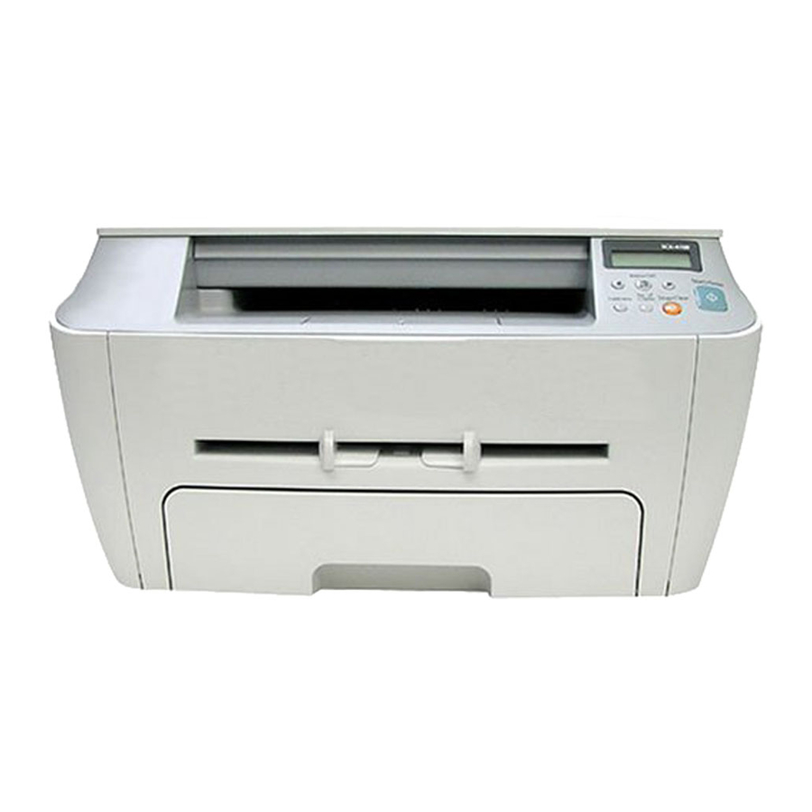
Summary of product 4. Summary of Product This chapter describes the functions and operating principles of the main component. 4.1 Printer Components 4.1.1 Front View Service Manual Samsung Electronics... -
Page 23: Rear View
Summary of Product 4.1.2 Rear View Service Manual Samsung Electronics... -
Page 24: Control Panel
Summary of product 4.1.3 Control Panel Service Manual Samsung Electronics... -
Page 25: System Layout
Summary of Product 4.2 System Layout SCAN PART Service Manual Samsung Electronics... -
Page 26: Paper Feed Mechanism
4.2.4 Fixing Part(Fuser) There are two types of fuser unit: Q-PID type, developed by Samsung, and only used on 220V Domestic models Heat Lamp type used on 220V Export models and all 110V models. The Heat Lamp type fuser consists of the Heat Lamp, Heat Roller, Pressure Roller, Thermistor, and Thermostat. It fixes toner to the paper using pressure and heat to complete the printing job. -
Page 27: Scanner Unit
• CIS Driver Circuit - CIS Clock : 4.16MHz - Voltage Reference : 1.1V - CIS Line Time : 1.67ms/Line x 3Color(600dpi) • Scan Motor Driver Circuit - Motor Driver : SIA403A - Used Volt : 24V DC Service Manual Samsung Electronics... - Page 28 The controller detects the /HSYNC signal to adjust the vertical line of the image on paper. In other words after the /HSYNC signal is detected the image data is sent to the LSU to adjust the left margin on the paper. Service Manual Samsung Electronics...
-
Page 29: Toner Cartridge
- OPC Cleaning: Electrostatic process - Management of waste toner: Electro static process(Cleanerless Type) - OPC Drum protecting Shutter: No - Classifying device for toner cartridge: ID is classified by interruption of the frame channel 0.22mW -330V -970V -480V Service Manual Samsung Electronics... -
Page 30: Main Pba
Circuits on the PBA drive include the main motor (paper feed, cartridge, fuser), clutch driver, pre-transfer lamp driver, heat-lamp driver, CIS driver, scan motor driver and fan driver. The signals from the paper feed jam sensor and paper empty sensor are inputted to the main board from the power supply PBA. Service Manual Samsung Electronics... -
Page 31: Flash Memory
• Access Time : 70 nsec 4.3.3 SDRAM This is used as a buffer, system working memory area, etc. while printing and scanning. • Capacity : SCX-4100 8 M byte • Access Time : 15 nsec 4.3.4 Sensor input circuit 1) Paper Empty Sensing The Paper Empty sensor (Photo Interrupter) on the SMPS/HVPS PBA is monitored by the CPU. - Page 32 The motor driving circuit is activated when the Driver IC is enabled. An AN44060 (Motor driver IC) is used in this case. The resistance Rs value of sensing and the voltage value of the V reference can be changed by the motor driving volt- age value. Service Manual 4-11 Samsung Electronics...
- Page 33 (PANEL CON.) 220V : 250V 2A H 220V : 250V T 5A H (H/L CON.) MHV OPC SUPPLY COVER OPEN SWITCH MANUAL SENSOR FEED SENSOR PAPER-EMPTY SENSOR EXIT SENSOR MAIN PBA CON. F101 250V L2A Service Manual 4-12 Samsung Electronics...
- Page 34 When the ZENER diode is disconnected a blank page is printed out. (It is the same when a ZENER diode is disconnected from OPC ground.) Service Manual 4-13 Samsung Electronics...
- Page 35 AVG : 60 Wh PRINTING 1.0 A 0.5A 1.0 A AVG : 300 Wh Sleep-Mode 0.2A 0.02A 0.03A AVG : 10 Wh 4) Length of Power Cord : 1830 ± 50mm 5) Power Switch : Fitted Service Manual 4-14 Samsung Electronics...
-
Page 36: Fuser Ac Power Control
PC1 is off, the voltage is cut off at the gate of Triac THY1, this Triac is therefore off, and thus the heat lamp is turned off. 1) Triac (THY1) feature - 12A,600V SWITCHING 2) Phototriac Coupler (PC3) - Turn On If Current : 15mA ~ 50mA(Design: 16mA) - High Repetive Peak Off State Voltage : Min 600V Service Manual 4-15 Samsung Electronics... - Page 37 This voltage is fed back into the set through the A/D converter. Based on this fed back value the PWM cycle is changed to maintain the required transfer voltage Page 4-10 has a different chip number Which is correct Service Manual 4-16 Samsung Electronics...
- Page 38 Error Description Polygon motor error When the polygon motor’s speed doesn’t reach operating speed Hsync error The polygon motor’s speed is normal, but the Hsync signal is not created. Service Manual 4-17 Samsung Electronics...
- Page 39 Summary of Product MEMO Service Manual 4-18 Samsung Electronics...
-
Page 40: Disassembly And Reassembly
3. Unplug the power cord. 4. Use a flat and clean surface. 5. Replace only with authorized components. 6. Do not force plastic-material components. 7. Make sure all components are in their proper position. Service Manual Samsung Electronics... - Page 41 1. Take the Cassette out of the printer. 3. Remove the 4 screws securing the Rear Cover and remove it, as shown below. Rear Cover Cassette 2. Remove the Front Cover in the direction of arrow. Service Manual Samsung Electronics...
-
Page 42: Side Covers
Frame Assembly. -Front Cover (see page 5-2) Left Cover 2. Remove 1 screw at the front of the unit. Unclip the right cover along the top edge and remove it from the Frame Assembly. Right Cover Service Manual Samsung Electronics... - Page 43 -Rear Cover (see page 5-2) -Side Cover(Left Cover, Right Cover)(see page 5-3) Scanner Ass’y 2. Remove the 2 connectors from the main PBA and release the ground wire from the Motor Drive Ass’y as shown below. Service Manual Samsung Electronics...
- Page 44 3. Remove the CCD Cable, as shown below. FFC Cable Platen Cover 2. Release 8 clips (2 per side) securing the scanner upper frame to the scanner lower frame and remove the upper frame Scan Upper Service Manual Samsung Electronics...
- Page 45 Scanner Module ETC Belt Pulley Bracket CIS Shaft 7. Remove the 2 screws and take out the Scan Motor Ass'y. 5. Push the Belt Holder and take out the Belt, as shown below. Scan Motor Belt Ass’y Service Manual Samsung Electronics...
-
Page 46: Middle Cover
1. Disconnect the OPE harness from the Main PBA and 2. Remove the 4 screws securing the OPE Unit from the remove the 4 screws securing the Middle Cover. Middle Cover. Remove it, as shown below. Middle Cover OPE Unit OPE Harness Service Manual Samsung Electronics... - Page 47 Heat Roller care not to damage the Exit Sensor. Fuser Ass’y Halogen Lamp 5.Remove 1 screw and take the Idle Gear out. Idle Gear 3. Remove 2 screws and take the Thermostat out of the Fuser. Thermostat Service Manual Samsung Electronics...
- Page 48 Disassembly and Reassembly 6. Remove 4 screws and divide the Fuser into two parts. 8. Remove the Thermister from the Fuser Cover. Fuser Cover Thermister 7. Unwrap the Thermistor Harness, as shown below. Thermister Harness Service Manual Samsung Electronics...
-
Page 49: Exit Roller
3. Unplug 4 screws and take the LSU out. - Rear Cover (see page 5-2) - Side Covers (see page 5-3) - Scanner Ass’y (see page 5-4) - Middle Cover (see page 5-6) 2. Unplug 2 connector from the LSU. Service Manual 5-10 Samsung Electronics... - Page 50 - Left Side Cover (see page 5-3) 2. Remove the 6 screws from the Drive Ass’y. Note when re-fitting the motor Drive Ass’y tighten the screws in the order that they are numbered on the Motor Drive Ass’y base plate. Service Manual 5-11 Samsung Electronics...
- Page 51 Main PBA. Then lift the Main PBA out as shown - Rear Cover (see page 5-2) below. - Side Covers (see page 5-3) - Fuser Connector (see page 5-7) Main PBA - Engine Shield Ass'y (see page 5-11) Service Manual 5-12 Samsung Electronics...
- Page 52 - Engine Shield Ass'y (see page 5-11) 2. Unplug 1 connector and remove 3 screws then take the Inlet Bracket out. Inlet Bracket 3. Remove 1 screw and unplug 1 connector from the Main PBA. Service Manual 5-13 Samsung Electronics...
-
Page 53: Transfer Roller
3. Unplug the PTL Holder Connector then remove the PTL Holder and PTL Lens as shown below. Take care to note the orientation of the PTL lens and ensure it is refitted correctly Lens Holder Service Manual 5-14 Samsung Electronics... -
Page 54: Feed Roller
Feed Gear2 3. Pull up the Feed Idle Bush and Feed Idle Shaft, as Idle Gear shown below. Feed Idle Shaft Bush 6. Remove the Feed Gear 1 Ass’y, as shown below. Feed Gear1 Ass’y Service Manual 5-15 Samsung Electronics... - Page 55 Disassembly and Reassembly 7. Remove the Feed Roller and Feed Roller1, as shown below. Feed Roller Feed Roller1 Service Manual 5-16 Samsung Electronics...
- Page 56 - Feed Bracket and Gears (See page 5-14 steps 4 - 6) (Pick up) Solenoid 2. Remove the Pick up Gear Ass’y, as shown below. (Regi) Solenoid Pick up Gear Ass’y 3. Remove the Pick up Ass’y, as shown below. Bush Pick up Ass’y Service Manual 5-17 Samsung Electronics...
- Page 57 Disassembly and Reassembly MEMO Service Manual 5-18 Samsung Electronics...
-
Page 58: Alignment And Adjustments
1 : On, 2 : Off (-1000V +300V/-150V) THV ON (1300V) 1 : On, 2 : Off (+1300V ± 20V) THV ADC 1300V 1 : On, 2 : Off THV ADC 600V~3550V 1 : On, 2 : Off (Compare each ADC Value) Service Manual Samsung Electronics... -
Page 59: Paper Path
4) The paper then passes through the paper exit sensor and out of the set. (Jam 2 occurs if the trailing edge of the paper does not pass the exit sensor within a certain time of the paper leading edge activating the exit sensor) Service Manual Samsung Electronics... -
Page 60: Clearing Paper Jams
If there is any resistance and the paper does not move when you pull or if you cannot see the paper in this area, skip to the fuser area around the toner cartridge. See page 6-5 Service Manual Samsung Electronics... -
Page 61: In The Paper Exit Area
If there is any resistance and the paper does not move when you pull or if you cannot see the paper in the jam cover, continue to step 6. Service Manual Samsung Electronics... -
Page 62: In The Fuser Area Or Around The Toner Cartridge
The error message may also occur when the paper is not properly fed into the machine through the manual feeder. In that case, pull the paper out of the machine. Service Manual Samsung Electronics... -
Page 63: Printing The System Data List
4 When the display asks you to confirm your selection, press Start/Enter. The machine prints a cleaning page. Toner particles on the drum surface are affixed to the paper. 5 If the problem remains, repeat steps 1 through 4. Service Manual Samsung Electronics... -
Page 64: Consumables And Replacement Parts
• A paper jam has occurred in the manual • Clear the jam. feeder or the machine detects non- feeding from the manual feeder. Paper has jammed in the paper exit area. Paper Jam 2 Clear the jam. Check Inside Service Manual Service Manual Samsung Electronics Samsung Electronics... -
Page 65: Periodic Defective Image
Black spot and image ghost Pressure Roller 59.7mm black spot on the backside L S U Fuser Toner Cartridge MP Sensor Tramsfer Roller OPC Drum SCAN PART Heat Roller Charge Roller Pressure Roller Supply Roller Developing RollerService Manual Samsung Electronics... -
Page 66: Troubleshooting
Remove if found. 5. Contamination of the OPC drum. 5. If the problems are not solved, replace the toner cartridge. 6. Depression or deformation of the surface 6. Replace the transfer roller. of the transfer roller Service Manual Samsung Electronics... -
Page 67: Horizontal Black Bands
If the roller's life is expired, transfer roller's life has expired. replace it. Note. Cleaning the inside of the set to remove excess toner particles or paper dust will reduce the occurrence of this problem.. Service Manual Samsung Electronics... -
Page 68: Light Image
Note if 1 and 2 do not resolve the problem Digital Printer and the problem persists replace the HVPS. 3. VD0 signal of the Main PBA is Low state. 3. Replace the LSU Unit or Main PBA. Service Manual Samsung Electronics... -
Page 69: Uneven Density
4. Is the movement(Up and Down) of 4. Clean the transfer roller bushes. the transfer roller smooth? 5. Is the HVPS normal? 5. Clean the high voltage charge terminals. If this does not resolve the problem replace the HVPS. Service Manual Samsung Electronics... - Page 70 Digital Printer OHP, a higher transfer voltage is required. Remember to set back to normal paper after Digital Printer use. Digital Printer Digital Printer Service Manual Samsung Electronics...
- Page 71 2. If the transfer roller is contaminated, run Digital Printer stains on the face of page will occur. PC Cleaning Mode Print 2 or 3 times and Digital Printer then perform Self-Test 2 or 3 times to remove contamination. Service Manual Samsung Electronics...
- Page 72 3. When the printer turns on, several blank pages print. Check and Cause Solution 1. Abnormal solenoid. 1. Perform the engine self test using TECH Mode to check if the Solenoid is normal. If the problem persists replace the main Service Manual Samsung Electronics...
-
Page 73: Copy Problems
Black page is printed out when Copying. Check and Cause Solution 1. Check for CIS problem on the Main PBA. 1. Check the CIS harness is properly connected. 2. Check shading profile. 2. Redo shading profile in the tech mode. Service Manual Samsung Electronics... -
Page 74: Defective Image Quality
2. Check the gap between original and scanner 2. A gap of more than 0.5 mm can cause a blurred glass. image. Ensure rollers and cover close correctly. Replace as necessary. 3. Check printing quality. 3. See "Print" troubleshooting. Service Manual Samsung Electronics... -
Page 75: Wrong Print Position
6 If the paper feeds into the printer and 6. Check the SMPS PBA, Main PBA and Jam 0 occurs, perform Tech Mode to all connections. Replace any faulty check feed sensor. parts or the Service Manual 7-10 Samsung Electronics... - Page 76 Check all ribs, claws and springs. • It occurs when the Spring of a Guide claw is broken or damaged. • It occurs when the Heat-Roller or Pressure-Roller is seriously contaminated with toner. Service Manual 7-11 Samsung Electronics...
-
Page 77: Paper Rolled In The Fuser
Clean the surface of the rollers with IPA or water 2. Damaged or deformed ribs, claws or springs. 2. Check for damage or deformation of the print claws and the holder plate claws, and repair or replace as appropriate. Service Manual 7-12 Samsung Electronics... -
Page 78: Paper Rolled On The Opc Drum
Use the gearwheel at the side to rotate the OPC drum and pull the paper from the cassette. • Clean fingerprints on the OPC gently with soft tissue, taking care not to scratch the surface. Service Manual 7-13 Samsung Electronics... -
Page 79: Fuser Error
Use TECH mode to test the LSU - Replace the LSU 2. LSU motor is faulty. - Replace a main board if the same error persists after replacing a LSU. 3. Check the HSYNC signal. Service Manual 7-14 Samsung Electronics... -
Page 80: Paper Empty
1. Deformed paper sensor actuator or faulty sensor. 1. Replace the defective actuator or sensor. 2. SMPS PBA or Main PBA is defective 2. Replace the SMPS PBA or MAIN PBA as appropriate. 3. Faulty cables or connectors. Service Manual 7-15 Samsung Electronics... -
Page 81: Cover Open
2. The tab on the front cover may be damaged or broken 2. Replace the front cover. 3. Check the connector and cables between Switch and 3. Replace the Main Control board or Cover Open main PBA. S/W as necessary. Service Manual 7-16 Samsung Electronics... - Page 82 1. Use TECH mode(“cover sensor test”) to check cover switch operation. Check and replace switch if necessary. 2. Check the connector and cables between Switch and main PBA. 2. Replace the Main Control board or Cover Open S/W as necessary. Service Manual 7-17 Samsung Electronics...
-
Page 83: Defective Motor Operation
2. LCD panel does not come on but normal start up 2. Replace the OP panel. sounds are heard. 3. After replacing SMPS display does not come on and no 3. Replace the main PBA panel. start up sounds are heard. Service Manual 7-18 Samsung Electronics... - Page 84 When printing, vertical lines are not straight. Check and Cause Solution 1. Check stability of 24V supply to LSU. 1. 24V stable - Replace LSU. 24V unstable replace SMPS, if the problem persists replace the main PBA. Service Manual 7-19 Samsung Electronics...
-
Page 85: Service For The Life Of Toner Cartridge
Troubleshooting 7.5 Toner Cartridge Service Only toner cartridges supplied by Samsung should be used. Printing defects or set damage caused by the use of non-approved toner cartridges or un-licensed toner refills are not covered by the guarantee. 7.5.1 Precautions on Safe-keeping of Toner Cartridge Excessive exposure to direct light for more than a few minutes may cause damage to the cartridge. - Page 86 (a) Check that the terminals problem persists replace the (contact points) of the toner cartridge. cartridge and the set are clean. (b) Check that the terminals (contact points) of the toner cartridge and the set are not damaged. Service Manual 7-21 Samsung Electronics...
- Page 87 (contact point) of the toner toner cartridge is recycled over cartridge and the set are not 2 times. damaged. If ‘nearly empty’ cartridges are collected for re-use this is judged as recycling the toner cartridge. Service Manual 7-22 Samsung Electronics...
- Page 88 (a) Check if foreign substances are stuck to the terminal (point of contact) of the toner cartridge or set. (b) Check if the terminal assembly is normal. (Especially check the developer roller terminal.) Service Manual 7-23 Samsung Electronics...
- Page 89 9and perhaps even uninstalling their dri- vers) to ensure the printer works by itself. If you are using a USB hub try connecting directly to the back of the PC instead. Service Manual 7-24 Samsung Electronics...
- Page 90 Turn the PC and printer off, and reboot the system to print again. If not solved, double-click the printer in my computer If the regular fonts are not printed this time again. the cable must be defective so replace the cable with new one. Service Manual 7-25 Samsung Electronics...
-
Page 91: Abnormal Printing
2. Ensure that the correct driver is loaded. Use the driver supplied on the CD or downloaded from the Samsung web site. DO NOT use the Microsoft driver supplied with the Windows operating system. If the printer is a GDI or SPL type printer ensure that... -
Page 92: Spool Error
If there is a problem with the printer (out of toner, offline, out of paper etc.) the job may take a long time to delete as it must wait for a time out. Service Manual 7-27 Samsung Electronics... - Page 93 Troubleshooting MEMO Service Manual 7-28 Samsung Electronics...
-
Page 94: Exploded Views And Parts List
8.7 Cassette Unit Assembly ........page(8-14) Service Manual Samsung Electronics... -
Page 95: Main Assembly
Exploded View & Parts List 8.1 Main Assembly Frame Toner Cartridge Service Manual Samsung Electronics... - Page 96 EXPLODED VIEW & PARTS LIST Main Assembly Parts List SA : Service Available O : Service available X : Service not available Description SEC.Code Q’ty Remark SCX-4100 MEA UNIT-COVER MIDDLE JC97-01958A SCX-4100 MEA UNIT-COVER REAR JC97-01959A SCX-4100 COVER-M_REAR JC63-00475A COVER-M_REAR DOOR...
-
Page 97: Frame Assembly
Exploded View & Parts List 8.2 Frame Assembly Service Manual Samsung Electronics... - Page 98 IPR-P-GROUND_EARTH TR JC70-00309A SPRING-ETC 6107-001162 ROLLER-FEED ROLLER 1 JC66-00526A PMO-BUSHING FEED JC72-00382B ROLLER-FEED JC66-00598A SPRING-TS 6107-001165 Spring-act,Manual IPR-P-EARTH TRANSFER JC70-00307A HOLDER-PTL JC61-00583A LENS-PTL JC67-00027A BUSH-M-TR L JC61-00588A SPRING ETC-TR L HAWK JC61-00047A SPRING-TS 6107-001165 Spring-act,Feed PMO-BUSHING_TR(L) JC72-00102A Service Manual Samsung Electronics...
- Page 99 58-7 HOUSING-M-PICK_UP JC61-00591A MEA UNIT-CLUTCH JC97-01788A 59-1 GEAR-FEED 1 JC66-00393A 59-2 PMO-COLLAR_SPRING JC72-00978A 59-3 SPRING-TS 6107-001171 59-4 PMO-HUB CLUTCH JC72-00981A ELA HOU-FUSER_220V JC96-03135B 220V ELA HOU-FUSER_110V JC96-03135A 110V RMO-RUBBER EXIT JC73-40915A PBA MAIN-PTL JC92-01620B IPR-GROUND_SAW JC63-00465A Service Manual Samsung Electronics...
-
Page 100: Scanner Unit Assembly
Exploded View & Parts List 8.3 Scanner Unit Assembly Service Manual Samsung Electronics... - Page 101 Exploded View & Parts List Scanner Unit Assembly Parts List SA : Service Available O : Service available X : Service not available Description SEC.Code Q’ty Remark UNIT SCAN JC96-03136A SCX-4100 COVER-M-PLATEN JC63-00454A SHEET-WHITE SPONGE JC63-00209A HINGE PIVOT JC61-00929A COVER-M-SCAN UPPER JC63-00452A GLASS SCAN...
-
Page 102: Fuser Unit Assembly
Exploded View & Parts List 8.4 Fuser Unit Assembly Service Manual Samsung Electronics... - Page 103 ROLLER-M-EXIT F/UP JC66-00380A RUBBER EXIT JC73-00017A ROLLER-PRESSURE JC66-00731A BEARING-PRESSURE/R JC66-10901A SPRING-ETC-BEARING PR JC61-00453A PMO-BUSHING TX JC72-00382A HOLDER-ACTUATOR JC61-00581A PMO-ACTUATOR_EXIT JC72-00987A FRAME_FUSER JC61-00946A GUIDE-M-INPUT JC61-00595A SPRING-TS 6107-001165 NUT-HEXAGON 6021-000222 LABEL(P)-CAUTION, HOT_FUSER JC68-30928D PLATE-P-CLAW JC61-00605A COVER-LAMP_L JC63-00521A Service Manual 8-10 Samsung Electronics...
- Page 104 Fuser Unit Assembly Parts List SA : Service Available O : Service available X : Service not available Description SEC.Code Q’ty Remark WASHER-PLAIN 6031-001051 LABEL(R)-HV FUSER JC68-00407A SCREW-TAPTITE 6006-001078 SCREW-MACHINE 6006-001193 SCREW-TAPTITE 6603-000269 SCREW-TAPTITE 6003-000196 Service Manual 8-11 Samsung Electronics...
-
Page 105: Middle Cover Unit Assembly
Exploded View & Parts List 8.5 Middle Cover Unit Assembly Service Manual 8-12 Samsung Electronics... - Page 106 SEC.Code Q’ty Remark MEA UNIT-COVER MIDDLE JC97-01958A COVER-M_MIDDLE JC63-00473A PMO-STACKER JC72-01340A STOPPER-M-LEVER JC61-00949A SPRING ETC-TS-CHARGE APOLLO JC61-00026A PMO-SUB_M_STACKER JC72-01343A PMO-BUSHING_F/DOWN JC72-00387A WINDOW-M LCD JC64-00153A KEY-M_START JC64-00151A KEY-M_STOP JC64-00150A KEY-M_MENU JC64-00152A PBA SUB-PANEL JC92-01586A COVER-M-PANEL JC63-00474A Service Manual 8-13 Samsung Electronics...
- Page 107 SEC.Code Q’ty Remark ELA UNIT-DRIVE JC96-03138A BRACKET-P-GEAR 1400 JC61-00598A GEAR-RDCN 53/26 JC66-00388A GEAR-RDCN 113/33 JC66-00391A GEAR-RDCN 57/18 JC66-00389A WASHER-PLAIN 6031-000023 BRACKET-P-MOTOR 1400 JC61-00599A GEAR-RDCN 103/41 JC66-00390A GEAR-RDCN 90/31 JC66-00392A MOTOR STEP 7.5 JC31-00020A PMO-IMPELLER_DRV JC72-00825A Service Manual 8-14 Samsung Electronics...
-
Page 108: Cassette Unit Assembly
Exploded View & Parts List 8.7 Cassette Unit Assembly Service Manual 8-15 Samsung Electronics... - Page 109 JC61-00580A SPRING ETC-LOCKER,PLATE JG61-70531A PLATE-P-KNOCK_UP JC61-00603A SPRING-CS 6107-001166 PMO-EXTENSION SMALL JC72-00971A GUIDE-M-EXTENSION L2 JC61-00918B FRAME-M_CASSETTE JC61-00876A PMO-PLATE_LOCKER JC72-00972A SPRING ETC-EXIT ROLL FD JC61-70911A ROLLER-M-IDLE FEED JC66-00529A SPRING-ES 6107-001047 GUIDE-M_CASSETTE JC61-00944A CAM-M-KNOCK_UP JC66-00719A RPR-PAD CASSETTE JC73-00141A Service Manual 8-16 Samsung Electronics...
-
Page 110: Block Diagram
Block Diagram 9. Block Diagram Service Manual Samsung Electronics... -
Page 111: Connection Diagram
Connection Diagram 10. Connection Diagram Service Manual 10-1 Samsung Electronics...