Lenovo H430 User Manual
H4 series
Hide thumbs
Also See for H430:
- Hardware replacement manual (39 pages) ,
- User manual (33 pages) ,
- Specifications (2 pages)

Related Manuals for Lenovo H430


Summary of Contents for Lenovo H430
-
Page 1: User Guide
Machine type: 10080/3099/1194 10091/2558/1196 H4 Series User Guide Version 4.0 2012.08 31502581... -
Page 2: Important Safety Information
Attention: Be aware of possible damage to programs, devices, or data. Note: Pay attention to this important information. © Copyright Lenovo 2012. All rights reserved. LIMITED AND RESTRICTED RIGHTS NOTICE: If data or software is delivered pursuant a General Services Administration “GSA” contract, use, reproduction, or... -
Page 4: Table Of Contents
Contents Important Safety Information Using the Computer Hardware ..........1 Front view of the chassis ................2 Rear view of the chassis ................3 Connecting your computer .................5 5.1 Audio configuration instruction .............7 Connecting the power cord ................8 How to play Blu-ray Discs (selected models only) ........8 Wired keyboard (selected models only) ............9 Connecting to the Internet ................9 Using Windows 8 .............. - Page 5 Troubleshooting Problems with Optical Drives and Hard Disks ....23 Special considerations for troubleshooting Windows ........24 Windows Help and Support ..............24 BIOS setup utility ..................25 Performing Daily Maintenance Tasks ............25 Hardware Replacement Guide ..........27 Locations ....................31 Replacing hardware .................34 Appendix................... 48 Declaration ....................48 Trademarks ....................49 Energy Star Statement ................50...
-
Page 6: Using The Computer Hardware
Using the Computer Hardware This chapter contains the following topics: Introduction to the computer hardware Information on computer connections Note: The descriptions in this chapter might vary from your computer, depending on computer model and configuration. User Guide... -
Page 7: Front View Of The Chassis
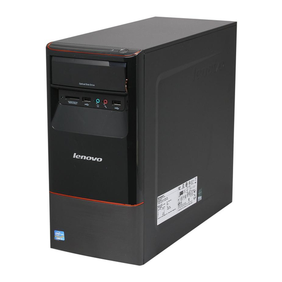
Front view of the chassis Attention: Be sure not to block any air vents on the computer. Blocked air vents can cause thermal problems. Power button Optical Drive (selected models only) Memory card reader (selected models only) USB connector (2) Headphone connector Microphone connector Note: This computer only can be placed in a vertical position. -
Page 8: Rear View Of The Chassis
(If the rear view configuration in this chapter is different from your actual computer, the rear view configuration of your actual computer should be taken as final and binding.) Lenovo H430 Voltage selection switch (selected models only) Power connector PS/2 keyboard connector (selected models only) - Page 9 Audio line-out connector Audio line-in connector Standalone graphic card (selected models only) Expansion card slots (access connectors for any installed PCI express cards) Lenovo H415 Voltage selection switch (selected models only) Power connector On-board VGA connector (selected models only) HDMI connector (selected models only)
-
Page 10: Connecting Your Computer
Audio line-in connector PCI Express X 16 graphics adapter slot (some models are equipped with a graphic card) PCI Express X 1 adapter slots (some models are equipped with a WIFI card or TV tuner card) Connecting your computer Use the following information when connecting your computer. •... -
Page 11: Basic Connector Instructions
Basic connector instructions Connector Description Microphone Use this connector to attach a microphone to your computer when you want to record sound or if you use speech-recognition software. Headphone Use this connector to attach headphones to your computer when you want to listen to music or other sounds without disturbing anyone. -
Page 12: 5.1 Audio Configuration Instruction
5.1 Audio configuration instruction (These instructions are only for models whose motherboard supports audio transformation from 2.0 stereo sound to 5.1 surround sound.) This model of computer supports transforming stereo sound into 5.1 surround sound. Use the following guides when connecting to the 5.1 surround audio device. Blue line-in connector Surround Green line-out connector... -
Page 13: Connecting The Power Cord
Connecting the power cord How to play Blu-ray Discs (selected models only) Check the connectors available on your computer and display and select an appropriate cable according to the table below. Other types of cables do not meet the requirements of the Blu-ray standard. You need to purchase the cable separately if the computer is not equipped with the corresponding cable. -
Page 14: Wired Keyboard (Selected Models Only)
Wired keyboard (selected models only) LVT —— After entering Windows, press this key to launch the LVT (Lenovo Vantage Technology) program, Lenovo’s pre-loaded Home PC software. In addition to its own functions, the LVT program will allow you to start other Windows compatible software specially configured to run on this model of computer. - Page 15 User Guide...
-
Page 16: Using Windows 8
Using Windows 8 This chapter contains the following topics: Switching between the main Windows 8 interfaces The Charms Bar Shutting down the computer Switching between apps Closing an app Opening other system programs Windows Help and Support Attention: The Windows 8 operating system is provided by Microsoft Corporation. -
Page 17: Switching Between The Main Windows 8 Interfaces
Switching between the main Windows 8 interfaces Windows 8 comes with two main user interfaces: the Start Screen and the Windows desktop. To switch from the Start Screen to the Windows desktop, do one of the following: • Select the Windows desktop tile on the Start Screen. •... -
Page 18: Closing An App
Closing an app To close an app, do one of the following: • Move the cursor to the top left corner of the screen. When the thumbnail appears, drag it to the bottom of the screen. • Swipe in from the top edge of the screen. When the app page becomes smaller, drag it to the bottom of the screen. - Page 19 User Guide...
-
Page 20: Using The Rescue System
Using the Rescue System This chapter contains the following topics: OneKey Recovery Driver and Application Installation Attention: Using OneKey Recovery will result in loss of data. • You can restore the C: drive of the computer to factory default settings or to the last system backup status using OneKey Recovery. -
Page 21: Onekey Recovery
Note: The recovery files and relevant data used by the rescue system are saved in the service partition. If the service partition is deleted or damaged by someone other than authorized Lenovo service personnel, Lenovo will not be liable for any losses arising therefrom in any way. -
Page 22: Driver And Application Installation
Driver and Application Installation The Driver and Application Installation function in the rescue system provides a way for the user to conveniently reinstall all of the Lenovo applications and drivers that were shipped with your Lenovo hardware. Method 1: Automatic Installation Repeatedly press and release the F2 key after turning on the computer until the Lenovo Rescue System opens, then select Drivers and Application Installation. - Page 23 User Guide...
-
Page 24: Troubleshooting And Confirming Setup
Troubleshooting and Confirming Setup This chapter contains the following topic: Troubleshooting and Problem Resolution Note: The description of the TV tuner card in this manual is only applicable to machines which have the TV tuner card. It does not apply to machines that do not have a TV tuner card. -
Page 25: Troubleshooting Display Problems
Solving Problems Follow these tips when troubleshooting your computer: • If you added or removed a part before the problem started, review the installation procedures to ensure that the part is correctly installed. • If a peripheral device does not work, ensure that the device is properly connected. -
Page 26: Troubleshooting Audio Problems
2. Move any interfering devices away from the computer. 3. If the problem persists, contact Lenovo Service. Troubleshooting Audio Problems Problem: No sound from the integrated speakers. Troubleshooting and problem resolution: •... -
Page 27: Troubleshooting Software Problems
Troubleshooting Software Problems Problem: You are unable to exit a running program normally. Troubleshooting and problem resolution: 1. Open the Task Manager window by pressing Ctrl, Alt and Delete at the same time. 2. Select the problem program, then click the End Task button. Problem: You need to install or uninstall a program. -
Page 28: Troubleshooting Problems With Optical Drives And Hard Disks
1. Check to determine if there is an optical drive icon in the resource manager of the operating system. If not, restart your computer. If there is still no icon, contact Lenovo Service. Otherwise, continue with the next step of this procedure. -
Page 29: Special Considerations For Troubleshooting Windows
The capacity of the hard disk as calculated using this method may be slightly different from the actual capacity due to the rounding of totals. Special considerations for troubleshooting Windows Record the following information as it may be useful later when troubleshooting system problems: 1. -
Page 30: Bios Setup Utility
BIOS setup utility What is the BIOS setup utility? The BIOS setup utility is ROM-based software. It communicates basic computer information and provides options for setting boot devices, security, hardware mode, and other preferences. How can I start the BIOS setup utility? To start the BIOS setup utility: 1. - Page 31 The following are general methods for cleaning the components: • You can use a soft cloth to remove dust on the surface of the computer, the monitor, the printer, the speakers and the mouse. • You can use a vacuum cleaner to clean in otherwise inaccessible corners. •...
-
Page 32: Hardware Replacement Guide
Hardware Replacement Guide This chapter contains the following topics: Locating components Identifying parts on the system board Removing the computer cover Removing and replacing the front bezel Replacing a memory module Replacing the hard disk drive ... - Page 33 Safety and Warranty Guide that was included with your computer. If you no longer have this copy of the Safety and Warranty Guide, you can obtain one online from the Support Web site at http://support.lenovo.com. User Guide...
-
Page 34: Additional Information Resources
• Parts information • Links to other useful sources of information To access this information, go to http://support.lenovo.com. Tools required To disassemble the computer, you need the following tools: • Wrist grounding strap and conductive mat for preventing electrostatic discharge •... - Page 35 Handling static-sensitive devices Static electricity is harmless to you, but it can seriously damage computer components. When you are replacing a part, do not open the antistatic package containing the new part until the defective part has been removed from the computer and you are ready to install the new part.
-
Page 36: Locations
Locations This section provides illustrations to help locate the various connectors, controls and components of the computer. To remove the computer cover, refer to “Removing the computer cover”. Locating components The following illustration will help you to locate the various components in your computer. -
Page 37: Identifying Parts On The System Board
It provides basic computer functions and supports a variety of devices that are factory-installed or that you can install later. The following illustrations show the locations of parts on the system board. Lenovo H430 Microprocessor and heat sink Microprocessor fan connector... - Page 38 Front USB connectors (2) Front audio connector PCI express X 1 adapter connectors (3) PCI express X 16 adapter connector System fan connector 12V power connector Lenovo H415 Microprocessor and heatsink Microprocessor fan connector Memory connectors (2) Thermal sensor header connector Power connector...
-
Page 39: Replacing Hardware
Maintenance Manual (HMM) for the computer. To obtain copies of the Safety and Warranty Guide or HMM, go to the Support Web site at http://support.lenovo.com Note: Use only parts provided by Lenovo. Removing the computer cover Attention: Turn off the computer and wait three to five minutes to let it cool down before removing the cover. - Page 40 5. Slide the computer cover to the rear of the chassis to remove it. Note: For this procedure, it helps to lay the computer on its side. User Guide...
-
Page 41: Removing And Replacing The Front Bezel
Removing and replacing the front bezel To remove and replace the front bezel: 1. Remove the computer cover. Refer to “Removing the computer cover”. Note: For this procedure, it helps to lay the computer on its side. 2. Remove the front bezel by releasing the three plastic tabs inside the chassis and pushing the bezel outward as shown. -
Page 42: Replacing A Memory Module
Maintenance Manual (HMM) for the computer. To obtain copies of the Safety and Warranty Guide or HMM, go to the Support Web site at http://support.lenovo.com. To replace a memory module: 1. Remove the computer cover. Refer to “Removing the computer cover”. -
Page 43: Replacing The Hard Disk Drive
Maintenance Manual (HMM) for the computer. To obtain copies of the Safety and Warranty Guide or HMM, go to the Support Web site at http://support.lenovo.com. To replace the hard disk drive: 1. Remove the computer cover. Refer to “Removing the computer cover”. -
Page 44: Replacing An Optical Drive
Maintenance Manual (HMM) for the computer. To obtain copies of the Safety and Warranty Guide or HMM, go to the Support Web site at http://support.lenovo.com. To replace an optical drive 1. Remove the computer cover. Refer to “Removing the computer cover”. - Page 45 5. Push the optical drive straight out of the front of the chassis. 6. Slide the new optical drive into the bay from the back until it snaps into position. 7. Secure the optical drive to the bay with the two screws. 8.
-
Page 46: Replacing The Heatsink Assembly
Maintenance Manual (HMM) for the computer. To obtain copies of the Safety and Warranty Guide or HMM, go to the Support Web site at: http://support.lenovo.com To replace the heatsink assembly: 1. Remove the computer cover. Refer to “Removing the computer cover”. - Page 47 7. Use the thermal grease syringe to place five drops of grease on the top of the microprocessor. Each drop of grease should be 0.03ml (3 tick marks on the grease syringe). 8. Install the heatsink and fan assembly onto the heatsink retention bracket. 9.
-
Page 48: Replacing A Pci Or Agp Adapter
Maintenance Manual (HMM) for the computer. To obtain copies of the Safety and Warranty Guide or HMM, go to the Support Web site at: http://support.lenovo.com. To replace an adapter: 1. Remove the computer cover. Refer to “Removing the computer cover”. - Page 49 3. Install the new adapter into the same adapter connector. 4. Ensure the adapter is fully seated into the adapter connector. 5. Screw the latch into the chassis. 6. Refer to “Completing the installation”. User Guide...
-
Page 50: Replacing The Keyboard And Mouse
Maintenance Manual (HMM) for the computer. To obtain copies of the Safety and Warranty Guide or HMM, go to the Support Web site at http://support.lenovo.com. To replace the keyboard: 1. Remove any media (disks, CDs, or memory cards) from the drives, shut down the operating system, and turn off the computer and all attached devices. -
Page 51: Completing The Installation
Completing the installation After replacing a part or parts, you must close the computer cover and reconnect all the cables, including telephone lines and power cords. Some parts will require confirming updated information in the Setup Utility program. Refer to “Starting the Setup Utility”... - Page 52 “Locating connectors on the front of the computer” and “Locating connectors on the rear of the computer”. Note: In most areas of the world, Lenovo requires the return of the defective CRU. Information about this will come with the CRU or will come a few days after the CRU arrives.
-
Page 53: Appendix
Thank you for using Lenovo products. Carefully read all documents shipped with your computer before you install and use the product for the first time. Lenovo is not responsible for any loss except when caused by installation and operations performed by Lenovo professional service personnel. -
Page 54: Trademarks
Phenom, AMD Sempron, Catalyst, Cool ‘n’ Quiet, CrossFire, PowerPlay, Radeon, and The Ultimate Visual Experience are trademarks of Advanced Micro Devices, Inc. Other company, product, or service names referred to herein or in other Lenovo publications may be trademarks or service marks of others. All rights reserved. -
Page 55: Energy Star Statement
For more information about ENERGY STAR, go to: http://www.energystar.gov. Lenovo encourages you to make efficient use of energy an integral part of your day-to-day operations. To help in this endeavor, Lenovo has preset the following... -
Page 56: Enabling Erp Compliance Mode
Enabling ErP compliance mode You can enable the energy-related products directive (ErP) compliance mode through the Power menu in the Setup Utility program. This mode reduces electricity consumption when your computer is in standby mode or turned off. To enable ErP compliance mode in the Setup Utility program, do the following: 1. - Page 57 User Guide...