
Related Manuals for Fujitsu MB2146-07-E


Summary of Contents for Fujitsu MB2146-07-E
- Page 1 FUJITSU SEMICONDUCTOR SS702-00001-2v0-E SUPPORT SYSTEM New 8FX Family 8-bit MICROCONTROLLER BGM ADAPTOR MB2146-07-E OPERATION MANUAL...
- Page 2 The product is a development support tool for developing and evaluating applied products which use Fujitsu Semiconductor microcontrollers (hereafter MCU) that have a BDSU module. This manual describes how to handle the New 8FX Family All Series BGM adapter. Be sure to read it before using the product.
- Page 3 ■ Caution of the products described in this document The following precautions apply to the product described in this manual. Indicates a potentially hazardous situation which could result in death or serious WARNING injury and/or a fault in the user’s system if the product is not used correctly. Before performing any operation described in this manual, turn off all the power Electric shock, supplies to the system.
- Page 4 • Nothing contained in this document shall be construed as granting or conferring any right under any patents, copy- rights, or any other intellectual property rights of FUJITSU SEMICONDUCTOR or any third party by license or oth- erwise, express or implied. FUJITSU SEMICONDUCTOR assumes no responsibility or liability for any infringement of any intellectual property rights or other rights of third parties resulting from or in connection with the information contained herein or use thereof.
- Page 5 1. Checking the Delivered Product Before using the product, make sure that the package contains the following items: • BGM adaptor * • USB cable (1.0m) • Interface cable • Hardcopy (China RoHS report) * : Referred to as the adaptor.
- Page 6 2. Introduction MB2146-07-E is a tool used for Fujitsu Semiconductor New 8FX MCU. It is updated from MB2146- 08-E and silimar to MB2146-08-E in appearance. MB2146-07-E has inherited all functions of MB2146-08-E. It is updated to obtain a better performance and new functions.
-
Page 7: System Configuration
See "SOFTUNE Workbench OPERATION MANUAL" for the de- tails on the emulation debugger software operation in the host computer. Figure1 shows the system construction when used as the emulator system. Gates circuit Debug PC USB Target USB socket interface interface MB2146-07-E Figure 1 System Configuration... -
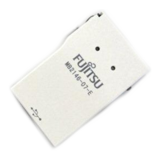
Page 8: Interface Overview
4. Interface Overview This chapter describes the BGMA interface. 4.1 MB2146-07-E Appearance Figure 2 shows the BGMA appearance User interface connector Mode key Interface cable Status LED Power supply Power supply USB connector Figure 2 BGMA Appearance... - Page 9 *1 : BGMA means the BGM adaptor. *2 : MCU means the evaluation MCU. Note : The MB2146-07-E pin assignment has no compatibility with the MB2146-09 and MB2146-09A-E pin assignments. It is impossible to use these two BGM adaptors for different MCUs. If used by mistake, there is a possibility that the debug system will not operate correctly or could be damaged.
-
Page 10: Feature List
5. Feature list ■ Function Description of BGMA The MB2146-07-E BGMA is updated from MB2146-08-E. The updated features are described be- low. • BGMA power supply is DC 5V (Power supply from the USB pin) • UART Baud rate Max speed improved:... -
Page 11: Performance Description
6. Performance Description ■ Operating Description of BGMA This chapter describes the BGMA operation. 6.1 Debug Function Open the project file in S Workbench which supports New 8FX and execute the setup related OFTUNE to the debug. The following shows the supplemental description about the special settings. 6.1.1 ICE Type Select, the ICE type MB2146-07. - Page 12 6.1.4 Settings of Oscillation and Communication Speed In this dialig box, a user can select MCU external clock value in Frequency (main) Field, and enable or disable clock up in Response Speed Optimization Field. Figure 5 Clock Setting 6.1.5 Power Supply To Target This item enables BGMA to supply power to the target MCU board.
- Page 13 6.1.6 Flash Memory Synchronization This dialog box is used to select the Flash memory synchronous function when starting debug. If the dialog box is selected, the S will read all MCU flash data to S OFTUNE OFTUNE Figure 7 Flash Synchronization...
- Page 14 RAM Monitoring Function When debugging, a user can open RAM Monitoring Window to watch the MCU RAM status. User can watch 32 bytes RAMs on the RAM Monitoring at the same time. Figure 8 RAM Monitoring Window 6.2.1 Enable RAM Monitoring Function Right-click the blank area in the RAM Monitoring Window and select monitoring from the shortcut menu to enable the RAM Monitoring function, as shown in Figure 9.
- Page 15 6.2.2 Set Register Select Setup from the shortcut menu in Figrue 9, and RAM Monitoring Setup window pops up, as shown in Figure 10. Figure 10 RAM Monitoring Setup Set the RAM to be watched in Address field, and select Word from the Size Drop-down List Box. When the address and size are selected, a user can click “Append”...
- Page 16 7. How to Upgrade BGMA FW (firmware) This chapter describes how to update the BGMA FW. The BGMA FW can be updated by PC. The tool “PC Helper.exe” can be used to update the FW. The following section describes the upgrading of BGMA FW in detail. 7.1 Use S Upgrade FW OFTUNE...
- Page 17 (4) Enable S Upgrade function. OFTUNE Select “Monitor program auto-loading” in S . For the detailed operation, see sector 6.1.2. OFTUNE Figure 14 Enable Softune Upgrade function (5) Right-click S “Debug” and select “start debug”. OFTUNE Figure 15 Start Debug Icon...
- Page 18 (6) When the following window pops up, turn off the power supply of target board. Figure 16 Power-off (7) Press the “OK” button, the following sub-window will pop up. Figure 17 S Upgrade OFTUNE (8) If a user wants to stop the upgrading, press the “Abort” button. (9) If the “Abort”...
- Page 19 7.2 FW Upgrade Using PC Helper Programmer Figure 18 Tool Interface Step: (1) Connect BGMA to PC. (2) Open PC Helper programmer. (3) Open “FW Upgrade”, like the following picture. Figure 19 FW Upgrade Interface (4) If the BGMA item shows “Connected” and the color is green like the picture above, the BGMA and PC connect normally.
- Page 20 (6) When the HEX file is choosen, press “Upgrade” item to upgrate BGMA FW. (7) When the sub-window pops up, select recommend item and “OK”. (8) When downloading is successfully completed, "Download Successful" is shown as follows. Figure 21 Successful Sample...
- Page 21 SS702-00001-2v0-E FUJITSU SEMICONDUCTOR • SUPPORT SYSYEM New 8FX Family 8-bit MICROCONTROLLER BGM ADAPTOR MB2146-07-E OPERATION MANUAL May 2013 the second edition Published FUJITSU SEMICONDUCTOR LIMITED Edited Sales Promotion Department...