Table of Contents
S7999D SOLA
Operator Interface Display
APPLICATION
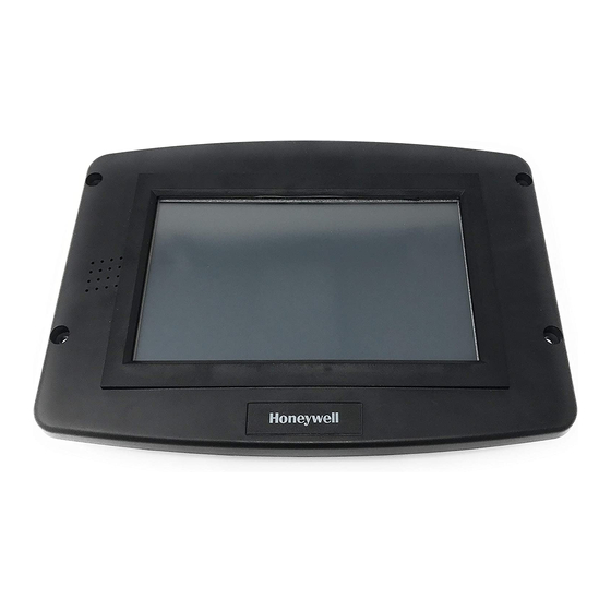
The S7999D is microprocessor-based color touch-screen
Operator Interface (OI) display that provides an operator
interface for monitoring and configuring parameters in the
Sola Hydronic Control and Sola Steam Control system.
The S7999D can be used to monitor an individual boiler but is
also used for multiple boiler applications in a lead/lag
arrangement. It consists of 2 RS485 ports (COM 1 & COM 2)
and USB port. The S7999D display can be flush front or
behind mounted into a panel cutout. Wiring connections to the
S7999D are through a removable 8-pin wiring connector.
FEATURES
• Individual boiler status, configuration, history and
diagnostics
• Allows configuration and monitoring of the Sola
Controls (R7910 Hydronic Controls or R7911 Steam
Control) burner control sequence, flame signal,
diagnostics, historical files, and faults
• Allows switching view between multiple boilers and
lead-lag master/slaves
• Real-time data trending analysis and transferring
saved trend data to Excel spreadsheet
• 7" 800 x 480, 24 bit high resolution color LCD touch
screen for clarity
• Audio output with integral speaker for sound output.
• Adjustable backlight control
• Real time clock with coin-cell battery back up (CR2032)
• Volume control
• Screen Capture function to capture screen images
• USB port for file transfers and software updates
• 2 RS-485 (COM1 & 2) ports for Modbus™ interface to
Sola controls and BAS Gateway.
• Windows® CE 6.0 Operating System
• 8-pin connector, back-up battery and mounting
hardware are provided
PREFACE
This User Guide is intended to provide a general overview of
the S7999D Operator Interface (OI) Displays. It is intended to
guide you through the features and operation of the OI Display
as you interface with the R7910 or R7911 Sola control and
establish the Parameter points of the system.
Note that this sheet shows all parameters. The actual product
may have parameters made invisible or Read Only by
Honeywell as they may not apply to the application.
SPECIFICATIONS
Electrical Ratings:
Input Voltage: 18 – 30 Vac (24Vac nominal), 50/60 Hz
Input Current: 500 mA max
Power consumption: 12W max
Operating Temperature: -4 to 158 ºF (-20 to 70 ºC)
Storage/Shipping Temperature: -22 to 176 ºF ( -30 to 80 ºC)
Humidity: 90% RH, non condensing
Enclosure rating: IP10 / NEMA 1
Approvals:
FCC Part 15, Class A Digital Device
Underwriter's Laboratories, Inc. (UL) (cUL) Component Rec-
ognized (for non-continuous operation): File Number
MH17367 (MJAT2, MJAT8).
Dimension: See Fig. 1
PRODUCT DATA
65-0315-02
Table of Contents

Related Manuals for Honeywell S7999D SOLA


Summary of Contents for Honeywell S7999D SOLA
-
Page 1: Specifications
Read Only by The S7999D can be used to monitor an individual boiler but is Honeywell as they may not apply to the application. also used for multiple boiler applications in a lead/lag arrangement. It consists of 2 RS485 ports (COM 1 & COM 2) and USB port. -
Page 2: Replacement Parts
Replacement Parts • CR2032 coin battery • Mounting hardware 50063482-001 Bag assembly includes: • 3 clamp filters (1 for 24V power and 1 for each Modbus) • 8-pin connector 9-7/16 (240) 8-15/16 (227) 3-1/2 (89) 6-21/32 (169) 1-27/32 (47) PANEL HOLE CUTOUT SIZE FOR FRONT PANEL MOUNT: 8 (203) WIDE X 5-1/2 (140) HIGH. PANEL HOLE CUTOUT SIZE FOR REAR PANEL MOUNT: 7-1/8 (181) WIDE X 4-11/16 (119) HIGH. - Page 3 4. Using pilot holes as guides, drill 1/4 in. holes through the door panel. 5. Place the display in the opening, aligning the mounting holes in the device with the drilled holes in the panel. 6. Secure the display to the panel with four #6-32 screws and nuts provided.
- Page 4 S7999D OI DISPLAY 24 VAC COM 1 COM 2 POWER 24 V SOLA LL MASTER AND SLAVE 1 24 V SOLA SLAVE 2 DISPLAY CAN ALSO BE CONNECTED TO MB2; A, B, C AND THE SOLA SLAVES NEED TO BE WIRED TO MB1. CONTROLLER HAS TWO AVAILABLE MODBUS CONNECTIONS: THIS CONFIGURATION REQUIRES ONE FOR CONTROL LEAD LAG COMMUNICATION AND ONE...
-
Page 5: Quick Setup
COM 2 COM 2 COM 2 S7999D S7999D S7999D COM 1 COM 1 COM 1 UP TO 8 SOLAS SOLA SOLA SOLA SOLA SOLA EACH SOLA IN THE BAS WILL HAVE A DIFFERENT MODBUS ADDRESS. COM PORTS ARE NOT RESTRICTED TO A SPECIFIC DEVICE, I.E. BAS CAN BE CONNECTED TO EITHER COM1 OR COM2 PORTS. - Page 6 The number of Sola controls connected and powered up to The SOLA icons will appear in one of four colors indicating the the S7999D are displayed on the Home page. boiler status. • Blue: Normal operation Images can be customized on the S7999D display. Each •...
-
Page 7: Page Navigation
PAGE NAVIGATION • Details: used to view burner control detail status information (see “Details Button” for more details). The Sola OI Displays present information and options in a paged manner. Pages are displayed in a tree structure in which the user navigates up and down to arrive at the desired Function (see Fig. -
Page 8: Configuration Password
The user is notified that a new password is needed to change a parameter (or until a password is entered successfully)— see Fig. 12. The user can continue viewing the configuration parameters regardless of whether a password is entered successfully. Fig. - Page 9 Verify Pressing the Verify button displays safety configuration parameters for an additional verification step to commit the changes. Safety parameters are grouped into blocks that include only safety parameters, not a mixture of safety data and non-safety data. All parameters within the safety group undergo a verification process.
-
Page 10: Fault/Alarm Handling
Fault/Alarm Handling Each Sola Control reports to the OI display when a safety lockout or an Alert occurs. Safety lockouts are indicated on all pages in the Title bar as an alarm bell symbol. At the status page, the History button turns red (see Fig. -
Page 11: History Button
Table 2. Sola Control Lockout History. Data Comment Lockout time Set by display Fault code Unique code defining which lockout occurred. Annunciator first out First interlock in limit string results in a shutdown. Description Fault description Burner Lockout/Hold Source/reason for lockout/ hold Burner control state Sequence time... -
Page 12: Operation Button
Operation Button The Clear Lockout button allows the user to acknowledge and clear (reset) the Sola controller when in a lockout state, much The operation button displays the SOLA Control running the same as pressing the reset button on the front of the Sola operation, including setpoint and firing rate values. -
Page 13: System Configuration
Fig. 27. Diagnostic page (digital I/O). Fig. 29. System refresh and synchronize screen. The control analog I/O can also be viewed on the OI Display. The control connected to the Modbus network is indicated to A snapshot of the diagnostic status is displayed and updated the user after the search procedure has concluded. -
Page 14: Configuration Parameters
Honeywell. NOTE: Individual Configuration pages may differ from this text as features are added or amended by Factory Data gives Honeywell an option to display a brand Honeywell. name other than Sola on this configuration page. Additional information displayed on this page is listed in Table 6. - Page 15 Table 6. System Identification Information. Table 7. Central Heat Hydronic Configuration Parameters. Status Comment Parameter Comment Product Type Type of product that the burner is CH enable Disable or Enable Central Heating OS Number Model number associated with burner Loop Software Version Version of software running in the Demand switch...
- Page 16 Table 8. Steam Configuration Parameters Parameter Comment Steam enable Disable/enable steam feature Steam demand Sensor and LCI source Sensor and Remote Stat Sensor and Stat Terminal Sensor Only Steam pressure Setpoint for normal modulation setpoint Adjustable 0 to 15 or 0 to 150 (sensor dependant) Steam time of day Setpoint when TOD switch on...
- Page 17 DHW Storage Configuration Table 10. Domestic Hot Water (DHW) Table 11 displays DHW Storage configuration parameters. Configuration Parameters. Parameter Comment Table 11. DHW Storage Configuration Parameters. Enable Disable or Enable Domestic Hot Water Loop Parameter Comment Demand switch Sensor for Central Heat demand: DHW storage Enabled, Disabled DHW sensor only,...
-
Page 18: Warm Weather Shutdown Configuration
Warm Weather Shutdown Table 14. R7910 Hydronic Control Modulation Configura- Configuration tion Parameters. Table 13 displays Warm Weather Setpoint configuration Parameter Comment parameters. CH maximum RPM or % modulation rate Table 13. Warm Weather Setpoint DHW maximum RPM or % Configuration Parameters. -
Page 19: Pump Configuration Parameters
Pump Configuration Parameters NOTE: The R7911 Steam Control does not have pumps, but the outputs are available to operate air damp- Table 16 displays Pump configuration parameters. Use the left ers or accessories. CH Pump, Boiler Pump and and right arrows to switch between Central Heat, Boiler, DHW, System Pump are used for these output options. - Page 20 Statistics Configuration Parameters Table 18. High Limit Configuration Parameters. Table 17 displays Statistics configuration parameters. Parameter Comment DHW high limit Enabled Disabled DHW high limit Recycle & hold response Lockout DWH high limit 32 °F to 250 °F (0 °C to 121 °C) setpoint Outlet high limit Enabled...
- Page 21 Delta T Limit Configuration Table 20. Delta T Limit Configuration Parameters. (Continued) Parameters Delta T retry limit 0–100 (R7910 Hydronic Control Only) Delta T rate limit Enabled Table 20 displays other limit parameters. Use the left and right enable Disabled arrows to switch between Inlet to Outlet Flow and Exchanger Delta T inverse limit ___hour ___min ___sec...
- Page 22 Anti-Condensation Configuration Frost Protection Parameters Parameters (R7910 Hydronic Control (R7910 Hydronic Control Only) Only) Table 24 displays frost protection parameters. Table 23 displays anti-condensation parameters. Use the left and right arrows to switch between Central Heat, Domestic Hot Water, Frost Protection, and Priority parameters. Fig.
- Page 23 Annunciation Configuration Safety Configuration Parameters Parameters Table 26 through 29 display safety parameters. Table 25 displays annunciation configuration parameters. NOTE: Login is required to change Safety Parameters and the SOLA Control will go to a Lockout 2 “waiting for safety data verification” when a change is made.
- Page 24 Table 28. Burner Control Ignition Configuration. Parameter Comment Pilot test hold Ignition source Hot Surface Igniter External ignition Internal ignition Pilot type Direct burner constant ignition Direct burner pulsed ignition Intermittent Interrupted Lightoff rate RPM or % Preignition time ___hour ___min ___sec Fig.
- Page 25 Table 29. Burner Control Flame Failure Configuration. Parameter Comment Ignite failure Lockout response Recycle Recycle & hold Recycle & lockout Ignite failure delay ___hour ___min ___sec Ignite failure retries 1, 3, or 5 MFEP flame failure Recycle response Lockout Run flame failure Recycle response Lockout...
- Page 26 After the first safety parameter group has been confirmed by the user (by pressing the Yes button), the next safety parameter group waits for verification as shown in Fig. 52. Fig. 54. Reset R7910 or R7911. When the user has pressed the Reset button on the control, completing verification procedure, a Verification Complete Fig.
- Page 27 Individual R7910 or R7911 Table 31. R7911 System Configuration Parameters Configuration Parameters. Table 30 and Table 31 displays system configuration Parameter Comment parameters for individual controls. Flame sensor type Flame rod Modulation output 4-20ma 0-10V Fan PWM Blower/HSI Blower Hot surface ignitor Temperature units Fahrenheit Celsius...
- Page 28 Table 33. Lead Lag Slave Configuration Parameters. (Continued) Table 32. Fan Configuration Parameters. Parameter Comment Parameter Comment Demand to firing ___hour ___min ___sec Absolute maximum 500–12000 RPM delay fan speed Fan rate during off 0–12000 rpm Absolute minimum 500–12000 RPM cycle fan speed ModBus port...
- Page 29 Table 35. Lead Lag Master Configuration Table 39. Lead Lag Master Configuration Advanced Advanced Settings: Modulation Parameters. Settings: Warm Weather Shutdown Parameters. Parameter Comment Parameter Comment Modulation backup Lead outlet sensor Enable Enabled sensor Slave outlet sensor average Disabled Disabled Setpoint -40 °F to 266 °F (-40 °C to 130 °C) Off hysteresis...
- Page 30 DETAILS R7910 or R7911 Status Data in Tables 44–Table 55 are displayed on the R7910 Details of the hydronic or steam system is accomplished Hydronic or R7911 Steam status pages. A complete list of through the detail status pages. The detail status page is Status tables can be found in Table 59 on page 42.
- Page 31 Table 45. DHW Hydronic Status. (Continued) Data Comment DHW requested rate RPM or % DHW sensor state None, Normal, Open, Shorted, Outside high range, Outside low range, Not reliable (None = no outlet sensor) DHW OFF setpoint Setpoint plus hysteresis DHW setpoint Temp setting between -40 °F to 266 °F (-40 °C to 130 °C)
- Page 32 Fig. 69. Burner Control Status menu (top). Fig. 68. DHW Hydronic Status menu (bottom). Burner Control Status The Burner Control status page will display the status data shown in Table 46. Table 46. Burner Control Status. Data Comment Alarm reason Description for alarm being on (maybe lockout or a hold message) Annunciator first out...
-
Page 33: Fan Status
Hydronic Demand and Modulation Inlet Temperature Status Status Table 48 displays the status page data for R7910 inlet temperature. Table 47 displays the status page data for R7910. Table 48. Inlet High Limit Status. Table 47. Hydronic Demand and Modulation Status. Data Comment Data... -
Page 34: Statistics Status
Hydronic Pump Status Table 50 displays the status page data for this example, Central Heat pump in the R7910. Screens available for DHW, Boiler, System, Aux1 and Aux2 will be the same if that pump is configured. Table 50. Hydronic CH Pump Status. Data Comment CH Pump... - Page 35 Stack Limit Status Table 55. Lead Lag Master. Table 53 shows the status page data for the control Stack Limit. Data Comment Master enabled Enabled Table 53. Stack Limit Status. Status normal Demand source Lead lag slave Data Comment Active Service None Stack limit enable Enabled or Disabled...
-
Page 36: Diagnostics Tests
Table 56. Control Digital I/O Data. Data Comment Pump A On/Off Pump B On/Off Pump C On/Off Blower/HSI On/Off Pilot valve On/Off Main valve On/Off Load Control Input On/Off STAT On/Off Pre-ignition interlock On/Off Fig. 78. Diagnostics analog I/O page. Interlock On/Off External ignition... - Page 37 Press the Display Setup page to display various options that can be set by the user (see Fig. 83 to Fig. 86) The General tab (Fig. 83) contains the following settings: • Display alerts on Status Summary Bar? This determines whether non-safety alerts will be shown on the summary bar of the Status page •...
- Page 38 Fig. 87. Trend analysis page. Fig. 85. Setup page - Gateway setup. Up to ten (10) R7910 or R7911 status variables can be viewed at the same time on one trend analysis graph. Select the status variables for the graph on the menu page (see Fig. 88). This menu displays when the Trend Analysis button is selected on the R7910 or R7911 status page.
- Page 39 Pressing the Stop button will pause trend data updates of the graph. The graph “freezes” the view when stopped. However, trend data sampling from the R7910 or R7911 continues regardless whether the graph update is stopped or not. Restarting the updates causes the graph to be refreshed with the latest data samples.
- Page 40 Table 58. R7910/R7911 Trend Analysis Data. Data Comment Demand source CH, DHW, LL (Lead Lag), or FP (Frost Protection) Steam Sensor Outlet temperature (R7910 only) Firing rate % or RPM Fan speed PWM feedback Flame signal strength Inlet temperature (R7910 If enabled only) DHW temperature (R7910...
-
Page 41: Date And Time
Edit the date and time and press the OK button to set the new settings. Press the Cancel button to exit without changing the time or date. Version Pressing the Display Diagnostics button in the Setup page will display the software version, build and memory information (see Fig. - Page 42 Table 60. Configurable Parameters. (Continued) Table 59. Status Tables. Table Page Parameter Comment Name Table # Page # CH enable Disable or Enable Central Heating Loop CH demand Sensor for Central Heat Burner Control switch demand: Sensor only Demand and Modulation Sensor &...
- Page 43 Table 60. Configurable Parameters. (Continued) Table 60. Configurable Parameters. (Continued) Table Page Table Page Parameter Comment Parameter Comment Steam Disable/enable steam feature DHW enable Disable or Enable Domestic Hot enable Water Loop Steam Sensor and LCI Sensor for Central Heat demand Sensor and Remote Stat demand...
- Page 44 Table 60. Configurable Parameters. (Continued) Table 60. Configurable Parameters. (Continued) Table Page Table Page Parameter Comment Parameter Comment DHW storage Enabled, Disabled CH maximum RPM or % enable modulation rate Storage time ___hour ___min ___sec RPM or % Setpoint -40 °F to 266 °F maximum (-40 °C to 130 °C) modulation...
- Page 45 Table 60. Configurable Parameters. (Continued) Table 60. Configurable Parameters. (Continued) Table Page Table Page Parameter Comment Parameter Comment Auxiliary Auto DHW high Enabled pump control limit Disabled Auxiliary CH pump is ON DHW high Suspend DHW pump is on Slave command limit Recycle &...
- Page 46 Table 60. Configurable Parameters. (Continued) Table 60. Configurable Parameters. (Continued) Table Page Table Page Parameter Comment Parameter Comment Heat Enabled CH frost Enabled exchanger Disabled protection Disabled high limit enable enable DHW frost Enabled Heat -40 °F to 266 °F protection Disabled exchanger...
- Page 47 Table 60. Configurable Parameters. (Continued) Table 60. Configurable Parameters. (Continued) Table Page Table Page Parameter Comment Parameter Comment PII enable Enabled Pilot test hold On Disabled LCI enable Enabled Ignition Hot Surface Igniter Disabled source External ignition Internal ignition Interrupted Enable during purge and air switch ignition...
- Page 48 Table 60. Configurable Parameters. (Continued) Table 60. Configurable Parameters. (Continued) Table Page Table Page Parameter Comment Parameter Comment Flame sensor Flame rod Absolute type UV power tube maximum fan UV power tube with spark speed interference Absolute None minimum fan Modulation 4-20mA speed...
- Page 49 Table 60. Configurable Parameters. (Continued) Table 60. Configurable Parameters. (Continued) Table Page Table Page Parameter Comment Parameter Comment Modulation Lead outlet sensor Lead Sequence order backup Slave outlet sensor average selection Measured run time sensor Disabled method Off hysteresis 0 °F to 234 °F Lag selection Sequence order (-17 °C to 112 °C)
- Page 50 Fig. 97. S7999D front-mount cutout template. 65-0315—02...
- Page 51 Fig. 98. S7999D rear-mount cutout template. 65-0315—02...
- Page 52 Automation and Control Solutions Honeywell International Inc. 1985 Douglas Drive North ® U.S. Registered Trademark Golden Valley, MN 55422 © 2012 Honeywell International Inc. 65-0315—02 M.S. 06-12 customer.honeywell.com Printed in United States...