Garmin GTN 6 series Maintenance Manual
Part 27 aml stc
Hide thumbs
Also See for GTN 6 series:
- Maintenance manual (160 pages) ,
- Instructions manual (24 pages) ,
- System maintenance manual (142 pages)

Related Manuals for Garmin GTN 6 series


Summary of Contents for Garmin GTN 6 series
- Page 1 GTN 6XX/7XX Part 27 AML STC Maintenance Manual 190-01007-B1 October 2013 Revision 1...
- Page 3 Garmin. Garmin hereby grants permission to download a single copy of this manual and of any revision to this manual onto a hard drive or other electronic storage medium to be viewed and to...
- Page 4 INFORMATION SUBJECT TO EXPORT CONTROL LAWS This document may contain information which is subject to the Export Administration Regulations (“EAR”) issued by the United States Department of Commerce (15 CFR, Chapter VII, Subchapter C) and which may not be exported, released, or disclosed to foreign nationals inside or outside of the United States without first obtaining an export license.
-
Page 5: Table Of Contents
TABLE OF CONTENTS 1 INTRODUCTION ....................... 1-1 Scope .............................1-1 Unit Return ............................1-1 Organization ..........................1-1 Abbreviations..........................1-2 Publications ...........................1-2 Distribution............................1-3 2 SYSTEM DESCRIPTION ....................2-1 Equipment Descriptions ........................2-1 2.1.1 GTN 6XX .............................. 2-1 2.1.2 GTN 7XX .............................. 2-1 2.1.3 GMA 35 Audio Panel..........................2-1 2.1.4 NAV Antenna Cable Splitter......................... - Page 6 NAV Antenna Cable Diplexer.....................5-10 NAV Antenna Cable Splitter.......................5-11 Configuration Module (P1001 Only) ..................5-11 GTN Fan ............................5-13 6 RETURN TO SERVICE ..................... 6-1 Maintenance Records ........................6-1 Return-to-Service Procedures......................6-1 6.2.1 GTN 6XX/7XX ............................. 6-1 6.2.2 GTN Configuration Module ........................6-2 6.2.3 GTN Fan..............................6-2 6.2.4 GMA 35 (GTN 725/750 only).......................
- Page 7 LIST OF FIGURES Figure 2-1. GTN System Interface Diagram ....................2-3 Figure 2-2. GTN 6XX/7XX Connector Layout Detail (GTN 650 and 750 shown)........2-4 Figure 2-3. GMA 35 System Interface Diagram ..................2-5 Figure 2-4. GMA 35 Rear Connectors .......................2-5 Figure 3-1. GTN 6XX Control Features (GTN 650 shown) ..............3-1 Figure 3-2.
- Page 8 LIST OF TABLES Table 1-1. GTN Related Publications ......................1-2 Table 3-1. GTN Database Summary......................3-14 Table 4-1. GTN Troubleshooting Guide.....................4-1 Table 4-2. Alert Text Troubleshooting Guide.....................4-5 Table 4-3. COM Alert Troubleshooting Guide...................4-7 Table 4-4. GPS/SBAS Alert Troubleshooting Guide .................4-9 Table 4-5. VLOC/GS Alert Troubleshooting Guide.................4-10 Table 4-6.
-
Page 9: Introduction
GTN 6XX/7XX Part 27 STC. 1.2 Unit Return A Return Merchandise Authorization (RMA) number must be requested from Garmin before a Garmin unit is returned. Units returned without an RMA will be refused and returned at the sender's expense. Send units with assigned RMA numbers to the following address: Garmin International, Inc.... -
Page 10: Abbreviations
Source/Destination Identifiers EHSI: SDI: Field-Programmable Gate Array Sign/Status Matrix FPGA: SSM: Glideslope Supplemental Type Certificate G/S: STC: Garmin Interface Adapter Traffic Advisory System GAD: TAS: Garmin Datalink Traffic Collision Avoidance System GDL: TCAS: Garmin Audio Panel Traffic Collision Avoidance Device GMA:... -
Page 11: Distribution
Garmin dealer. Other contacts include Garmin Product Support at 913-397-8200 (toll free 866-739-5687) or using around the world contact information on www.flyGarmin.com. A Garmin Service Bulletin describing the revision to this document will be sent to Garmin dealers if the revision is determined to be significant. - Page 12 This page intentionally left blank GTN 6XX/7XX Part 27 AML STC Maintenance Manual 190-01007-B1 Page 1-4 Rev. 1...
-
Page 13: System Description
2 SYSTEM DESCRIPTION 2.1 Equipment Descriptions The GTN (Garmin Touch Navigation) WAAS navigators are a family of aviation panel mounted retrofit products. The following sections will describe the available functions for each unit in the GTN 6XX/7XX navigators. 2.1.1 GTN 6XX The GTN 6XX WAAS navigators are a family of panel-mounted GPS/NAV/COM navigators.The... -
Page 14: Htaws Annunciator
2.1.6 HTAWS Annunciator Installation of HTAWS annunciators may be required when the optional HTAWS feature is activated. Refer to the model specific installation drawing and the STC IM for HTAWS annunciator installation and equipment details. 2.1.7 Cyclic Control Grip An optional Otto Controls flight control grip kit (Otto Controls P/N G2-0048 or G2-B-8) may be included with the GTN installation. -
Page 15: Gtn 6Xx/7Xx Interfaces
2.2.2 GTN 6XX/7XX Interfaces The GTN utilizes ARINC 429, RS-232, discrete inputs/outputs, and Garmin High Speed Data Bus (HSDB) interfaces to communicate with other LRUs and Systems on the rotorcraft. A summary of the GTN interfaces are shown in Figure 2-1. -
Page 16: Figure 2-2. Gtn 6Xx/7Xx Connector Layout Detail (Gtn 650 And 750 Shown)
The GTN 6XX/7XX interface with other avionics equipment through the rear connectors shown in Figure 2-2. The COM board is present only on the GTN 635, 650, and 750. The NAV board is present only on the GTN 650 and 750. NOTE The COM board is not present in the GTN 625 or 725, and the NAV board is not present in the GTN 625, 635, or 725. -
Page 17: Gma 35 Equipment Interfaces
2.2.3 GMA 35 Equipment Interfaces The GMA 35 utilizes RS-232, discrete inputs/outputs, and analog audio inputs/outputs to communicate with other systems on the rotorcraft. A summary of the GMA 35 interfaces is shown in Figure 2-3. Figure 2-3. GMA 35 System Interface Diagram The GMA 35 interfaces with other avionics equipment through the rear connectors shown in Figure 2-4. - Page 18 This page intentionally left blank GTN 6XX/7XX Part 27 AML STC Maintenance Manual 190-01007-B1 Page 2-6 Rev. 1...
-
Page 19: Gtn Control And Operation
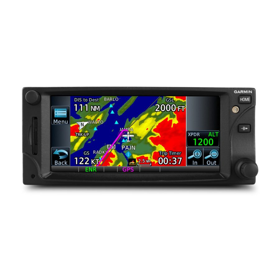
3 GTN CONTROL AND OPERATION 3.1 GTN Controls Figure 3-1. GTN 6XX Control Features (GTN 650 shown) Figure 3-2. GTN 7XX Control Features (GTN 750 shown) 190-01007-B1 GTN 6XX/7XX Part 27 AML STC Maintenance Manual Rev. 1 Page 3-1... -
Page 20: Software Loading
A GTN Software Loader Card may be created using GTN Downloadable Software and an SD card in conjunction with a GTN software application downloaded from the Dealer Resource Center on Garmin’s website. The Dealer Resource Center will allow the technician to choose which software package(s) to load onto the card. -
Page 21: Figure 3-5. Gtn Software Loader Card Formatting
6. Click Next and the window shown in Figure 3-5 will appear. CAUTION In order to create a GTN Software Loader Card, the drive that you select will be completely erased. Figure 3-5. GTN Software Loader Card Formatting 7. Ensure that the correct drive is selected. Click Next to create the card. -
Page 22: Gma 35 Software Loading
2. Insert the GTN Software Loader Card into the GTN 7XX SD card slot (See Section 3.2.1 for instructions on how to create a GTN Software Loader Card). 3. Hold down the HOME key until Garmin is fully lit on the display after power is applied to the GTN 7XX. -
Page 23: Gtn Configuration Mode Overview
1. Remove power from the GTN. 2. Press and hold the HOME key and reapply power to the GTN. 3. Release the HOME key when the display activates and the name ‘Garmin’ appears fully lit on the screen. The first page displayed is the Configuration Mode page, as shown in Figure 3-8. For detailed information regarding how to configure the GTN, refer to the GTN 6XX/7XX Part 27 AML STC Installation Manual, ... -
Page 24: Gtn Software Updates
HOME key and reapplying power to the GTN. Hold the HOME key until the Garmin logo is fully lit on the display. 4. The GTN is now in configuration mode as shown in Figure 3-8. Touch Updates to display the software updates that are available. -
Page 25: System Information
3.3.2 System Information View the System Information page, as shown in Figure 3-10, by touching System Information key on the Configuration Mode page. The System Information page displays the unit type, serial number, and system ID for the GTN. It also contains the software and hardware versions of the Main, I/O, Display, Keypad, LED, GPS/WAAS, COM and NAV boards. - Page 26 Lighting This page allows the user to set the display parameters that affect the backlight and key lighting brightness. Enhanced Lighting This page replaces the 'Lighting' page when enabled under the 'Main System' configuration page. Enhanced Lighting allows the user to set the display parameters that affect the backlight and key lighting brightness.
-
Page 27: Gtn Options Page
3.3.4 GTN Options Page The GTN Options page, shown in Figure 3-12, leads to optional features that can be purchased and enabled. Access the GTN Options page by touching the GTN Options key on the Configuration Mode page. 3.3.4.1 HTAWS Reenablement NOTE This manual only describes the necessary steps to reenable the HTAWS feature for existing installations. -
Page 28: Figure 3-14. Chart Configuration Page
3.3.4.2 ChartView™ Enablement (GTN 7XX Only) The GTN 7XX can display Jeppesen charts using the optional ChartView feature, which must be activated. Complete the following procedure to reenable ChartView. NOTE This manual only describes the necessary steps to reenable the ChartView feature for existing installations. -
Page 29: Figure 3-15. Com Transmit Power Configuration Page
3.3.4.3 COM Transmit Power Enablement (GTN 635/650/750 only) When the optional 16W COM power is configured, the GTN COM will transmit with 16 watts rather than the standard 10 watts. This section describes how to reenable the 16W COM transmit power. NOTE This manual only describes the necessary steps to reenable the 16W COM transmit power for existing... -
Page 30: Gtn Diagnostics Page
3.3.5 GTN Diagnostics Page The GTN Diagnostics page, shown in Figure 3-16, is accessed from the Configuration Mode Home page and is a useful tool for diagnosing issues and troubleshooting problems. Ground checks are also performed using the tools on this page. Figure 3-16. - Page 31 HSDB Ethernet This page displays the status of each HSDB port to be displayed. This page displays whether or not each port is receiving data and displays whether the port is connected or not connected. The communication status of each installed HSDB LRU is also displayed. Main Indicator (Analog) This page displays the CDI connected to the main board (P1001) to be ground checked and allows the interface to be verified.
-
Page 32: Database Updates
GTN. The following describes each database and how the databases are updated. See Table for a summary of the database location and update rate. The GTN Database card, Garmin P/N 010-00900-00, includes the Basemap, Obstacle, SafeTaxi, and Navigation databases. -
Page 33: Troubleshooting
Checkout Log retained in the rotorcraft permanent maintenance records for a list of the interfaced equipment and system configuration data. Section 1.2 If any system fault persists after performing the associated troubleshooting actions, return the GTS Processor to Garmin for service. Refer to Table 4-1. GTN Troubleshooting Guide... - Page 34 Table 4-1. GTN Troubleshooting Guide Problem Possible Cause Corrective Action Incompatible resolver or OBS Resolver won’t calibrate. Check the resolver specifications and wiring. improper connection. GTN resolver input not calibrated correctly. OBS indication on GTN does Check wiring and calibration. not agree with OBS setting.
- Page 35 Table 4-1. GTN Troubleshooting Guide Problem Possible Cause Corrective Action GTN RS-232 port not Check RS-232 port setting for port that device is connected to. configured correctly. Improper setup on the remote Verify the configuration of the other device. device. Device not compatible, or Verify GTN RX is connected to remote device TX and GTN TX is connected to remote device improper connection.
-
Page 36: Gtn Failure Annunciations
4.2 GTN Failure Annunciations If data fields become invalid, the GTN typically annunciates the failures with a large red X, as shown in Figure 4-1 Figure 4-1. Failure Screen GTN 6XX/7XX Part 27 AML STC Maintenance Manual 190-01007-B1 Page 4-4 Rev. -
Page 37: Gtn System Messages
Garmin Product Support. KNOB STUCK - Dual The inner large knob push-key is stuck in the Press the knob to cycle its operation. If the message persists, contact Garmin concentric inner knob is stuck enabled or pressed state. Knob is located on Product Support. - Page 38 3. Verify that the remote OBS switch wiring is correct. Contact Garmin Product Support. 1. Go to the GTN DIAGNOSTICS - DISCRETE INPUTS page in configuration mode and check that the state of the input changes when the CDI switch is pressed and released.
-
Page 39: Table 4-3. Com Alert Troubleshooting Guide
Contact Garmin Product Support. usable. Press the PTT switch to cycle its operation. If the message persists, contact Garmin Product Support. REMOTE KEY STUCK - The COM push-to-talk switch COM push-to-talk key is is stuck in the enabled or Go to the GTN DIAGNOSTICS - DISCRETE INPUTS page in configuration mode and check stuck. - Page 40 Table 4-3. COM Alert Troubleshooting Guide Alert Text Possible Cause Corrective Action COM RADIO - COM Ensure the fan is functioning properly and check for adequate airflow around the unit. The COM is reporting a high overtemp or undervoltage. temperature. Ensure that the COM radio is receiving adequate input voltage (11-33 VDC).
-
Page 41: Table 4-4. Gps/Sbas Alert Troubleshooting Guide
Verify that the center conductor is not shorted to the braid in the coaxial cable. receiver has failed. Check GPS coaxial for electrical Contact Garmin Product Support for assistance. GPS antenna cable may be shorted to short. ground. Check GPS antenna installation, connections, and cable routing. The GPS... -
Page 42: Table 4-5. Vloc/Gs Alert Troubleshooting Guide
Verify that the NAV remote transfer switch wiring is correct. If the problem persists, contact Garmin Product Support. GTN 6XX/7XX Part 27 AML STC Maintenance Manual 190-01007-B1 Page 4-10... -
Page 43: Table 4-6. Remote Transponder Alert Troubleshooting Guide
4.3.1.4 Remote Transponder Related Alerts Table 4-6. Remote Transponder Alert Troubleshooting Guide Alert Text Possible Cause Corrective Action TRANSPONDER 1 - The transponder is reporting a system failure. Refer to the transponder installation manual. Transponder 1 needs service. TRANSPONDER 2 - The transponder is reporting a system failure. -
Page 44: Table 4-7. Traffic Alert Troubleshooting Guide
Verify that the GDL 69 Ethernet ports are enabled. GDL 69. GTN is lost. HSDB data from the GDL 69 can be routed to the GTN through other Garmin LRUs. Ensure that all Garmin LRUs are powered up. GTN 6XX/7XX Part 27 AML STC Maintenance Manual... -
Page 45: Table 4-9. Htaws Alert Troubleshooting Guide
HTAWS - Invalid Terrain The terrain database on the SD Card is not of disappeared. Database sufficient resolution for HTAWS. If the system message persists, contact Garmin Product Support. 190-01007-B1 GTN 6XX/7XX Part 27 AML STC Maintenance Manual Rev. 1 Page 4-13... -
Page 46: Table 4-10. Third-Party Sensor Alert Troubleshooting Guide
4.3.1.8 Third-Party Sensors Related Alerts Table 4-10. Third-Party Sensor Alert Troubleshooting Guide Alert Text Possible Cause Corrective Action If the GTN is not expected to receive pressure altitude, ensure that “Altitude Source Input” is configured for “Not Connected”. Check RS-232 port setting for the port that the device is connected to. DATA SOURCE - Pressure The GTN is configured to receive pressure Verify the configuration of the other device. -
Page 47: Gma 35 Troubleshooting
4.4 GMA 35 Troubleshooting 4.4.1 GMA 35 Failure Annunciations Figure 4-2 depicts a typical failure indication of the GMA 35 audio panel. Figure 4-2. GMA 35 Failure Annunciation 190-01007-B1 GTN 6XX/7XX Part 27 AML STC Maintenance Manual Rev. 1 Page 4-15... -
Page 48: Gma 35 Troubleshooting Guide
Possible Cause Corrective Action AUDIO PANEL - Audio panel Audio panel should be serviced. Return audio panel to Garmin for service. needs service. Audio panel is not powered up. Ensure the audio panel is receiving power and connected to ground. -
Page 49: Equipment Removal And Reinstallation
5 EQUIPMENT REMOVAL AND REINSTALLATION This section describes how to remove and replace equipment associated with this STC. After removal and reinstallation, LRUs must be configured and tested as described in Section 6. CAUTION When removing and/or replacing a GTN, GMA 35, or any other item under the scope of the STC installation, always ensure that the rotorcraft power is off. - Page 50 This page intentionally left blank GTN 6XX/7XX Part 27 AML STC Maintenance Manual 190-01007-B1 Page 5-2 Rev. 1...
-
Page 51: Figure 5-1. Gtn 7Xx Mounting Rack Assembly
Figure 5-1. GTN 7XX Mounting Rack Assembly Sheet 1 of 2 190-01007-B1 GTN 6XX/7XX Part 27 AML STC Maintenance Manual Rev. 1 Page 5-3... - Page 52 Figure 5-1. GTN 7XX Mounting Rack Assembly Sheet 2 of 2 190-01007-B1 GTN 6XX/7XX Part 27 AML STC Maintenance Manual Rev. 1 Page 5-4...
-
Page 53: Figure 5-2. Gtn 6Xx Mounting Rack Assembly
Figure 5-2. GTN 6XX Mounting Rack Assembly Sheet 1 of 2 190-01007-B1 GTN 6XX/7XX Part 27 AML STC Maintenance Manual Rev. 1 Page 5-5... - Page 54 Figure 5-2. GTN 6XX Mounting Rack Assembly Sheet 2 of 2 190-01007-B1 GTN 6XX/7XX Part 27 AML STC Maintenance Manual Rev. 1 Page 5-6...
-
Page 55: Display Of Self-Test Data
5.1.1 Display of Self-Test Data Following normal power-up, the database pages are displayed, followed by the Instrument Panel Self Test page. Touch Continue to display the Instrument Panel Self-Test page. During this time, the electrical outputs are activated and set to the values listed below. Touch Continue to acknowledge the Instrument Panel Self-Test page. -
Page 56: Gma 35
5.2 GMA 35 Removal 1. Remove power from the audio panel. Bell and MD Helicopter Models: This is accomplished by pulling the Audio Panel circuit breaker. Eurocopter Models: Power is removed from the GMA by switching off the avionics master relay. 2. -
Page 57: Figure 5-3. Gma 35 Mounting Rack Assembly Overview
Figure 5-3. GMA 35 Mounting Rack Assembly Overview 190-01007-B1 GTN 6XX/7XX Part 27 AML STC Maintenance Manual Rev. 1 Page 5-9... -
Page 58: Sd Card
5.3 SD Card CAUTION Handle the SD cards carefully. Do not touch the connector edge of the SD card. To replace the data card, complete the following steps: 1. Ensure that the GTN is turned off. 2. Remove the data card by pressing the card until it disengages and then pull the SD card to extract from the unit. -
Page 59: Nav Antenna Cable Splitter
Configuration modules are located within the GTN harness connector backshell (Item 6, Figure 5-4). The 011-00979-03 configuration module kit is recommended for all replacements. Table 5-3. Configuration Module Kit 011-00979-03 (P1001) Figure 5-4 Description Garmin P/N Reference Configuration Module, PCB Board Assembly w/EEPROM 011-02178-00 4-Conductor Harness... -
Page 60: Figure 5-4. Backshell Assembly (Potted Configuration Module)
Removal 1. Disconnect the connector from the GTN backplate assembly. 2. Remove two screws (8) from cover (7) and remove cover. See Figure 5-4 for this step. 3. Unplug the connector from the configuration module (1). 4. Remove the configuration module from the backshell connector. -
Page 61: Gtn Fan
5.8 GTN Fan CAUTION To avoid damage to the GTN, take precautions to prevent Electrostatic Discharge (ESD) when handling the GTN, connectors, fan, and associated wiring. ESD damage can be prevented by touching an object that is of the same electrical potential as the GTN before handling the GTN itself. -
Page 62: Figure 5-5. Fan/Backplate Orientation (Gtn 7Xx Backplate Shown)
Figure 5-5. Fan/Backplate Orientation (GTN 7XX backplate shown) Table 5-4 lists part numbers for the Fan Kit which is used with P1001 only. Table 5-4. Fan Kit Figure 5-6 Ref Description Garmin P/N Fan Cable Assembly, 3 conductor harness 320-00600-00 Pin Contact, Crimp, #22D 336-00021-00... -
Page 63: Figure 5-6. Fan Wiring Installation
Fan Wiring Harness Replacement 1. Strip 0.17” of insulation from each wire prior to crimping. Crimp socket contacts onto each wire of the three-conductor wire harness. Insert newly crimped socket contacts and wires into the appropriate connector housing location as shown in Figure 5-6. 2. - Page 64 This page intentionally left blank GTN 6XX/7XX Part 27 AML STC Maintenance Manual 190-01007-B1 Page 5-16 Rev. 1...
-
Page 65: Return To Service
6 RETURN TO SERVICE This section provides return-to-service procedures to be followed after removal and reinstallation or replacement of equipment comprising part of or interfaced to the GTN 6XX/7XX. After conducting all of the required return-to-service procedures in accordance with this section, the craft may be returned to service. -
Page 66: Gtn Configuration Module
6.2.2 GTN Configuration Module Original Configuration Module Reinstalled No return-to-service procedures are required. New, Repaired, or Exchanged Configuration Module installed Verify GTN configuration settings against the configuration log kept with the rotorcraft permanent record. 6.2.3 GTN Fan Perform the fan check in Section 6.3.8. 6.2.4 GMA 35 (GTN 725/750 only) Original GMA 35 Reinstalled... -
Page 67: Radar Altimeter
6.2.9 Radar Altimeter Original Radar Altimeter Reinstalled No return-to-service procedures are required. New, Repaired, or Exchanged Radar Altimeter Installed Perform interface check in accordance with Section 6.3.9. 6.3 Configuration and Testing Procedures 6.3.1 GTN 6XX/7XX Configuration and Testing This section covers the configuration and checkout procedures that must be completed when a GTN is replaced with an equivalent unit. - Page 68 NOTE If power is lost or the red ‘X’ condition occurs with fewer than three (3) turns, ensure there are no obstructions to the unit fully seating in the rack. Also, the mounting rack may need to be moved aft (toward the pilot) such that the rotorcraft panel does not obstruct the unit from properly engaging in the rack.
-
Page 69: Gma 35 Configuration And Testing
6.3.3 GMA 35 Configuration and Testing The following steps must be performed when replacing a GMA 35 audio panel. 1. Load GMA 35 software per Section 3.2.2. 2. Configure audio panel per Section 6.3.3.1. 3. Perform ground check per Section 6.3.3.2. 6.3.3.1 GMA 35 Audio Panel Configuration (GTN 7XX Only) 6.3.3.1.1 GMA 35 Audio Panel Settings In configuration mode, touch the External Systems key (See... - Page 70 6.3.3.2.2 Failsafe Operation Check NOTE Use of a true mono headset is required for this test to ensure proper wiring even if a stereo jack is provided in the installation. Wiring left channel (tip contact) and right channel (ring contact) backwards will cause failsafe mode not to function with mono headsets. Use of a true mono headset is required for this test (not a stereo headset with a mono/stereo switch because headset manufactures differ on how they accomplish this switching).
- Page 71 6.3.3.2.4 NAV Audio Check Ensure the GMA 35 and each installed NAV receiver is powered on. 1. Tune the NAV receiver to a local VOR station. 2. Ensure the Morse code identifier is being received over the crew headsets. 3. If the audio is not heard, verify the wiring to the audio panel. 4.
-
Page 72: Interfaced Equipment Configuration And Checkout
6.3.3.2.7 Music System Check (if installed) 1. Set the intercom to the ALL mode. 2. Connect a stereo audio source to MUSIC 1 or MUSIC 2. Verify that stereo audio is heard over the Pilot headset position. 3. Tune a station on COM 1 and verify that the sound is muted by active COM 1 audio (break squelch on COM 1 if necessary). -
Page 73: Figure 6-2. Main Indicator (Analog) Configuration Page
6.3.5.1 Navigation Indicator Calibration 6.3.5.1.1 Main Indicator (Analog) Configuration Page Select the Main Indicator (Analog) Configuration Page, shown in Figure 6-2, from the GTN Setup page. This page allows you to calibrate the OBS resolver, configure the CDI key, selected course for GPS and VLOC, as well as the V-Flag state. -
Page 74: Transponder
6.3.5.2 Navigation Indicator Ground Checks (Configuration Mode) 6.3.5.2.1 Main Indicator Check (Analog Only) NOTE If the GTN is interfaced to an electronic HSI/EFIS and the main indicator analog output is not used, this check is not required. NOTE To verify if the indicator is interfaced with the GTN on the main connector (P1001), examine the response of the indicator during the GTN self test upon power-up. -
Page 75: Figure 6-4. Xpdr1 Configuration Page
6.3.6.1 Remote Transponder Configuration A remote transponder can be configured by the GTN via RS- 232 if a transponder is configured for one of the RS-232 ports. To configure the transponder, it must first be selected as present and the type of transponder installed must be specified. To do this, access the Interfaced Equipment page on the GTN Setup page (Figure 3-11). -
Page 76: Traffic Or Weather System
Altitude field. 6.3.7.3 TIS (Garmin GTX 33/330) Interface Check If a Garmin GTX 33/330 transponder has been connected to the GTN as a TIS traffic source, the traffic interface should be verified as described in this section. 1. Select the Traffic Map from the GTN Home page. -
Page 77: Fan Interface Check
6.3.8 Fan Interface Check The fan that is mounted to the GTN backplate should be checked after replacing the fan. With the GTN unit running in normal mode and the fan powered on and running, go to the Home page and touch the Message Queue key. - Page 78 6.4.1.1 HTAWS System Check While on the ground, apply power to the GTN and audio panel following normal power-up procedures. NOTE A 3D GPS position fix is required to conduct the check. 1. Select the Terrain page from the normal mode Home page. 2.
-
Page 79: Appendix Aaircraft Specific Information
APPENDIX A AIRCRAFT SPECIFIC INFORMATION An electronic fillable form is available on the Dealer Resource Center website. Acrobat Reader 8.0 or later is necessary to view and fill out the form. You can download Acrobat Reader by visiting www.adobe.com. GENERAL INFORMATION Date: AIRCRAFT: ROTORCRAFT MODEL:... - Page 80 GTN 6XX/7XX PART 27 CONFIGURATION LOG GTN #1 SYSTEM INFORMATION GTN SOFTWARE VERSIONS Main Board Software: Boot Code: FPGA: Touch Controller Board Software: Boot Code: GPS/WAAS Board Software: NAV Board [N/A] Software: Boot Code: FPGA: COM Board [N/A] Software: Boot Code: FPGA:...
- Page 81 GTN 6XX/7XX PART 27 CONFIGURATION LOG GTN #1 GTN SETUP MENU - CONTINUED HSDB (ETHERNET) CONFIGURATION Port 1: Connected Not Connected Port 3: Connected Not Connected Port 2: Connected Not Connected Port 4: Connected ...
- Page 82 GTN 6XX/7XX PART 27 CONFIGURATION LOG GTN #1 GTN SETUP MENU - CONTINUED ENHANCED LIGHTING CONFIGURATION (IF ENABLED ON MAIN SYSTEM CONFIGURATION PAGE) ENHANCED LIGHTING: [N/A] SOURCE SETTINGS Display Source: Photocell Lighting Bus 1 Keys Source: Photocell Lighting Bus 1 Lighting Bus 2 Photocell: Response Time: Lighting Bus 1: ...
- Page 83 GTN 6XX/7XX PART 27 CONFIGURATION LOG GTN #1 GTN SETUP MENU - CONTINUED AUDIO CONFIGURATION Alert Volume Level: TRAFFIC CONFIGURATION Traffic Intruder Symbol Color: Cyan White GTN Control of Traffic System: Yes No MAIN SYSTEM CONFIGURATION Heading Source Input: ...
- Page 84 GTN 6XX/7XX PART 27 CONFIGURATION LOG GTN #1 GTN SETUP MENU - CONTINUED DISCRETES CONFIGURATION J1001-16: J1001-52: J1001-36: J1001-53: J1001-37: J1001-54: J1001-38: J1001-55: J1001-39: J1001-56: J1002-01: J1001-57: J1002-10: J1001-71: J1002-11: J1001-72: J1005-33*: J1001-73: J1005-53*: J1001-74: J1005-54*: J1001-75: J1001-14: J1002-76: J1001-15: J1002-03: J1001-33: J1002-12:...
- Page 85 GTN 6XX/7XX PART 27 CONFIGURATION LOG GTN #1 GTN OPTIONS MENU TERRAIN CONFIGURATION Terrain Mode: HTerrain Proximity HTAWS HTAWS Configuration AIRPORT CRITERIA Runway Surface: Any Hard Only Hard/Soft Water Minimum Runway Length: CHARTS None ...
- Page 86 GTN 6XX/7XX PART 27 CONFIGURATION LOG GTN #2 SYSTEM INFORMATION GTN SOFTWARE VERSIONS Main Board Software: Boot Code: FPGA: Touch Controller Board Software: Boot Code: GPS/WAAS Board Software: NAV Board [N/A] Software: Boot Code: FPGA: COM Board [N/A] Software: Boot Code: FPGA:...
- Page 87 GTN 6XX/7XX PART 27 CONFIGURATION LOG GTN #2 GTN SETUP MENU - CONTINUED HSDB (ETHERNET) CONFIGURATION Port 1: Connected Not Connected Port 3: Connected Not Connected Port 2: Connected Not Connected Port 4: Connected ...
- Page 88 GTN 6XX/7XX PART 27 CONFIGURATION LOG GTN #2 GTN SETUP MENU - CONTINUED ENHANCED LIGHTING CONFIGURATION (IF ENABLED ON MAIN SYSTEM CONFIGURATION PAGE) ENHANCED LIGHTING: [N/A] SOURCE SETTINGS Display Source: Photocell Lighting Bus 1 Keys Source: Photocell Lighting Bus 1 Lighting Bus 2 Photocell: Response Time: Lighting Bus 1: ...
- Page 89 GTN 6XX/7XX PART 27 CONFIGURATION LOG GTN #2 GTN SETUP MENU - CONTINUED AUDIO CONFIGURATION Alert Volume Level: TRAFFIC CONFIGURATION Traffic Intruder Symbol Color: Cyan White GTN Control of Traffic System: Yes No MAIN SYSTEM CONFIGURATION Heading Source Input: ...
- Page 90 GTN 6XX/7XX PART 27 CONFIGURATION LOG GTN #2 GTN SETUP MENU - CONTINUED DISCRETES CONFIGURATION J1001-16: J1001-52: J1001-36: J1001-53: J1001-37: J1001-54: J1001-38: J1001-55: J1001-39: J1001-56: J1002-01: J1001-57: J1002-10: J1001-71: J1002-11: J1001-72: J1005-33*: J1001-73: J1005-53*: J1001-74: J1005-54*: J1001-75: J1001-14: J1002-76: J1001-15: J1002-03: J1001-33: J1002-12:...
- Page 91 GTN 6XX/7XX PART 27 CONFIGURATION LOG GTN #2 GTN OPTIONS MENU TERRAIN CONFIGURATION Terrain Mode: HTerrain Proximity HTAWS HTAWS Configuration AIRPORT CRITERIA Runway Surface: Any Hard Only Hard/Soft Water Minimum Runway Length: CHARTS None ...
- Page 92 GTN 6XX/7XX PART 27 CONFIGURATION LOG GMA 35 AUDIO PANEL CONFIGURATION [N/A] Software Version: AUDIO PANEL CONFIGURATION INTERCOM True False Mute PASS to CREW intercom during alerts True False Mute PASS to CREW intercom during selected audio ...
- Page 93 GTN 6XX/7XX PART 27 CONFIGURATION LOG GMA 35 AUDIO PANEL CONFIGURATION - CONTINUED AUDIO PANEL CONNECTED RADIOS Present Not Present COM 2: Present Not Present COM 3: Present Not Present NAV 1: Present ...
- Page 94 Installed: Yes No GTN #1 GTN #2 GTN Interface: Location (Flight Station, Lateral Arm): Notes: GARMIN AUDIO PANEL Installed: Yes No GTN #1 GTN #2 GTN Interface: Location (Flight Station, Lateral Arm):...
- Page 95 GTN Interfaced Equipment List - CONTINUED GARMIN TRANSPONDER #1 Installed: Yes No GTN #1 GTN #2 GTN Interface: Location (Flight Station, Lateral Arm): Notes: GARMIN TRANSPONDER #2 Installed: Yes No GTN #1 GTN #2...
- Page 96 GTN Interfaced Equipment List - CONTINUED GDU 620 Installed: Yes No GTN #1 GTN #2 GTN Interface: Location (Flight Station, Lateral Arm): Notes: GI 102( )/106( ) Installed: Yes No GTN #1 GTN #2 GTN Interface: Location (Flight Station, Lateral Arm): Notes:...
- Page 97 GTN Interfaced Equipment List - CONTINUED GSR 56 Installed: Yes No GTN #1 GTN #2 GTN Interface: Location (Flight Station, Lateral Arm): Notes: GTS 8X5 Installed: Yes No GTN #1 GTN #2 GTN Interface: Location (Flight Station, Lateral Arm): Notes:...
-
Page 98: Audio Panel
GTN Interfaced to Other Equipment List The purpose of this list is to document other equipment that is interfaced with the GTN. Use the following guidance when filling out these tables: Installed?: Check “Yes” if the equipment is installed in the aircraft and interfaced to the GTN. If the equipment is not installed in the aircraft, check “No.”... - Page 99 GTN Interfaced to Other Equipment List - CONTINUED IRU/AHRS Installed: Yes No Covered by STC?: Yes No GTN Interface: GTN #1 GTN #2 Location (Flight Station, Lateral Arm): Notes: WEATHER, TRAFFIC AND TERRAIN Installed: Yes No Covered by STC?: ...
- Page 100 GTN Interfaced to Other Equipment List - CONTINUED CDI/HSI SOURCE SELECTION ANNUNCIATOR Installed: Yes No Covered by STC?: Yes No GTN Interface: GTN #1 GTN #2 Location (Flight Station, Lateral Arm): Notes: HTAWS ANNUNCIATOR PANEL Installed: ...
- Page 101 GMA 35 Interfaces The purpose of this list is to document other equipment that is interfaced with the GTN. Use the following guidance when filling out these tables: Installed?: Check “Yes” if the equipment is installed in the aircraft and interfaced to the GTN. If the equipment is not installed in the aircraft, check “No.”...
- Page 102 GMA 35 Interfaces - CONTINUED COM RADIO #2 Installed: Yes No Covered by STC?: Yes No Location (Flight Station, Lateral Arm) Notes: NAV RADIO #1 Installed: Yes No Covered by STC?: Yes No Location (Flight Station, Lateral Arm) Notes: NAV RADIO #2...
- Page 103 GMA 35 INTERFACES - CONTINUED TRAFFIC ADIVSORY SYSTEM Installed: Yes No Covered by STC?: Yes No Location (Flight Station, Lateral Arm) Notes: POTS TELEPHONE Installed: Yes No Covered by STC?: Yes No Location (Flight Station, Lateral Arm) Notes: GDU 620...
- Page 104 GMA 35 INTERFACES - CONTINUED GTN #1 Installed: Yes No Covered by STC?: Yes No Location (Flight Station, Lateral Arm) Notes: GTN #2 Installed: Yes No Covered by STC?: Yes No Location (Flight Station, Lateral Arm) Notes: GDL 69/69A Installed: ...