
Related Manuals for HP ProCurve 2520G-PoE Series


Summary of Contents for HP ProCurve 2520G-PoE Series
- Page 1 HP ProCurve 2520G-PoE Switches Installation and Getting Started Guide Power over Ethernet...
- Page 3 HP ProCurve 2520G-PoE Switches Installation and Getting Started Guide...
- Page 4 Applicable Products accompanying such products and services. Nothing herein should be construed as constituting an additional warranty. HP shall not be liable for technical or editorial errors or omissions contained herein. HP ProCurve 2520G-8-PoE Switch (J9298A)
-
Page 5: Table Of Contents
Contents 1 Introducing the Switch Front of the Switch ..........1-3 Network Ports . - Page 6 6. Installing or Removing mini-GBICs ......2-18 Installing the mini-GBICs: ....... . 2-18 Removing the mini-GBICs .
- Page 7 HP Customer Support Services ........4-13 Before Calling Support ........4-13 A Specifications Switch Specifications .
- Page 8 Japan ........... . . B-8 Korea .
-
Page 9: Introducing The Switch
Introducing the Switch The HP ProCurve 2520G-PoE Switches are multiport switches that can be used to build high-performance switched workgroup networks. These switches are store-and-forward devices that offer low latency for high-speed networking. The 2520G-PoE switches also support Power over Ethernet (PoE) technologies. - Page 10 1000-BX Fiber (single mode) www.hp.com/go/procurve/faqs For supported transceivers, see . HP ProCurve Mini- GBICs and SFPs have links to a list of supported products (first question in the "General product information" category). For technical details of cabling and technologies see “Cabling and Technology Informa-...
-
Page 11: Front Of The Switch
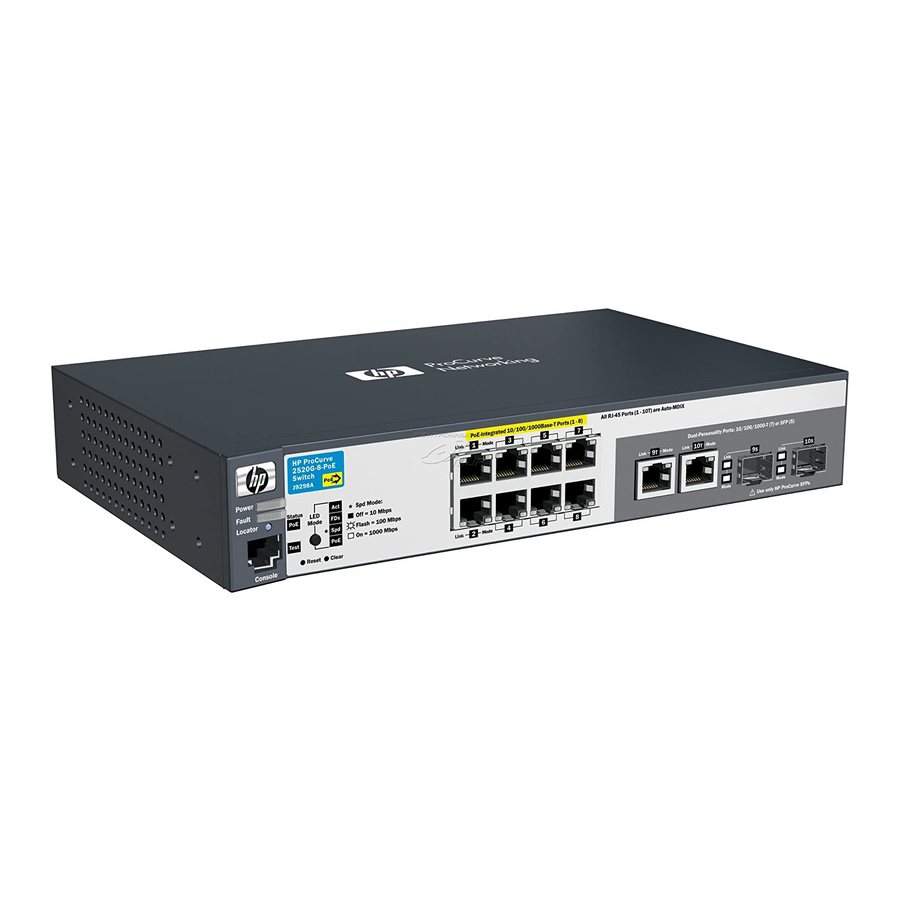
Introducing the Switch Front of the Switch Front of the Switch Power, Test and Status HP ProCurve 2520G-8-PoE Switch (J9298A) Switch port LEDs Fault, and LEDs Locator LEDs Console Reset and Clear LED Mode select button Dual-personality ports 10/100/1000Base-T RJ-45 ports... -
Page 12: Leds
Introducing the Switch Front of the Switch LEDs On the 2520G-PoE switches, there are three groupings of LEDs: ■ switch status LEDs (Table 1-2) port LEDs (Table 1-3) ■ ■ Port LED Mode indicator LEDs (near the selector button) (Table 1-4) Table 1-2. - Page 13 Introducing the Switch Front of the Switch Switch LEDs State Meaning Test The normal operational state; the switch is not undergoing self test. (green/orange) On green The switch self test and initialization are in progress after the switch has been power cycled or reset. The switch is not operational until this LED goes off.
-
Page 14: Port Leds
Introducing the Switch Front of the Switch Port LEDs The port LEDs provide information about the individual switch ports. Table 1-3. Port LEDs Switch LEDs State Meaning Port LEDs Link The port is enabled and receiving a link indication from the connected device. -
Page 15: Led Mode Select Button And Indicator Leds
Introducing the Switch Front of the Switch LED Mode Select Button and Indicator LEDs To optimize the amount of information that can be displayed for each of the switch ports in the limited space available, the 2520G-PoE switches use multiple-display LEDs for each port. Mode LED Link LED The 2520G-PoE switches, have two... -
Page 16: Reset Button
Introducing the Switch Front of the Switch Reset Button This button is for: ■ Resetting the switch - When the switch is powered on. This action clears any temporary error conditions that may have occurred and executes the switch self test. Restoring Factory Default Configuration - When pressed with the ■... -
Page 17: Back Of The Switch
Introducing the Switch Back of the Switch Back of the Switch HP ProCurve 2520G-8-PoE Switch (J9298A) DC power connector HP ProCurve 2520G-24-PoE Switch (J9299A) AC power connector Power Connector The Switch 2520G-24-PoE does not have a power switch; it is powered on when connected to an active AC power source. -
Page 18: Switch Features
15.4W per port to power IP phones, wireless access points, Web cameras, and more. For more information, see the PoE Planning and Implementation Guide, which is on the ProCurve Web site at www.hp.com/go/procurve/manuals. ■ The switches support some pre-standard PoE devices. However, the use of a cross-over cable may be required. -
Page 19: Save Power Mode
Support for many advanced features to enhance network performance— for a description, see the Management and Configuration Guide, which is on the ProCurve Web site at www.hp.com/go/procurve/manuals. (You may want to bookmark this Web page for easy access in the future.) Save Power Mode A Save Power mode feature can be configured through the console. -
Page 21: Installing The Switch
• four 5/8-inch number 12-24 screws to • four rubber feet attach the switch to a rack • cable tie for power cord • four rubber feet For wall mounting the Switch 2520G-8-PoE. For rack mounting, an optional bracket kit, 5070-6570, is available. Visit www.hp.com/go/procurve-parts. - Page 22 Installing the Switch Included Parts Switch 2520G-24-PoE AC power cords, one of the following: ■ Australia/New Zealand 8121-0833 China 8120-8377 Continental Europe 8120-6802 Denmark 8120-6806 India 8121-0772 Israel 8120-6799 Japan 8120-6804 South Africa 8120-6808 Switzerland 8120-6807 Thailand 8121-0667 Taiwan 8121-0964 United Kingdom/Hong Kong/Singapore 8120-8709 United States/Canada/Mexico...
-
Page 23: Installation Precautions
Installing the Switch Included Parts Installation Precautions W A R N I N G The rack or cabinet should be adequately secured to prevent it ■ from becoming unstable and/or falling over. Devices installed in a rack or cabinet should be mounted as low as possible, with the heaviest devices at the bottom and progressively lighter devices installed above. -
Page 24: Installation Procedures
Installing the Switch Installation Procedures Installation Procedures These steps summarize your switch installation. The rest of this chapter provides details on these steps. Prepare the installation site (page 2-5). Make sure the physical environment into which you will be installing the switch is properly prepared, including having the correct network cabling ready to connect to the switch and having an appropriate location for the switch. -
Page 25: Prepare The Installation Site
Installing the Switch Installation Procedures 1. Prepare the Installation Site ■ Cabling Infrastructure - Ensure the cabling infrastructure meets the necessary network specifications. See appendix A, “Cabling and Technology Information Specifications” for more information: Installation Location - Before installing the switch, plan its location and ■... -
Page 26: Verify The Switch Passes Self Test
Installing the Switch Installation Procedures 2. Verify the Switch Passes Self Test Before mounting the switch in its network location, you should first verify it is working properly by plugging it into a power source and verifying it passes its self test. For the Switch 2520G-24-PoE, connect the power cord supplied with the switch to the power connector on the back of the switch, and then into a properly grounded electrical outlet. - Page 27 Installing the Switch Installation Procedures The switch automatically adjusts to any voltage between 100-127 or 200-240 volts and either 50 or 60 Hz. There are no voltage range settings required. The Switch 2520G-8-PoE also does not have a power switch. It is powered on when the external AC/DC power adapter is connected to the switch and the adapter power cord to a power source.
-
Page 28: Led Behavior
Installing the Switch Installation Procedures LED Behavior During the self test: • Initially, all the switch and port LEDs are on. Most of the LEDs go off and then may come on again during phases of the self test. • For the duration of the self test, the Test LED stays on. -
Page 29: Rack Mounting The Switch 2520G-24-Poe
Installing the Switch Installation Procedures W A R N I N G For safe operation, please read the mounting precautions on page 2-3, before mounting a switch. E q u i p m e n t The 12-24 screws supplied with the switch are the correct threading for C a b i n e t standard EIA/TIA open 19-inch racks. - Page 30 Installing the Switch Installation Procedures Hold the switch with attached brackets up to the rack and move it vertically until rack holes line up with the bracket holes, then insert and tighten the four number 12-24 screws holding the brackets to the rack. Install 12-24 screws Figure 2-4.
-
Page 31: Rack Mounting The Switch 2520G-8-Poe
Installing the Switch Installation Procedures Rack Mounting the Switch 2520G-8-PoE N o t e Requires optional mounting bracket kit (not included). Use a #1 Phillips (cross-head) screwdriver and attach the mounting brackets to the switch with the included 8-mm M4 screws. 8 mm M4 screws Figure 2-5. - Page 32 Installing the Switch Installation Procedures Hold the switch with attached brackets up to the rack and move it vertically until rack holes line up with the bracket holes, then insert and tighten the four number 12-24 screws holding the brackets to the rack. Install 12-24 screws Figure 2-6.
-
Page 33: Wall Or Under-Table Mounting
Installing the Switch Installation Procedures Wall or Under-Table Mounting You can mount the switch on a wall with either the front or rear panel facing W A R N I N G For safe operation, do not install the switch with side ventilation or fan ducts facing up or down. -
Page 34: Horizontal Surface Mounting
Installing the Switch Installation Procedures RJ-45 Ports Wall 5/8-inch wood screws Figure 2-8. Wall Mounting the Switch 2520G-8-PoE Horizontal Surface Mounting Place the switch on a table or other horizontal surface. The switch comes with rubber feet in the accessory kit that can be used to help keep the switch from sliding on the surface. -
Page 35: Using A Kensington Security Cable
Installing the Switch Installation Procedures Figure 2-9. Horizontal Surface Mounting Using a Kensington Security Cable To prevent unauthorized removal of the Switch 2520G-8-PoE, you can use a Kensington Slim MicroSaver security cable (not included) to attach the switch to an immovable object. Figure 2-10. - Page 36 Installing the Switch Installation Procedures Re-check the LEDs during self test. See “LED Behavior” on page 2-8. Figure 2-11. Connecting the power cord on the Switch 2520G-24-PoE For the Switch 2520G-8-PoE, use the included cable tie to secure the power cord to the switch. cable tie Figure 2-12.
-
Page 37: Connect The Network Cables
Installing the Switch Installation Procedures 5. Connect the Network Cables Connect the network cables, described under “Cabling Infrastructure” (page 2-5), from the network devices or your patch panels to the fixed RJ-45 ports on the switch or to any mini-GBICs you have installed in the switch. Using the RJ-45 Connectors To connect: Push the RJ-45 plug into the RJ-45... -
Page 38: Installing Or Removing Mini-Gbics
C a u t i o n Use only supported genuine HP ProCurve mini-GBICs with your switch. Non- ProCurve mini-GBICs are not supported, and their use may result in product malfunction. Should you require additional HP ProCurve mini-GBICs, contact your ProCurve Networking Sales and Service Office or authorized dealer. -
Page 39: Removing The Mini-Gbics
Installing the Switch Installation Procedures Figure 2-14. Installing a mini-GBIC (SFP) Removing the mini-GBICs N o t e You should disconnect the network cable from the mini-GBIC before removing it from the switch. Depending on when you purchased your ProCurve mini-GBIC, it may have either of three different release mechanisms: a plastic tab on the bottom of the mini-GBIC, a plastic collar around the mini-GBIC, or a wire bail. -
Page 40: Optional) Connect A Console To The Switch
3, “Configuring the Switch”, in the Management and Configuration Guide, which is on the ProCurve Web site at www.hp.com/ go/procurve/manuals. The 2520G-PoE switches can simultaneously support one out-of-band console session through the Console Port and in-band Telnet console sessions. -
Page 41: Direct Console Access
If you want to continue with console management of the switch at this time, see chapter 3, “Getting Started With Switch Configuration” for some basic configuration steps. For more detailed information, refer to the Management and Configuration Guide, which is on the ProCurve Web site at www.hp.com/ go/procurve/manuals. 2-21... -
Page 42: Sample Network Topologies
Sample Network Topologies Sample Network Topologies This section shows a few sample network topologies for implementing the 2520G-PoE switches. For more topology information, see the ProCurve networking products Web site, www.hp.com/go/procurve. As a Desktop Switch Implementing PoE Server with Gigabit... -
Page 43: As A Segment Switch Implementing Poe
Installing the Switch Sample Network Topologies As shown in the above illustration, the IP telephones can be connected in line, that is, between the switch and the end device, in this case a PC. The IP telephones have two ports, one in and one out. Therefore the phone receives voice and power from the switch and the PC can send and receive data through the phone to the switch. - Page 44 Installing the Switch Sample Network Topologies The 2520G-PoE switches also work well as segment switches. That is, with their high performance, they can be used for interconnecting network segments—simply connect the network devices that form those segments to the 2520G-PoE switches. In the illustration above, 2520G-PoE switches with PCs, printers, and local servers attached, are both connected to a non-PoE switch.
-
Page 45: Stacking The Switch
IP address. The management includes Telnet access and Web browser interface access to the Commander and to each Member switch through the Commander. For more information on stacking your switch, see the Management and www.hp.com/go/ Configuration Guide, which is on the ProCurve Web site at procurve/manuals. 2-25... -
Page 47: Configuring The Switch
For more information on using the switch console and the Web browser interface, please see the Management and Configuration Guide, which is on the ProCurve Web site at www.hp.com/go/procurve/manuals. Recommended Minimal Configuration In the factory default configuration, the switch has no IP (Internet Protocol) address and subnet mask, and no passwords. -
Page 48: Using The Console Setup Screen
Configuring the Switch Recommended Minimal Configuration Using the Console Setup Screen The quickest and easiest way to minimally configure the switch for management and password protection in your network is to use a direct console connection to the switch, start a console session, and access the Switch Setup screen. -
Page 49: Where To Go From Here
Configuring the Switch Recommended Minimal Configuration Here is some information on the fields in the Setup screen. For more information on these fields, see the Management and Configuration Guide: Parameter Default System Name blank Optional; up to 25 characters, including spaces System Contact blank Optional;... - Page 50 Configuring the Switch Recommended Minimal Configuration To Recover from a Lost Manager Password: If you cannot start a console session at the manager level because of a lost Manager password, you can clear all passwords and user names by getting physical access to the switch and pressing and holding the Clear button for a full second.
-
Page 51: Using The Ip Address For Remote Switch Management
Configuring the Switch Using the IP Address for Remote Switch Management Using the IP Address for Remote Switch Management With your switch, you can use the switch’s IP address to manage the switch from any PC that is on the same subnet as the switch. You can use either a Telnet session or a standard Web browser to manage the switch. -
Page 53: Troubleshooting
Troubleshooting This chapter describes how to troubleshoot your ProCurve 2520G-PoE Switches. This document describes troubleshooting mostly from a hardware perspective. You can perform more in-depth troubleshooting on these devices using the software tools available with the switches, including the full- featured console interface, the built-in Web browser interface, and ProCurve Manager, the SNMP-based network management tool. - Page 54 Sample topologies are shown at the end of chapter 2 in this book, and some topology configuration guidelines can be found online at the ProCurve Web site, www.hp.com/go/procurve. In addition, you should make sure that your network topology contains no data path loops.
- Page 55 Management and Configuration Guide. For more information on possible network problems and their solutions, refer to the technical note “Troubleshooting LAN Performance and Intermittent Connectivity Problems”, which can be found on the ProCurve Web site, www.hp.com/go/procurve, in the Reference Library section, A-Z Index.
-
Page 56: Diagnosing With The Leds
Troubleshooting Diagnosing with the LEDs Diagnosing with the LEDs Table 4-1 shows LED patterns on the switch that indicate problem conditions for general switch operation troubleshooting. Table 4-2 shows LED patterns that indicate problem conditions for PoE troubleshooting. LED patterns for General Switch Troubleshooting Check in the table for the LED pattern you see on your switch. -
Page 57: Diagnostic Tips
If the power source and power cord are OK and this condition persists, the switch power supply may have failed. Call your ProCurve Networking authorized network reseller, or use the electronic support services from HP to get assistance. See the Software License, Warranty and Support booklet for more information. - Page 58 Troubleshooting Diagnosing with the LEDs Problem Solution ➏ The network Try the following procedures: connection is not • For the indicated port, verify that both ends of the cabling, at the switch and the working connected device, are connected properly. properly.
- Page 59 For software troubleshooting tips, see the chapter “Troubleshooting” in the and Configuration Guide , which is on the ProCurve Web site at www.hp.com/go/ procurve/manuals. Ensure also, that the device at the other end of the connection is indicating a good link to the switch.
-
Page 60: Led Patterns For Poe Troubleshooting
Troubleshooting Diagnosing with the LEDs LED Patterns for PoE Troubleshooting If the PoE Status LED is flashing, that indicates a problem with the delivery of PoE power out one or more switch ports. Press the LED Mode button to put the switch into PoE mode and the port LEDs will show which ports are experiencing the problem. -
Page 61: Proactive Networking
Troubleshooting Proactive Networking Proactive Networking The ProCurve 2520G-PoE Switches have built-in management capabilities that proactively help you manage your network including: finding and helping you fix the most common network error conditions ■ (for example, faulty network cabling, and non-standard network topologies) ■... -
Page 62: Hardware Diagnostic Tests
Troubleshooting Hardware Diagnostic Tests Hardware Diagnostic Tests Testing the Switch by Resetting It If you believe the switch is not operating correctly, you can reset the switch to test its circuitry and operating code. To reset a switch, either: ■ unplug and plug in the power cord (power cycling) ■... -
Page 63: Testing Twisted-Pair Cabling
Telnet connection, or from the switch’s Web browser interface. For more information, see the Management and Configuration Guide, which is on the ProCurve Web site at www.hp.com/ go/procurve/manuals. Testing End-to-End Network Communications Both the switch and the cabling can be tested by running an end-to-end communications test—a test that sends known data from one network device... -
Page 64: Restoring The Factory Default Configuration
For more information on this command, see the Management and Configuration Guide, which is on the ProCurve Web site at www.hp.com/go/procurve/manuals. You can restore the factory default configuration either on the switch itself, or through the switch console. -
Page 65: Downloading New Switch Software
Additionally, your HP-authorized network reseller can provide you with assistance, both with services that they offer and with services offered by HP. Before Calling Support Before calling your networking dealer or HP Support, to make the support... -
Page 67: Switch Specifications
Specifications Switch Specifications Physical Width Depth Height Weight 2520G-8-PoE (J9298A) 25.4 cm (10 in) 16.5 cm (6.5 in) 4.4 cm (1.73 in) 0.91 kg (2.01 lbs) 2520G-24-PoE (J9299A) 44.3 cm (17.4 in) 25.1 cm (9.88 in) 4.4 cm (1.73 in) 3.27 kg (7.21 lbs) Electrical AC voltage... -
Page 68: Btu Ratings
Specifications Switch Specifications BTU Ratings Switch Model Combined BTU 2520G-8-PoE 2520G-24-PoE Includes switch and maximum number of PoE powered devices connected to the switch at 15.4 watts. Acoustics 2520G-8-PoE (J9298A) No fans. 2520G-24-PoE (J9299A) Geraeuschemission LpA=28.3 dB am fiktiven Arbeitsplatz nach DIN 45635 T.19 Noise Emission LpA=28.3 dB at virtual workspace according to DIN 45635 T.19... -
Page 69: Standards
Specifications Standards Standards Table A-1. Technology Standards and Safety Compliance Laser safety information Technology Compatible with these IEEE EN/IEC standards standard ("mini-GBIC") Lasers compliance 10-T IEEE 802.3 10BASE-T, 100-TX IEEE 802.3u 100BASE-TX, 1000-T IEEE 802.3ab 1000BASE-T 100-FX IEEE 802.3u 100BASE-FX EN/IEC 60825 Class 1 Laser Product Laser Klasse 1... -
Page 70: Cabling And Technology Information Specifications
Specifications Cabling and Technology Information Specifications Cabling and Technology Information Specifications Table A-2. Cabling Specifications 10 Mbps Operation Category 3, 4 or 5, 100-ohm unshielded twisted-pair (UTP) or shielded twisted-pair (STP) cable, complying with IEEE 802.3 10BASE-T specifications. 100 Mbps Operation Category 5, 100-ohm UTP or STP cable, complying with IEEE Twisted-pair copper 802.3u 100BASE-TX specifications. -
Page 71: Technology Distance Specifications
Specifications Cabling and Technology Information Specifications Technology Distance Specifications Table A-3. Technology Distance Specifications Technology Supported cable type Multimode fiber Supported distances modal bandwidth 100-FX multimode fiber up to 2,000 meters 100-BX single mode fiber 0.5 - 10,000 meters 1000-T twisted-pair copper up to 100 meters 1000-SX... -
Page 72: Mode Conditioning Patch Cord
Specifications Mode Conditioning Patch Cord Mode Conditioning Patch Cord The following information applies to installations in which multimode fiber- optic cables are connected to a Gigabit-LX port. Multimode cable has a design characteristic called “Differential Mode Delay”, which requires the transmission signals be “conditioned”... - Page 73 Specifications Mode Conditioning Patch Cord Gigabit-LX port To network multimode Mode Conditioning cabling Patch Cord Single mode section plugs into Tx The multimode cable in the patch cord port on Gigabit-LX Transceiver or must match the characteristics of your Gigabit-LX mini-GBIC network cable Figure A-1.
-
Page 74: Twisted-Pair Cable/Connector Pin-Outs
Specifications Twisted-Pair Cable/Connector Pin-Outs Twisted-Pair Cable/Connector Pin-Outs The Auto-MDIX Feature: In the default configuration, “Auto”, the fixed 10/ 100/1000Base-T ports on the 2520G-PoE switches all automatically detect the type of port on the connected device and operate as either an MDI or MDI-X port, whichever is appropriate. - Page 75 Specifications Twisted-Pair Cable/Connector Pin-Outs For 100 Mbps connections to the ports, use 100-ohm Category 5 UTP or ■ STP cable only, as supported by the IEEE 802.3u Type 100Base-TX standard. ■ For 1000 Mbps connections, 100-ohm Category 5e or better cabling is recommended.
-
Page 76: Straight-Through Twisted-Pair Cable For 10 Mbps Or 100 Mbps Network Connections
Specifications Twisted-Pair Cable/Connector Pin-Outs Straight-through Twisted-Pair Cable for 10 Mbps or 100 Mbps Network Connections Because of the Auto-MDIX operation of the 10/100 ports on the switch, for all network connections, to PCs, servers or other end nodes, or to hubs or other switches, you can use straight-through cables. -
Page 77: Crossover Twisted-Pair Cable For 10 Mbps Or 100 Mbps Network Connection
Specifications Twisted-Pair Cable/Connector Pin-Outs Crossover Twisted-Pair Cable for 10 Mbps or 100 Mbps Network Connection The Auto-MDIX operation of the 10/100 ports on the switch also allows you to use crossover cables for all network connections, to PCs, servers or other end nodes, or to hubs or other switches. -
Page 78: Straight-Through Twisted-Pair Cable For 1000 Mbps Network Connections
Specifications Twisted-Pair Cable/Connector Pin-Outs Straight-Through Twisted-Pair Cable for 1000 Mbps Network Connections 1000Base-T connections require that all four pairs of wires be connected. Cable Diagram N o t e Pins 1 and 2 on connector “A” must be wired as a twisted pair to pins 1 and 2 on connector “B”. -
Page 79: B Safety And Emc Regulatory Statements
Safety and EMC Regulatory Statements Safety Information Documentation reference symbol. If the product is marked with this symbol, refer to the product documentation to get more information about the product. WARNING A WARNING in the manual denotes a hazard that can cause injury or death. - Page 80 Safety and EMC Regulatory Statements Informations concernant la sécurité Informations concernant la sécurité Symbole de référence à la documentation. Si le produit est marqué de ce symbole, reportez-vous à la documentation du produit afin d'obtenir des informations plus détaillées. WARNING Dans la documentation, un WARNING indique un danger susceptible d'entraîner des dommages corporels ou la mort.
-
Page 81: Hinweise Zur Sicherheit
Safety and EMC Regulatory Statements Hinweise zur Sicherheit Hinweise zur Sicherheit Symbol für Dokumentationsverweis. Wenn das Produkt mit diesem Symbol markiert ist, schlagen Sie bitte in der Produktdokumentation nach, um mehr Informationen über das Produkt zu erhalten. WARNING Eine WARNING in der Dokumentation symbolisiert eine Gefahr, die Verletzungen oder sogar Todesfälle verursachen kann. -
Page 82: Considerazioni Sulla Sicurezza
Safety and EMC Regulatory Statements Considerazioni sulla sicurezza Considerazioni sulla sicurezza Simbolo di riferimento alla documentazione. Se il prodotto è contrassegnato da questo simbolo, fare riferimento alla documen- tazione sul prodotto per ulteriori informazioni su di esso. WARNING La dicitura WARNINGdenota un pericolo che può causare lesioni o morte. -
Page 83: Consideraciones Sobre Seguridad
Safety and EMC Regulatory Statements Consideraciones sobre seguridad Consideraciones sobre seguridad Símbolo de referencia a la documentación. Si el producto va marcado con este símbolo, consultar la documentación del producto a fin de obtener mayor información sobre el producto. WARNING Una WARNING en la documentación señala un riesgo que podría resultar en lesiones o la muerte. -
Page 84: Safety Information
Safety and EMC Regulatory Statements Safety Information (Japan) Safety Information (Japan) J a p a n P o w e r C o r d W a r n i n g... - Page 85 Safety and EMC Regulatory Statements Safety Information (China) Safety Information (China)
-
Page 86: Emc Regulatory Statements
Safety and EMC Regulatory Statements EMC Regulatory Statements EMC Regulatory Statements U.S.A. FCC Class A This equipment has been tested and found to comply with the limits for a Class A digital device, pursuant to Part 15 of the FCC Rules. These limits are designed to provide reasonable protection against interference when the equipment is operated in a commercial environment. -
Page 87: Korea
Safety and EMC Regulatory Statements EMC Regulatory Statements Korea Taiwan... -
Page 88: European Community
Safety and EMC Regulatory Statements EMC Regulatory Statements European Community B-10... - Page 89 Safety and EMC Regulatory Statements EMC Regulatory Statements B-11...
-
Page 91: D Recycle Statements
Recycle Statements Waste Electrical and Electronic Equipment (WEEE) Statements Disposal of Waste Equipment by Users in Private Household in the European Union This symbol on the product or on its packaging indicates that this product must not be disposed of with your other household waste. - Page 92 Recycle Statements Waste Electrical and Electronic Equipment (WEEE) Statements Laitteiden hävittäminen kotitalouksissa Euroopan unionin alueella Jos tuotteessa tai sen pakkauksessa on tämä merkki, tuotetta ei saa hävittää kotitalousjätteiden mukana. Tällöin hävitettävä laite on toimitettava sähkölaitteiden ja elektronisten laitteiden kierrätyspisteeseen. Hävitettävien laitteiden erillinen käsittely ja kierrätys auttavat säästämään luonnonvaroja ja varmista- maan, että...
- Page 93 Recycle Statements Waste Electrical and Electronic Equipment (WEEE) Statements Smaltimento delle apparecchiature da parte di privati nel territorio dell'Unione Europea Questo simbolo presente sul prodotto o sulla sua confezione indica che il prodotto non può essere smaltito insieme ai rifiuti domestici. È responsabilità dell'utente smaltire le apparecchiature consegnan- dole presso un punto di raccolta designato al riciclo e allo smaltimento di apparecchiature elettriche ed elettroniche.
- Page 94 Para obter mais informações sobre locais que reciclam esse tipo de material, entre em contato com o escritório da HP em sua cidade, com o serviço de coleta de lixo ou com a loja em que o produto foi adquirido.
-
Page 95: Index
… A-11 AC power connector cables, twisted-pair location on back of switch … 1-9 HP Auto-MDIX feature … A-8 acoustic specifications … A-2 wiring rules … A-8 auto MDI/MDI-X operation … A-10, A-12 cables, twisted-pair connector pin-outs … A-8 HP Auto-MDIX feature …... - Page 96 … 4-10 horizontal surface checking the console messages … 4-10 mounting switch on … 2-14 checking the LEDs … 4-10 HP Auto-MDIX end-to-end connectivity … 4-11 feature description … A-8 testing the switch only … 4-10 testing twisted-pair cabling … 4-11 downloading new switch software …...
- Page 97 … 2-15 horizontal surface mounting … 2-14 location considerations … 2-5 network cables network cable requirements … 2-5 HP Auto-MDIX feature … A-8 precautions … 2-3 required types … 2-5 rack or cabinet mounting … 2-8 twisted-pair connector pin-outs … A-8 site preparation …...
- Page 98 Power LED … 1-4 slots for mini-GBICs behavior during self test … 2-8 location on switch … 1-3 behaviors … 1-4 specifications location on switch … 1-3 acoustic … A-2 power source electrical … A-1 connecting the switch to … 2-15 environmental …...
- Page 99 … A-10, A-12 switch-to-computer connection … A-10, A-12 switch-to-switch or hub connection … A-11 testing … 4-11 twisted-pair ports HP Auto-MDIX feature … A-8 VT-100 terminal serial cable connection for … 2-21 wall mounting switch on … 2-13 wiring rules for twisted-pair cables …...
- Page 101 To learn more, visit www.hp.com/go/procurve/ © Copyright 2009 Hewlett-Packard Development Company, L.P. The information contained herein is subject to change without notice. The only warranties for HP products and services are set forth in the express warranty statements accompanying such products and services.