Samsung SRD-852D User Manual
8 channel/16 channel dvr
Hide thumbs
Also See for SRD-852D:
- Quick manual (2 pages) ,
- Specifications (2 pages) ,
- Technical specifications (1 page)

Related Manuals for Samsung SRD-852D


Summary of Contents for Samsung SRD-852D
- Page 1 8 CHANNEL/ 16 CHANNEL DVR User Manual SRD-852D/1652D...
-
Page 2: Overview
Display of HDD information and status by using HDD SMART • CIF(S) Size Recording in 480 (NTSC)/400 (PAL) IPS speed (SRD-1652D) • CIF(S) Size Recording in 240 (NTSC)/200 (PAL) IPS speed (SRD-852D) • Hard Disk overwrite function • Mass storage hard disk backup through high-speed USB 2.0 •... -
Page 3: Important Safety Instructions
IMPORTANT SAFETY INSTRUCTIONS Read these operating instructions carefully before using the unit. Follow all the safety instructions listed below. Keep these operating instructions handy for future reference. Read these instructions. Keep these instructions. Heed all warnings. Follow all instructions. Do not use this apparatus near water. Clean only with dry cloth. -
Page 4: Before Start
SAMSUNG retains the copyright on this manual. • This manual cannot be copied without SAMSUNG’s prior written approval. • We are not liable for any or all losses to the product incurred by your use of non-standard product or violation of instructions mentioned in this manual. -
Page 5: Standards Approvals
Standards Approvals This equipment has been tested and found to comply with the limits for a Class A digital device, pursuant to part 15 of the FCC Rules. These limits are designed to provide reasonable protection against harmful interference when the equipment is operated in a commercial environment. -
Page 6: Table Of Contents
overview CONTENTS OVERVIEW Features Important Safety Instructions Before Start Part Names and Functions (Front) Part Names and Functions (Rear) Remote Control INSTALLATION Checking the installation environment Rack Installation HDD Addition CONNECTING WITH Connecting the Video, Audio, and Monitor OTHER DEVICE Connecting the USB Connecting POS Device Connecting the Alarm Input/Output... - Page 7 Search SEARCH & PLAY Playback WEB VIEWER Introducing Web Viewer Connecting Web Viewer Using Live Viewer Using Search Viewer Viewer Setup About Mobile Viewer BACKUP VIEWER SEC Backup Viewer Product Specification APPENDIX 101 Product Overview 102 Default Setting 105 Troubleshooting English _7...
-
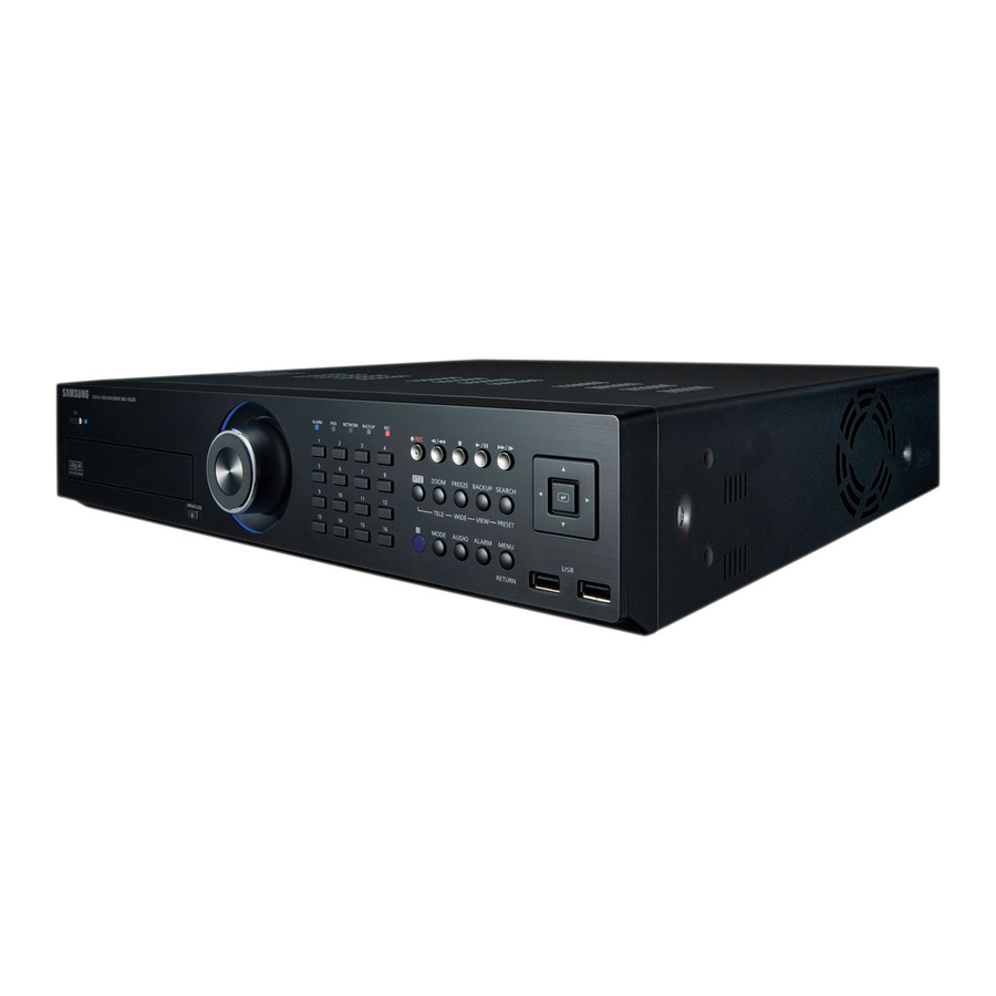
Page 8: Part Names And Functions (Front)
PART NAMES AND FUNCTIONS (FRONT) SRD-852D ALARM NETWORK BACKUP ZOOM FREEZE BACKUP SEARCH TELE WIDE VIEW PRESET MODE AUDIO ALARM MENU DIGTAL VIDEO RECORDER SRD-852D DVD RECORDER OPEN/CLOSE RETURN SRD-1652D ALARM NETWORK BACKUP ZOOM FREEZE BACKUP SEARCH TELE WIDE VIEW PRESET MODE... - Page 9 Part Names Functions ALARM : Lights on when an event occurs. HDD : Displays the normal access to HDD. Upon access to HDD, LED repeats on and off. LED Indicator NETWORK : Displays both network connection and data transfer status. BACKUP : Displays when Backup is in progress.
-
Page 10: Part Names And Functions (Rear)
PART NAMES AND FUNCTIONS (REAR) SRD-852D SRD-1652D 10_ overview... - Page 11 RS-485 Used for RS-485 communication. (TX+, TX-, RX+, RX-) - ALARM IN 1~16 (SRD-1652D) : Alarm Input port. - ALARM IN 1~8 (SRD-852D) : Alarm Input port. ALARM - ALARM RESET IN : Alarm Reset port. - ALARM OUT 1~4 : Alarm Output port.
-
Page 12: Remote Control
overview REMOTE CONTROL Available after switching to DVR mode by pressing the [DVR] button on the remote control. BACKUP SEARCH Displays the search menu. Displays the Backup Menu. OPEN/CLOSE Opens or closes the CD tray. MODE Changes the screen mode. Activates the DVR function. - Page 13 MONITOR Available after switching to Monitor mode by pressing the [MONITOR] button on the remote control. AUTO ID RESET Selects the screen status automatically. Initializes the ID value to 00. P.MODE Selects the screen mode. POWER MONITOR Turns the monitor power on/off. Activates the monitor function.
-
Page 14: Installation
Life (Unit: HOURS) [Figure 1] The followings are the recommendations when Samsung DVR is installed on a rack. Please ensure that the rack inside is not sealed. Please ensure the air is circulated through the inlet/outlet as shown in the picture. -
Page 15: Rack Installation
RACK INSTALLATION Install the Bracket-Rack as shown in the fi gure, and then fasten the screws on both sides (2 screws on each side). Fix the screws not to be loosened by vibrations. HDD ADDITION You can install additional HDDs. Make sure to unplug the power cord from the wall outlet to prevent possible electric shock, injury or product damage. - Page 16 installation If adding HDDs The following fi gures are based on Model SRD-1652D. First, loosen the screws on both sides and remove the cover. Cover Disconnect the power and HDD Signal cable from the existing HDDs, then loosen the screws (x4) in Upper Bracket the left/right and upper sides and remove the upper brackets.
- Page 17 When the installation of additional HDDs is done, insert the lower and upper brackets into the DVR and fi x them with the provided screws. When the installation of additional HDDs is done, connect the power cable and connect the HDD data cables (SATA Cable) to connectors the main board.
-
Page 18: Connecting With Other Device
connecting with other device The following fi gures are based on Model SRD-1652D. CONNECTING THE VIDEO, AUDIO, AND MONITOR AC 100-240V~IN AUDIO OUT VIDEO IN VIDEO IN SPOT AUDIO IN VIDEO OUT VIDEO OUT (composite) (VGA) CONNECTING THE USB By factory default, a USB port is provided for external connection. -
Page 19: Connecting Pos Device
button and set -
Page 20: Connecting The Rs-485 Device
• ALARM IN 1 ~ 8 (SRD-852D) : Alarm Input Port • ALARM IN 1 ~ 16 (SRD-1652D) : Alarm Input Port • ALARM RESET : On receiving an Alarm Reset signal, the system cancels the current Alarm Input and resumes sensing. -
Page 21: Connecting The Network
CONNECTING THE NETWORK Connecting to Internet through Ethernet (10/100BaseT) RJ-45 Ethernet Cable (Direct Cable) INTERNET Back Bone Hub/Switcher Hub/Switcher Windows Network Viewer Connecting to the Internet using the router INTERNET xDSL or Cable xDSL or Cable Modem Modem Router External Remote DDNS Server (Data Center) English _21... - Page 22 connecting with other device Connecting to Internet through ADSL RJ-45 Ethernet Cable (Direct Cable) INTERNET Phone(ADSL) Line ADSL MODEM Hub/Switcher Windows Network Viewer 22_ connecting with other device...
-
Page 23: Live
live GETTING STARTED Starting the system Connect the power cable of the DVR to the wall outlet. Press the Power button on the front panel. You will see the initialization screen. The initialization process will last about 1 minute. If a new HDD is installed, the initialization process may take longer. -
Page 24: Locking All Buttons
live Login To access a DVR or restricted menu, you should have logged in to the DVR. In live mode, right-click any area of the screen. Scene Mode 2011-01-01 01:10:25 You will see the context sensitive menu as in the right ZOOM Audio Off fi... -
Page 25: Live Screen Configuration
LIVE SCREEN CONFIGURATION Icons on the Live Screen You can check the status or operation of the DVR with the icons on the live screen. 2011-01-01 00:00:01 CAM 01 CAM 01 Name Description Current Date, Time Displays the current time and date. Login Information When you are logged in, the “LOG ON”... - Page 26 live Error Information • If the internal HDD is not connected, the “NO HDD”( ) message will appear; if there occurs a problem, you will see the “HDD FAIL”( ) message in the top left corner. In this case, make sure you contact the service center for assistance as this may cause a failure of recording, playback or backup.
- Page 27 Menu Description Scene Mode Refer to “Live Mode”. (Page 29) Spot Out Refer to “Spot Out”. (Page 31) ZOOM Refer to “Zoom”. (Page 32) Audio On/Off Refer to “Audio ON/OFF”. (Page 32) Freeze Refer to “Freeze”. (Page 32) Stop Alarm Stops the alarm output and the event monitoring.
-
Page 28: View The Launcher Menu
Launcher menu. If no input is entered for 10 seconds, the menu will disappear. The Launcher menu can be accessed only by using the mouse. SRD-852D do not support the 16-split screen mode. 2011-01-01 01:10:25 Alarm Freeze Menu Description Displays the current time and date. -
Page 29: Live Mode
Press the [MODE] button on the front panel or the remote control to switch the mode in the sequence of the launcher menu items. SRD-852D do not support the 16-split screen mode. CH10 CH11 CH12 CH13... -
Page 30: Channel Setting
live Manual Switching Press the left/right button on the front panel or the remote control, or click the arrow <◄/►> key to move to the next split mode. • If pressing the right [►] button in 9-split mode : 9-split (CH 1~9) mode 9-split (CH 10~16) mode Auto Sequence CH10... -
Page 31: Spot Out
Switching to Single Mode When in split mode, select and double-click a desired channel to switch to its Single mode. Press the number corresponding to a desired channel on the front panel or the remote control to switch to its Single mode. -
Page 32: Zoom
live ZOOM This is available only in Single Live mode. In Single mode, select a desired area and use the Zoom function to enlarge it twice. Selectin the right-click menu. Press the [ZOOM] button on the front panel or the remote control, or simply click < >... -
Page 33: Event Monitoring
EVENT MONITORING This will display the channel in sync with a specifi c event (Sensor/Motion/Video Loss) if it occurs. In “Monitor > Event Display”, set the event monitoring to ON/OFF and specify the event display time. (Page 50) • If multiple events occur simultaneously, the screen will switch to a split mode. - 2~4 events : 4-split mode - 5~9 events : 9-split mode - 10~16 events : 16-split mode... -
Page 34: Using The Dvr
using the DVR You can setup the system properties, devices, and options for recording, event, backup and network. SYSTEM SETUP You can setup Date/Time/Language, Permission, System Properties and Log. Date/Time/Language You can check and setup the current Date/Time and time related properties, as well as the language used for the interface on the screen. -
Page 35: Using The Calendar
- Time Server : Enter an IP or URL address of the time Date/Time/Language server. Date/Time/Language Holiday - Last Sync Time : Displays the most recent Date 2011 -01-01 YYYY-MM-DD Time Synchronization Setup synchronization time from the selected time server. - Activate as Server : Set to - Page 36 using the DVR Permission Management You can set permissions of each user over the DVR's specifi c function and settings. Setting the Administrator You can set and change Administrator’s ID and password. The administrator can use and set all menu items and functions. Using the mouse may help make setup easier.
-
Page 37: Setting The Group
Setting the Group You can create user groups and setup permissions for those user groups. You can register a user for each group in. Using the mouse may help make setup easier. Use the up/down buttons () in window to Permission Management move to , and press Group... -
Page 38: To Change The User Password
using the DVR To restrict the user permissions If the admin restricts all permissions of an added group, the users belonging to that group can access only the default minimum menus and can change the user’s own password only. Start the DVR. If all permissions are restricted, only the Login dialog should appear. -
Page 39: Setting The User
Setting the User Users can be added only if a group was created inmenu. Using the mouse may help make setup easier. Use the up/down buttons () in window to Permission Management move to , and press User Admin Group... -
Page 40: System Management
using the DVR • Manual Input of ID : Prompts you to enter the user ID manually for the login process. - Checked ( ) : Encloses the registered user IDs with the [ ] symbols. Login Use the virtual keyboard to enter the user ID. ***** Password When the permission setup is done, press. - Page 41 • Updating the Software Connect a device storing the software to be updated. System Management (It may take about 10 seconds to recognize the device.) System Information Settings Upgradeable devices include USB memory, CD/DVD and System Information Software Version V1.00h_100315180929 network device.
-
Page 42: Log Information
using the DVR Settings You can copy and import the DVR settings by using a storage media. Using the mouse may help make setup easier. Use the up/down buttons () inwindow to System Management move to , and press [ENTER] Settings System Information button. -
Page 43: Event Log
Event Log Event log shows recorded events on alarms, motion detections and video loss. It also shows the log and its timestamp. Using the mouse may help make setup easier. Use the up/down buttons () inwindow to Log Information move to , and press [ENTER] button. -
Page 44: Setting The Device
using the DVR SETTING THE DEVICE You can setup Camera, Storage Device, Remote Device, POS Device and Monitor. Camera Setting the Camera You can set Video, Audio, Channel Name and Dwell Time of a Camera. Using the mouse may help make setup easier. Press the [MENU] button on the remote control or front Logout panel. -
Page 45: Setting The Ptz
• Progressive : You can set the progressive camera to ON/OFF. If you set it tofor the progressive camera, screen fl ickering will be reduced. • Screen Setup : The video appeared on the screen may vary depending on the channel’s camera, confi... -
Page 46: Storage Device
- Replace : Requires immediate replacement. • HDD Map : Shows the internal HDD’s locations according to HDD Map assigned numbers. Refer to this for servicing or additional HDD installation. To move to the previous menu, press. 46_ using the DVR... -
Page 47
Formatting You can format a storage device. Using the mouse may help make setup easier. Use the up/down buttons () in
window to Storage Device move to , and press [ENTER] button. Format Device HDD Alarm Select . Device Select Used/Total... -
Page 48
using the DVR • Duration : Sets the alarm duration for the alarm signal and beep sound. - Check Alarm, Replace Alarm signals will output through the selected alarm out ports (1, 2, 3, and 4). - If
was selected, a beep will sound. - If ... - Page 49 • POS Device Setup : Sets the communication setups for the POS Device POS device and DVR. POS USE POS Device Setup It is independent to the Remote Device setup. Preset Port/Ethernet None No preset None POS Device Setup None No preset None...
-
Page 50: Screen Setup
using the DVR Monitor You can confi gure information to be displayed and its format for Spot Out monitor. Setting the Monitor Using the mouse may help make setup easier. Use the up/down buttons () inwindow to Monitor move to , and press [ENTER] button. -
Page 51: Setting The Spot Out
Setting the Spot Out You can set the DVR to output information / video apart from the monitor out. Using the mouse may help make setup easier. Use the up/down buttons () inwindow to Monitor move to , and press [ENTER] button. Spot Out Monitor Mode... -
Page 52: Setting The Recording
using the DVR SETTING THE RECORDING You can setup scheduled recording, event recording and other recording related settings. Recording Schedule Make your reservation on a date and time to schedule the recording on specifi ed time. Using the mouse may help make setup easier. Press the [MENU] button on the remote control or front panel. -
Page 53: Event Record Duration
Recording Color Tags Color Function Description White No Recording No schedule / event recording Orange Continuous Scheduled recording only Blue Event Event recording only Green Both(Cont&Evnt) Both scheduled / event recordings Each press of a selected cell will cycle through- - - -
Page 54: Record Option
using the DVR Setting Event Recording Properties You can set each channel’s resolution, quality and IPS for event recordings. Using the mouse may help make setup easier. Use the up/down buttons () inwindow to REC Quality & Resolution move to Page 55: Setting The Event
SETTING THE EVENT You can set recording options for sensor, motion, and video loss event. Sensor Detection You can set the sensor’s operating condition and connected camera, as well as alarm output and its duration. Using the mouse may help make setup easier. Press the [MENU] button on the remote control or front Logout Exit...Page 56: Motion Detection
using the DVR Motion Detection You can set target detection region and motion, as well as the alarm signal output. When the motion detection region is set, it detects motion within the area. Using the mouse may help make setup easier. Use the up/down buttons () in... Page 57: Video Loss Detection
Video Loss Detection You can set the alarm to be generated on a camera disconnection, which causes a video loss. Using the mouse may help make setup easier. Use the up/down buttons () inwindow to Video Loss Detection move to Page 58: Backup
(such as Windows Media Player) on a PC. - DVR : Saved data can be played back only by the DVR. - SEC : Saves data in the Samsung’s proprietary format with built-in viewer, which supports immediate playback on a PC.Page 59: Network Configuration
When the backup setup is done, press. If no available device is recognized for backup, button is not activated. The application may slow down during the backup. You can switch to the menu screen during the backup in operation, but playback of data is not available. ... Page 60: Setting The Protocol
using the DVR • IP, Gateway, Subnet Mask, and DNS Connection Mode - For: You can directly input IP address, Connection Protocol Gateway, Subnet Mask and DNS. Connection Mode ADSL Bandwidth 600kbps - For : IP address, Gateway, and Subnet Mask are set automatically. Page 61: Connecting And Setting The Network
User Name Refer to “Using Virtual Keyboard”. (Page 36) User Password ******** If selectedor , input fi elds are deactivated. If you select , the “DDNS host address” item will be displayed. Cancel When the DDNS setup is done, press . - Page 62 using the DVR When a router is used To avoid IP address confl ict with the DVR's static IP, check followings : • Setting the DVR with a static IP - Internet connection : You can connect the DVR to a router which is connected to an ADSL/Cable modem or a router in a Local Area Network (LAN) environment.
Page 63: Ddns Setting
Setin the menu of the connected DVR to the following : Ex) Protocol Type : TCP Port (TCP) : 0554, 0555, 0556, 0557, 0558 DDNS Site : Samsung DDNS • DDNS Settings of the Router Select the corresponding menu for the network transfer protocol of the router. Page 64: Mailing Service
using the DVR Mailing Service You can send an e-mail to a DVR-registered user at a specifi c time interval, or if an event occurs. If an event occurs with a channel where the camera’s video is set toor the remaining recording count is set to , only the text notifi... Page 65: Group Setting
Group Setting You can set the group to whom the e-mail is sent, and specify the permission for each group. You can add recipients for each group in themenu item. The recipient is set separately from the DVR user group. Using the mouse may help make setup easier. Page 66: Controlling A Ptz Device
using the DVR CONTROLLING A PTZ DEVICE The DVR enables you to adjust the settings of a PTZ camera as well as an ordinary one to your preference. PTZ Device The PTZ device can be activated only if a channel in connection with the PTZ camera is selected. Getting started with PTZ The PTZ camera is available, only if a channel is selected, in the following way : ...Page 67: Camera Setting
Pattern : Makes the PTZ camera remember and follow the past route. The functions of Auto Pan, Scan and Pattern are supported in the protocols of Samsung, Panasonic and Pelco, and are different in terms of the name and setting, depending on the protocols of Samsung, Panasonic and Pelco.Page 68: Search & Play
search & play SEARCH You can perform the search for recorded data by the time or by the search criteria such as an event. You can access themenu directly in Live mode. In Live mode, right-click any area of the screen. Scene Mode 2011-01-01 01:10:25 The Live menu appears. Page 69: Event Search
• Zoom In : The map enlarges in detail. Time Search It will switch in the sequence of 24 hours - 16 hours - 8 hour 2011-01-01 Go to First Go to Last - 4 hours. Overlapped Data List1 Zoom In Zoom Out •...Page 70: Pos Search
search & play POS Search You can search for data in the POS device that is connected to the DVR. You can use the mouse to select the related items. Selectin the menu. POS Search Use direction buttons (◄ ►) to set the search criteria Date/Time 2011-01-01 01:01:01 2011-01-01 03:41:18... Page 71: Playback
PLAYBACK Play You can play data stored in the HDD and backup a desired portion of the data. Using the mouse may help make setup easier. In Live mode, clickin the right-click menu or Scene Mode 2011-01-01 01:10:25 <... - Page 72 search & play Using the Playback Button Part Names Functions Play Timeline Indicates the current playback point, and can be used to move. Skip Backward Moves backward by unit time. Backward Fast Used for quick backward search while in Play. Play Backward Slow Used for backward frame-by-frame search while in PAUSE.
Page 73: Web Viewer
web viewer INTRODUCING WEB VIEWER What is Web Viewer? Web Viewer allows remote access to your DVRs. You have access to live video, archived video, PTZ control (if confi gured), etc. PRODUCT FEATURES • Remote access from a standard browser •...Page 74: Connecting Web Viewer
web viewer CONNECTING WEB VIEWER Open your web browser and type the IP address or URL of DVR into the URL address box. The basic URL of the DVR is as following in case of MAC address : 00-00-F0-ab-cd-ef : nabcdef.websamsung.net ...Page 75: Using Live Viewer
USING LIVE VIEWER The Live Viewer screen consists of following : This displays the IP address and the model name of the connected DVR. These menus consist of, , , . These buttons are used for the screen split and full screen mode. Shows the IP address and model name of the connected DVR. - Page 76 web viewer OSD INFORMATION DISPLAY The channel number, video size, and IP address of the connected DVR are displayed. The current date and time will be displayed according to the selected time information display setting
or . Alarm icon appears when alarm is issued. - Page 77 CONNECTED DVR This displays the IP address and the status of the connecting DVR. Connection failure message No Response : Appears when the DVR does not respond. Access Denied : Appears when the maximum number of users is exceeded. ...
- Page 78 CAPTURE : Saves the current screen into a BMP or JPEG fi le. The default saving path is “C:\Program Files\Samsung\Dvr Web Viewer\SnapShot\Live”. To change the saving path, click
button and then select the path you want. Page 79: Using Ptz Camera
To record it, it is required at least 1GB of available space. The default saving path is “C:\Program Files\Samsung\Dvr Web Viewer\VideoClip\Live”. To change the saving path, clickbutton and then select the path you want. - Page 80 Upward dragging will zoom out, while downward dragging will zoom in. Tilt of Power PTZ operates properly within 45°. Power and Pan Tilt functions are only available for camera supporting the functions. Ex : Samsung SCC-C6475 80_ web viewer...
Page 81: Using Search Viewer
USING SEARCH VIEWER The Search Viewer screen consists of following : This displays the IP address and the model name of the connected DVR. These menus consist of, , , . These buttons are used for the screen split and full screen mode. Shows the IP address and model name of the connected DVR. - Page 82 web viewer SPLIT-SCREEN You can change the split mode by clicking each number icon. SINGLE MODE QUAD MODE • Click < > button. The screen displays the selected camera connected to the DVR in “SINGLE MODE”. • Click < > button. The screen displays the selected camera connected to the DVR in “QUAD MODE”.
- Page 83
button and then select the path you want. For Windows Vista or 7, the saving path is “C:\users\(user ID)\AppData\LocalLow\Samsung\DVR Web Viewer\VideoClip\” and it cannot be modifi ed. The fi le is automatically named as following : “IP address_Port number_YYYYMMDD_camera number_index”... Page 84: Searching The Recorded Video In The Calendar
web viewer SEARCHING THE RECORDED VIDEO IN THE CALENDAR If the video data has been recorded on a date, the date is distinguished in green. If you click the date, the recorded video information is displayed in the time line. When you click, it will be synchronized with the system time (date) of the current PC. Page 85: Controlling Playback
CONTROLLING PLAYBACK Fast Backward : Reverse-plays faster(2x). Reverse Play : Performs Reverse Play. Play : Performs playback. Fast Forward : Plays faster(2x). Go to First : Moves the beginning time of recorded video in the time line. Step Backward : Performs one step reverseplay by one frame. Pause : Stops the playback temporarily.- Page 86 web viewer • Time Synchronization Setup Set the time synchronization. • Display Date Format : Set the date type. Time : Select a time format to display on the screen. • DST (Daylight Saving Time) DST is displayed an hour ahead of the standard time of the time zone.
- Page 87 • Group Users are classifi ed into groups and the permission can be set according to the group. First of all, add a group. • User You can add, change or remove a user or users. • Setup You can set the user permission. System Management For more information, refer to
... - Page 88 web viewer Device You can check a list of devices that are connected to the DVR and confi gure the necessary settings. Click
in the menu screen. For more information, refer to “Setting the Device”. (Page 44) Camera • Camera You can confi... Page 89: Remote Device
• HDD Alarm You can set the alarm output channel and the alarm duration for an error. Remote Device You can see a list of remote devices including PTZ cameras and system keyboards that are connected to the RS-485 port of the DVR and confi...Page 90: Recording Schedule
web viewer • Spot Out If an event occurs such as sensor, motion or alarm from the Spot Out port in connection with a monitor, you can select a output screen mode. • Mode You can switch between live mode and play mode. Record For more information, refer to. Page 91: Sensor Detection
Event Record Duration You can set the start and end times of recording that will be activated if an event occurs. REC Quality & Resolution • Standard/Event You can set the resolution, frame rate and recording quality for each channel. Record Option You can set the Disk End Mode.- Page 92 web viewer Motion Detection You can set the motion detection mode and the sensitivity as well as the alarm output type and the duration. • Motion Region Set the target motion detection area Video Loss Detection You can set the alarm output time if a video loss occurs. Alarm Schedule You can schedule the alarm output according to the day of the week and the time.
Page 93: Live Transfer
Network For more information, refer to. (Page 59) Connection A remote user can access the DVR via the network to check the current mode and the IP address. • Connection You can set the network connection route. •... - Page 94 web viewer Mailing Service You can specify the SMTP server that sends a mail if an event occurs and set the recipient group and users. • SMTP You can set the server that sends mails and specify if you use the authentication process.
Page 95: About
ABOUT Click. Displays the model name of connected DVR and the version of Web Viewer. MOBILE VIEWER What is Mobile Viewer? Mobile Viewer is management software that enables you to connect to DVR (Digital Video Recorder) remotely and control the video playback and PTZ operations (if confi... Page 96: Backup Viewer
backup viewer SEC BACKUP VIEWER You can play a fi le that is backed up in the format of SEC. Backup in the format of SEC will involve in generating two fi les: one for the backup data and one for the viewer. If you run the backup fi...- Page 97 Name Description A toggle button. Each time you press this button, the audio output will toggle between activated and deactivated. Audio You can adjust the volume level from 0 to 100. Saves the current screen as an image fi le. Supported fi le formats include BMP and JPEG.
Page 98: Appendix
PRODUCT SPECIFICATION Details Item SRD-1652D SRD-852D 8 composite video 0.5–1 Vpp Inputs 16 composite video 0.5–1 Vpp Video Resolution 704x480 NTSC, 704x576 PAL 240ips NTSC, 200ips PAL Frame rate 480ips NTSC, 400ips PAL Live Resolution 704x480 NTSC, 704x576 PAL...- Page 99 Details Item SRD-1652D SRD-852D Up to (8)Mbps, Unlimited(8M)/2/1.5/1Mbps/800/600/500/400/300/200/100/ Transmission speed 50kbps Bandwidth control Selectable Stream H.264(Max CIF 120ips) Network Remote users Search(3) / Live Unicast(10) / Live Multicast(20) Maximum Protocol support TCP/IP, DHCP, PPPoE, SMTP, NTP, HTTP, DDNS, RTP, RTSP...
- Page 100 USB 2.0, 2 ports(Front) Connections e-SATA Application Supoort Mouse, Remote Controller Samsung-E/ Samsung-T/ Pelco-D/ Pelco-P / Panasonic/ Phillips/ AD/ DIAMOND/ PTZ Protocol support ERNA/ GE/ VCL TP/VICON General Input Voltage /Current 100 to 240 VAC ±10%; 50/60 Hz, Autoranging Electrical Power consumption Max.
Page 101: Product Overview
PRODUCT OVERVIEW • SRD-1652D unit : mm (inches) 440,0 (17.32") English _101...Page 102: Default Setting
appendix DEFAULT SETTING This returns the factory default settings. The settings are made as follows; • Use System/Load Factory Default in MENU The default settings are based on SRD-1652D Category Details Factory Default Date YYYY-MM-DD Time Format 24 hours Time Zone Date/Time/Language Date/Time/Language...- Page 103 Category Details Factory Default POS Device Display Switch to Split Screen 5 sec Monitor 800x600 Device Sharpness Level1(Low) Monitor Display Position Setup Spot Out Spot Out Live Mode Mode Play Mode Recording Schedule Channel 1 Event PRE Event Event Record Duration POST Event 1 min...
- Page 104 appendix Category Details Factory Default Connection Mode Static IP Bandwidth 2Mbps 192.168.1.200 Connection Gateway 192.168.1.1 Connection Mode Subnet Mask 255.255.255.0 168.126.63.1 Protocol Type Protocol Port (TCP) 554~558 Webviewer Port DDNS DDNS Site Network Resolution CIF(S) Live Transfer Quality Server Port SMTP Use Authentication Secure Transfer...
Page 105: Troubleshooting
TROUBLESHOOTING Symptom Countermeasures The system does not turn on and the indicator on the Check if the power supply system is properly connected. front panel does not work at all. Check the system for the input voltage from the power source. If the problem persists even after you have taken the above actions, check the power supplier and replace it with a new one if neccessary.- Page 106 appendix Symptom Countermeasures I've found that the DVR does not recognize as many It takes time for the DVR to recognize multiple external HDDs. Try again disks as installed when I have connected multiple in a moment and if the problem (of failure to recognize as many HDDs external HDDs to the DVR.
- Page 107 Symptom Countermeasures Recording does not work. If your player does not display a Live image at all, that indicates recording does not work so fi rst check if you see an image on the screen. Recording does not work if the recording settings are not properly confi...
Page 108: Open Source License Report On The Product
Corresponding Source code from us for a period of three years after our last shipment of this product by sending email to [email protected] If you want to obtain the complete Corresponding Source code in the physical medium such as CD-ROM, the cost of physically performing source distribution might be charged.- Page 109 of the Program a copy of this License along with the Accompany it with a written offer, valid for at least Program. three years, to give any third party, for a charge no more than your cost of physically performing You may charge a fee for the physical act of transferring source distribution, a complete machine-readable a copy, and you may at your option offer warranty...
- Page 110 7. If, as a consequence of a court judgment or 10. If you wish to incorporate parts of the Program into allegation of patent infringement or for any other reason other free programs whose distribution conditions are (not limited to patent issues), conditions are imposed on different, write to the author to ask for permission.
Page 111: Gnu General Public License
How to Apply These Terms to Your with the library. If this is what you want to do, use the GNU Lesser General Public License instead of this New Programs License. GNU GENERAL PUBLIC LICENSE If you develop a new program, and you want it to be of the greatest possible use to the public, the best way to achieve this is to make it free software which everyone Version 3, 29 June 2007...Page 112: Terms And Conditions
Some devices are designed to deny users access to To “convey” a work means any kind of propagation that install or run modified versions of the software inside enables other parties to make or receive copies. Mere them, although the manufacturer can do so. This is interaction with a user through a computer network, fundamentally incompatible with the aim of protecting with no transfer of a copy, is not conveying.- Page 113 The Corresponding Source for a work in source code You may charge any price or no price for each copy form is that same work. that you convey, and you may offer support or warranty protection for a fee. 2. Basic Permissions. 5.
- Page 114 offer spare parts or customer support for that “Installation Information” for a User Product means any product model, to give anyone who possesses methods, procedures, authorization keys, or other the object code either (1) a copy of the information required to install and execute modified Corresponding Source for all the software in the versions of a covered work in that User Product from a product that is covered by this License, on a...
- Page 115 Notwithstanding any other provision of this License, for However, if you cease all violation of this License, then material you add to a covered work, you may (if your license from a particular copyright holder is authorized by the copyright holders of that material) reinstated (a) provisionally, unless and until the copyright supplement the terms of this License with terms: holder explicitly and finally terminates your license, and...
- Page 116 litigation (including a cross-claim or counterclaim in a A patent license is “discriminatory” if it does not include lawsuit) alleging that any patent claim is infringed by within the scope of its coverage, prohibits the exercise making, using, selling, offering for sale, or importing the of, or is conditioned on the non-exercise of one or more Program or any portion of it.
- Page 117 and conditions either of that numbered version or of any END OF TERMS AND CONDITIONS later version published by the Free Software GNU LESSER GENERAL PUBLIC Foundation. If the Program does not specify a version LICENSE number of the GNU General Public License, you may choose any version ever published by the Free Software Foundation.
- Page 118 To protect each distributor, we want to make it very The precise terms and conditions for copying, clear that there is no warranty for the free library. Also, if distribution and modification follow. Pay close attention the library is modified by someone else and passed on, to the difference between a “work based on the library”...
- Page 119 2. You may modify your copy or copies of the Library or Once this change is made in a given copy, it is any portion of it, thus forming a work based on the irreversible for that copy, so the ordinary GNU General Library, and copy and distribute such modifications or Public License applies to all subsequent copies and work under the terms of Section 1 above, provided that...
- Page 120 the work for the customer’s own use and reverse 7. You may place library facilities that are a work based engineering for debugging such modifications. on the Library side-by-side in a single library together with other library facilities not covered by this License, You must give prominent notice with each copy of the and distribute such a combined library, provided that work that the Library is used in it and that the Library...
- Page 121 If any portion of this section is held invalid or unenforceable EXPRESSED OR IMPLIED, INCLUDING, BUT NOT under any particular circumstance, the balance of the LIMITED TO, THE IMPLIED WARRANTIES OF section is intended to apply, and the section as a whole is MERCHANTABILITY AND FITNESS FOR A intended to apply in other circumstances.
Page 122: Openssl License
write to the Free Software Foundation, Inc., 51 Franklin TORT (INCLUDING NEGLIGENCE OR OTHERWISE) Street, Fifth Floor, Boston, MA 02110-1301 USA Also ARISING IN ANY WAY OUT OF THE USE OF THIS add information on how to contact you by electronic SOFTWARE, EVEN IF ADVISED OF THE POSSIBILITY and paper mail.- Page 123 PROFITS; OR BUSINESS INTERRUPTION) HOWEVER CAUSED AND ON ANY THEORY OF LIABILITY, WHETHER IN CONTRACT, STRICT LIABILITY, OR TORT (INCLUDING NEGLIGENCE OR OTHERWISE) ARISING IN ANY WAY OUT OF THE USE OF THIS SOFTWARE, EVEN IF ADVISED OF THE POSSIBILITY OF SUCH DAMAGE.The licence and distribution terms for any publically available version or derivative of this code cannot be changed.
- Page 124 Correct Disposal of This Product (Waste Electrical & Electronic Equipment) (Applicable in the European Union and other European countries with separate collection systems) This marking on the product, accessories or literature indicates that the product and its electronic accessories (e.g. charger, headset, USB cable) should not be disposed of with other household waste at the end of their working life.
Page 125: User Manual
Samsung Techwin. Disclaimer Samsung Techwin makes the best to verify the integrity and correctness of the contents in this document, but no formal guarantee shall be provided. Use of this document and the subsequent results shall be entirely on the user’s own responsibility. Samsung Techwin reserves the right to change the contents of this document without prior notice.- Page 126 SAMSUNG TECHWIN AMERICA Inc. SAMSUNG TECHWIN EUROPE LTD. 100 Challenger Rd. Suite 700 Ridgefi eld Park, NJ 07660 Samsung House, 1000 Hillswood Drive, Hillswood Business Toll Free : +1-877-213-1222 Direct : +1-201-325-6920 Park Chertsey, Surrey, UNITED KINGDOM KT16 OPS Fax : +1-201-373-0124 TEL : +44-1932-45-5300 FAX : +44-1932-45-5325 www.samsungcctvusa.com...