Table of Contents
Quick Links
Table of Contents

Related Manuals for Asus M2N68-AM PLUS ION SI


Summary of Contents for Asus M2N68-AM PLUS ION SI
- Page 1 M2N68-AM...
- Page 2 Product warranty or service will not be extended if: (1) the product is repaired, modified or altered, unless such repair, modification of alteration is authorized in writing by ASUS; or (2) the serial number of the product is defaced or missing.
-
Page 3: Table Of Contents
Welcome! ..................1-2 Package contents ................. 1-2 Special features ................1-2 1.3.1 Product highlights ............1-2 1.3.2 Innovative ASUS features ..........1-4 Before you proceed ..............1-6 Motherboard overview ..............1-7 1.5.1 Motherboard layout ............1-7 1.5.2 Placement direction ............1-8 1.5.3... - Page 4 Chapter 2: BIOS setup Managing and updating your BIOS ..........2-2 2.1.1 Creating a bootable floppy disk ........2-2 2.1.2 ASUS EZ Flash 2 utility ........... 2-4 2.1.3 AFUDOS utility ..............2-5 2.1.4 ASUS CrashFree BIOS 3 utility ........2-7 2.1.5...
- Page 5 Boot Device Priority ............-36 2.6.2 Boot Settings Configuration ..........-37 2.6.3 Security ................-38 Tools menu ................... -40 ASUS EZ Flash 2 ............-40 2.7.1 2.7.2 AI NET 2................-41 Exit menu ..................-42 Software support Installing an operating system ............. -2 Support DVD information ..............
-
Page 6: Notices
Notices Federal Communications Commission Statement This device complies with Part 15 of the FCC Rules. Operation is subject to the following two conditions: • This device may not cause harmful interference, and • This device must accept any interference received including interference that may cause undesired operation. -
Page 7: Safety Information
Safety information Electrical safety • To prevent electrical shock hazard, disconnect the power cable from the electrical outlet before relocating the system. • When adding or removing devices to or from the system, ensure that the power cables for the devices are unplugged before the signal cables are connected. If possible, disconnect all power cables from the existing system before you add a device. -
Page 8: About This Guide
Refer to the following sources for additional information and for product and software updates. ASUS websites The ASUS website provides updated information on ASUS hardware and software products. Refer to the ASUS contact information. Optional documentation Your product package may include optional documentation, such as warranty flyers, that may have been added by your dealer. -
Page 9: Conventions Used In This Guide
Conventions used in this guide To ensure that you perform certain tasks properly, take note of the following symbols used throughout this manual. DANGER/WARNING: Information to prevent injury to yourself when trying to complete a task. CAUTION: Information to prevent damage to the components when trying to complete a task. -
Page 10: M2N68-Am Specifications Summary
M2N68-AM specifications summary Support AMD socket AM2/AM2+ for AMD Phenom™ FX / Phenom™ / Athlon™ / Sempron™ processors AMD64 architecture enables simultaneous 32-bit and 64-bit computing Supports AMD Cool ‘n’ Quiet™ Technology Chipset MCP68S/MCP68PVNT System bus 2000 / 1600 MT/s Memory Dual-channel memory architecture 2 x 240-pin DIMM sockets support up to 4 GB of unbufferred ECC and... - Page 11 SFS (Stepless Frequency Selection) up to 300MHz at Features 1MHz increment Adjustable CPU Voltage at 0.033V increment Intelligent overclocking tool: AI Overclocking (Intelligent CPU Frequency Tuner) ASUS C.P.R. (CPU Parameter Recall) ASUS Special Features ASUS Q-Fan ASUS CrashFree BIOS 3 ASUS EZ Flash 2 ASUS MyLogo 2™...
-
Page 13: Chapter 1: Product Introduction
This chapter describes the motherboard features and the new technologies it supports. Product introduction... -
Page 14: Welcome
® The motherboard delivers a host of new features and latest technologies, making it another standout in the long line of ASUS quality motherboards! Before you start installing the motherboard, and hardware devices on it, check the items in your package with the list below. - Page 15 DDR2 1066 is for AM2+ only. Serial ATA 3Gb/s technology The motherboard supports SATA hard drives based on the new SATA 3Gb/s storage specification. It allows RAID 0, RAID 1, RAID 5, RAID 10, and JBOD configurations for four SATA connectors. ASUS M2N68-AM...
-
Page 16: Innovative Asus Features
See page 2-35 for details. ASUS CrashFree BIOS 3 The ASUS CrashFree BIOS 3 allows users to restore corrupted BIOS data from a USB flash disk containing the BIOS file. See page 2-7 for details. -
Page 17: Asus Mylogo 2
The motherboard and its packaging comply with the European Union’s Restriction on the use of Hazardous Substances (RoHS). This is in line with the ASUS vision of creating environment-friendly and recyclable products and packaging to safeguard consumers’ health while minimizing the impact on the environment. -
Page 18: Before You Proceed
Before you proceed Take note of the following precautions before you install motherboard components or change any motherboard settings. • Unplug the power cord from the wall socket before touching any component. • Use a grounded wrist strap or touch a safely grounded object or a metal object, such as the power supply case, before handling components to avoid damaging them due to static electricity •... -
Page 19: Motherboard Overview
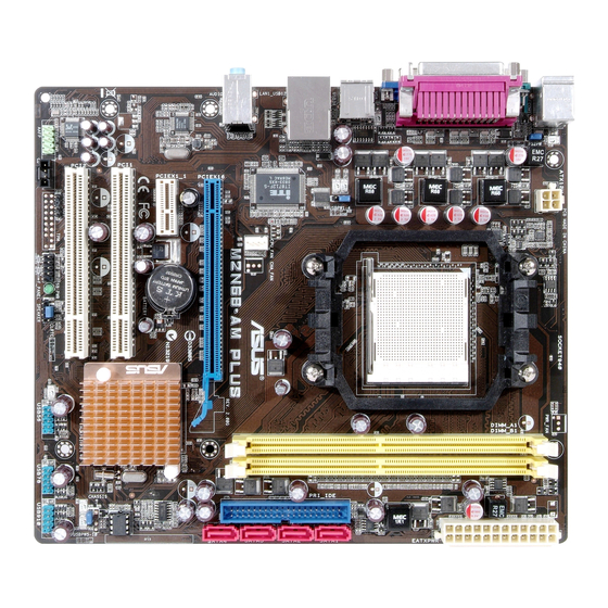
Motherboard layout 22.2cm(8.75in) KBMS ATX12V USB34 LAN1_USB12 Super M2N68-AM AUDIO CPU_FAN PCIEX16 8211CL Lithium Cell PCIEX1_1 CMOS Power BIOS Nvidia ® SPEAKER MCP68 CLRTC Family PCI1 SATA1 SATA2 PCI2 SATA3 SATA4 USB56 USB78 USB910 SPDIF_OUT F_PANEL FLOPPY AAFP SB_PWR ASUS M2N68-AM... -
Page 20: Placement Direction
1.5.2 Placement direction When installing the motherboard, ensure that you place it into the chassis in the correct orientation. The edge with external ports goes to the rear part of the chassis as indicated in the image below. 1.5.3 Screw holes Place six (6) screws into the holes indicated by circles to secure the motherboard to the chassis. -
Page 21: Central Processing Unit (Cpu)
M2N68-AM CPU socket AM2+ Unlock the socket by pressing the lever sideways, then lift it up to a 90°-100° angle. Socket lever Ensure that the socket lever is lifted up to 90°-100° angle, otherwise the CPU does not fit in completely. ASUS M2N68-AM... - Page 22 Position the CPU above the socket such that the CPU corner with the gold triangle matches the socket corner with a small triangle. Carefully insert the CPU into the socket until it fits in place. Small triangle Gold triangle The CPU fits only in one correct orientation. DO NOT force the CPU into the socket to prevent bending the pins and damaging the CPU! When the CPU is in place, push down the socket lever to secure the...
-
Page 23: Installing The Heatsink And Fan
Retention bracket lock Your boxed CPU heatsink and fan assembly should come with installation instructions for the CPU, heatsink, and the retention mechanism. If the instructions in this section do not match the CPU documentation, follow the latter. ASUS M2N68-AM 1-11... - Page 24 Attach one end of the retention bracket to the retention module base. Align the other end of the retention bracket (near the retention bracket lock) to the retention module base. A clicking sound denotes that the retention bracket is in place. Ensure that the fan and heatsink assembly perfectly fits the retention mechanism module...
-
Page 25: System Memory
240-pin footprint compared to the 184-pin DDR DIMM. DDR2 DIMMs are notched differently to prevent installation on a DDR DIMM socket. The figure illustrates the location of the DDR2 DIMM sockets: M2N68-AM M2N68-AM 240-pin DDR2 DIMM sockets Channel Sockets Channel A DIMM_A1 Channel B DIMM_B1 ASUS M2N68-AM 1-13... -
Page 26: Memory Configurations
1.7.2 Memory configurations You may install 256 MB, 512 MB, 1 GB, and 2 GB unbuffered non-ECC DDR2 DIMMs into the DIMM sockets. Recommended memory configurations Sockets Mode DIMM_A1 DIMM_B1 – Populated Single-Channel Populated – Dual-channel Populated Populated • When using only one memory module, start installing the DDR2 DIMM from slot DIMM_A1 or DIMM_B1 for better overclocking capability. - Page 27 HYMP564U64AP8-S6 AA Hynix HY5PS12821AFP-S6 • • 512MB HYMP564U64BP8-S5 AB Hynix HY5PS12821BFP-S5 • • 512MB HYMP564U64CP8-S5 AB Hynix HY5PS12821CFP-S5 • • HYMP512U64AP8-S6 AA Hynix HY5PS12821AFP-S6 • • HYMP512U64BP8-S5 AB Hynix HY5PS12821BFP-S5 • • (continued on the next page) ASUS M2N68-AM 1-15...
- Page 28 DDR2-800 MHz capability DIMM support Size Vendor Model Brand Component HYMP512U64CP8-S5 AB Hynix HY5PS12821CFPS5 • • 512MB ADATA M20AD6G3H3160I1E58 ADATA AD29608A8A-25EG80720 • • 512MB VDATA M2GVD6G3H3160I1E53 VDATA VD29608A8A-25EG30648 • • VDATA M2GVD6G3I4170I1E53 VDATA VD29608A8A-25EG30647 • • 512MB AL6E8E63B-8E1K A3R12E3HEF641B9A05 • •...
- Page 29 HY5PS121621CFP-C4 • • HYMP512U64CP8-C4 AB Hynix HY5PS12821CFP-C4 • • 512MB Micron MT 16HTF6464AG-53EB2 Micron D9BOM • • 512MB Micron MT 16HTF6464AG-53EB2 Micron Z9BQT • • Micron MT 16HTF12864AY-53EA1 Micron D9CRZ • • (continued on the next page) ASUS M2N68-AM 1-17...
- Page 30 A*: Supports one module inserted into any slot as Single-channel memory configuration. • B*: Supports one pair of modules inserted into either the yellow slots as one pair of Dual-channel memory configuration. Visit the ASUS website for the latest QVL. 1-18 Chapter 1: Product introduction...
-
Page 31: Installing A Dimm
DIMM. DDR2 DIMM notch Support the DIMM lightly with your fingers when pressing the retaining clips. The DIMM might get damaged when it flips out with extra force. Remove the DIMM from the socket. ASUS M2N68-AM 1-19... -
Page 32: Expansion Slots
Expansion slots In the future, you may need to install expansion cards. The following sub-sections describe the slots and the expansion cards that they support. Ensure to unplug the power cord before adding or removing expansion cards. Failure to do so may cause you physical injury and damage motherboard components. -
Page 33: Interrupt Assignments
When using PCI cards on shared slots, ensure that the drivers support “Share IRQ” or that the cards do not need IRQ assignments. Otherwise, conflicts will arise between the two PCI groups, making the system unstable and the card inoperable. ASUS M2N68-AM 1-21... -
Page 34: Pci Slots
1.8.4 PCI slots The PCI slots support cards such as a LAN card, SCSI card, USB card, and other cards that comply with PCI specifications. The figure shows a LAN card installed on a PCI slot. 1.8.5 PCI Express x1 slot This motherboard supports PCI Express x1 network cards, SCSI cards and other cards that comply with the PCI Express... -
Page 35: Jumper
You do not need to clear the RTC when the system hangs due to overclocking. For system failure due to overclocking, use the C.P.R. (CPU Parameter Recall) feature. Shut down and reboot the system so the BIOS can automatically reset parameter settings to default values. ASUS M2N68-AM 1-23... -
Page 36: 1.10 Connectors
1.10 Connectors 1.10.1 Rear panel connectors PS/2 mouse port (green). This port is for a PS/2 mouse. Parallel port. This 25-pin port connects a parallel printer, a scanner, or other devices. LAN (RJ-45) port. Supported by RTL8211CL Gigabit LAN controller, this port allows Gigabit connection to a Local Area Network (LAN) through a network hub. -
Page 37: Internal Connectors
FDD cable with a covered Pin 5. • The Floppy Disk Drive cable is purchased separately. FLOPPY M2N68-AM PIN1 NOTE:Orient the red markings on the floppy ribbon cable to PIN 1. M2N68-AM Floppy disk drive connector ASUS M2N68-AM 1-25... - Page 38 IDE connectors (40-1 pin PRI_IDE) The onboard IDE connector is for an Ultra DMA 133/100/66 signal cable. There are three connectors on each Ultra DMA 133/100/66 signal cable: blue, black, and gray. Connect the blue connector to the motherboard’s IDE connector, then select one of the following modes to configure your device(s).
-
Page 39: Serial Ata Hard Disk Drive Connection
If you intend to create a Serial ATA RAID set using these connectors, set the SATA Mode select item in the BIOS to [RAID Mode]. See the page 2-16 for details. Serial ATA hard disk drive connection Connector Color Setting SATA1/2 Master Boot disk SATA3/4 Slave Data disk ASUS M2N68-AM 1-27... - Page 40 CPU Fan connector (4-pin CPU_FAN) The fan connector supports cooling fans of 350mA~740mA (8.88W max.) or a total of 1A~2.22A (26.64W max.) at +12V. Connect the fan cable to the fan connector on the motherboard, ensuring that the black wire of the cable matches the ground pin of the connector.
- Page 41 The USB 2.0 module is purchased separately. Optical drive audio in connector (4-pin CD) These connectors allow you to receive stereo audio input from sound sources such as a CD-ROM, TV tuner, or MPEG card. M2N68-AM M2N68-AM Internal audio connector ASUS M2N68-AM 1-29...
- Page 42 Front panel audio connector (10-1 pin AAFP) This connector is for a chassis-mounted front panel audio I/O module that supports either High Definition Audio or AC`97 audio standard. Connect one end of the front panel audio I/O module cable to this connector. AAFP PIN 1 PIN 1...
-
Page 43: Atx Power Connectors
• If you are uncertain about the minimum power supply requirement for your system, refer to the Recommended Power Supply Wattage Calculator at http://support.asus.com/PowerSupplyCalculator/PSCalculator. aspx?SLanguage=en-us for details. • You must install a PSU with a higher power rating if you intend to install additional devices. -
Page 44: System Panel Connector
10. System panel connector (20-8 pin PANEL) This connector supports several chassis-mounted functions. PWR LED PWR BTN F_PANEL PIN 1 M2N68-AM HD_LED RESET M2N68-AM System panel connector System power LED (2-pin PLED) • This 2-pin connector is for the system power LED. Connect the chassis power LED cable to this connector. -
Page 45: Chapter 2: Bios Setup
This chapter tells how to change the system settings through the BIOS Setup menus. Detailed descriptions of the BIOS parameters are also provided. BIOS setup... -
Page 46: Managing And Updating Your Bios
The following utilities allow you to manage and update the motherboard Basic Input/Output System (BIOS) setup. ASUS EZ Flash 2: Updates the BIOS using a floppy disk, USB Flash, or the motherboard support DVD during POST. ASUS AFUDOS: Updates the BIOS in DOS mode using a bootable floppy disk. - Page 47 Right-click Floppy Disk Drive then click Format to display the Format 3 1/2 Floppy dialog box . d. Select the Create an MS-DOS startup disk check box. e. Click Start. Copy the original or the latest motherboard BIOS file to the bootable floppy disk. ASUS M2N68-AM...
-
Page 48: Asus Ez Flash 2 Utility
2.1.2 ASUS EZ Flash 2 utility The ASUS EZ Flash 2 feature allows you to update the BIOS without having to go through the long process of booting from a floppy disk and using a DOS-based utility. The EZ Flash 2 utility is built-in the BIOS chip so it is accessible by pressing... -
Page 49: Afudos Utility
Extension name Press. The utility copies the current BIOS file to the floppy disk. A:\>afudos /oOLDBIOS1.rom AMI Firmware Update Utility - Version 1.19(ASUS V2.07(03.11.24BB)) Copyright (C) 2002 American Megatrends, Inc. All rights reserved. Reading flash ..done Write to file..ok A:\>... -
Page 50: Updating The Bios File
Updating the BIOS file To update the BIOS file using the AFUDOS utility: Visit the ASUS website (www.asus.com) and download the latest BIOS file for the motherboard. Save the BIOS file to a bootable floppy disk. Write the BIOS filename on a piece of paper. You need to type the exact BIOS filename at the DOS prompt. -
Page 51: Asus Crashfree Bios 3 Utility
2.1.4 ASUS CrashFree BIOS 3 utility The ASUS CrashFree BIOS 3 is an auto recovery tool that allows you to restore the BIOS file when it fails or gets corrupted during the updating process. You can update a corrupted BIOS file using the motherboard support DVD , the floppy disk or the USB flash disk that contains the updated BIOS file. -
Page 52: Recovering The Bios From The Support Dvd
Restart the system after the utility completes the updating process. • Only the USB flash disk with FAT 32/16 format and single partition can support ASUS CrashFree BIOS 3. The device size should be smaller than 8GB. • DO NOT shut down or reset the system while updating the BIOS! Doing so... -
Page 53: Asus Update Utility
2.1.5 ASUS Update utility The ASUS Update is a utility that allows you to manage, save, and update the motherboard BIOS in Windows environment. The ASUS Update utility allows you ® • Save the current BIOS file • Download the latest BIOS file from the Internet •... - Page 54 To update the BIOS through the Internet: desktop by clicking Start Launch the ASUS Update utility from the Windows ® > Programs > ASUS > ASUSUpdate > ASUSUpdate. The ASUS Update main window appears. Select Update BIOS from Select the ASUS FTP site nearest...
- Page 55 To update the BIOS through a BIOS file: Launch the ASUS Update utility from the Windows desktop by clicking Start ® > Programs > ASUS > ASUSUpdate > ASUSUpdate. The ASUS Update main window appears. Select Update BIOS from a file option from the drop-down menu, then click Next.
-
Page 56: Bios Setup Program
The BIOS setup screens shown in this section are for reference purposes only, and may not exactly match what you see on your screen. • Visit the ASUS website (www.asus.com) to download the latest BIOS file for this motherboard. 2-12... -
Page 57: Bios Menu Screen
• The BIOS setup screens shown in this chapter are for reference purposes only, and may not exactly match what you see on your screen. • Visit the ASUS website (www.asus.com) to download the latest BIOS information. ASUS M2N68-AM 2-13... -
Page 58: Navigation Keys
2.2.3 Navigation keys At the bottom right corner of a menu screen are the navigation keys for that particular menu. Use the navigation keys to select items in the menu and change the settings. Some of the navigation keys differ from one screen to another. 2.2.4 Menu items The highlighted item on the menu bar displays the specific items for that menu. -
Page 59: Main Menu
Allows you to set the system date. 2.3.3 Legacy Diskette A [1.44M, 3.5 in.] Sets the type of floppy drive installed. Configuration options: [Disabled] [720K , 3.5 in.] [1.44M, 3.5 in.] [360K, 5.25 pin] [1.2M 5.25 pin] [2.88M, 3.5 pin] ASUS M2N68-AM 2-15... -
Page 60: Ide Configuration
2.3.4 IDE Configuration The items in this menu allow you to set or change the configurations for the IDE devices installed in the system. Select an item then pressif you wish to configure the item. Disabled: disables IDE Configuration the integrated IDE Controller. -
Page 61: Primary Ide Master/Slave
LBA/Large Mode [Auto] Enables or disables the LBA mode. Setting to Auto enables the LBA mode if the device supports this mode, and if the device was not previously formatted with LBA mode disabled. Configuration options: [Disabled] [Auto] ASUS M2N68-AM 2-17... - Page 62 Block (Multi-Sector Transfer) M [Auto] Enables or disables data multi-sectors transfers. When set to Auto, the data transfer from and to the device occurs multiple sectors at a time if the device supports multi-sector transfer feature. When set to [Disabled], the data transfer from and to the device occurs one sector at a time.
-
Page 63: Sata1, Sata2, Sata3, And Sata4
When set to [Disabled], the data transfer from and to the device occurs one sector at a time. Configuration options: [Disabled] [Auto] PIO Mode [Auto] Selects the PIO mode. Configuration options: [Auto] [0] [1] [2] [3] [4] ASUS M2N68-AM 2-19... -
Page 64: System Information
DMA Mode [Auto] Selects the DMA mode. Configuration options: [Auto] [SWDMA0] [SWDMA1] [SWDMA2] [MWDMA0] [MWDMA1] [MWDMA2] [UDMA0] [UDMA1] [UDMA2] [UDMA3] [UDMA4] [UDMA5] [UDMA6] SMART Monitoring [Auto] Enables or disables the S.M.A.R.T. (Self Monitoring and Reporting Technology) capability of your hard drive. This features allows your system to report read/write errors of the hard drive and to issue warnings when a third party hardware monitor utility is installed. -
Page 65: Advanced Menu
Memory Over voltage [Auto] Chipset Voltage Chipset Voltage [Auto] v02.61 (C)Copyright 1985-2008, American Megatrends, Inc. AI Overclocking [Auto] Allows selection of CPU overclocking options to achieve desired CPU internal frequency. Select either one of the preset overclocking configuration options: ASUS M2N68-AM 2-21... - Page 66 [Auto] - allows you to set overclocking parameters automatically. [MANUAL] - allows you to individually set overclocking parameters. [Standard] - loads the standard settings for the system. [Overclock Profile] - loads overclocking profiles with optimal parameters for stability when overclocking. The following item appears only when the AI Overclocking item is set to [MANUAL].
- Page 67 Allows you to set the memory over voltage. The value ranges from 1.85000V to 2.24375V with a 0.00625V interval. Configuration options: [Auto] [1.85000V] [2.24375V] Chipset Over Voltage [Auto] Allows you to set the chipset over voltage. Configuration options: [Auto] [+50mv] [+100mv] [+150mv] ASUS M2N68-AM 2-23...
-
Page 68: Cpu Configuration
2.4.2 CPU Configuration CPU Configuration This option should Module Version: 13.29 remain disabled for AGESA Version: 3.1.8.0 the normal operation. Physical Count: 1 The driver developer Logical Count: 1 may enable it for AMD Sempron(tm) Processor 3200+ testing purpose. Revision: F2 Cache L1: 128KB Cache L2: 128KB Cache L3: N/A... -
Page 69: Chipset
Enable Bank Memory Interleaving Bank Interleaving [Disabled] Channel Interleaving [Disabled] Enable Clock to All DIMMs [Disabled] MemClk Tristate C3/ATLVID [Disabled] Memory Hole Remapping [Enabled] DCT Unganged Mode [Auto] Power Down Enable [Enabled] v02.61 (C)Copyright 1985-2008, American Megatrends, Inc. ASUS M2N68-AM 2-25... - Page 70 Bank Interleaving [Disabled] Allows you to enable the bank memory interleaving. Configuration options: [Disabled] [Auto] Channel Interleaving [Disabled] Allows you to enable the channel memory interleaving. Configuration options: [Disabled] [Auto] Enable Clock to All DIMMs [Disabled] Enables or disables clock to all DIMMs. Configuration options: [Disabled] [Enabled] MemClk Tristate C3/ALTVID [Disabled] Enables or disables the MemClk Tristate C3/ALTVID.
-
Page 71: Ecc Configuration
Disables or sets the Data/L2/L3 Cache BG Scrub. This item allows the cache RAM to be corrected when idle. Configuration options: [Disabled] [40ns] [80ns] [160ns] [320ns] [640ns] [1.28us] [2.56us] [5.12us] [10.2us] [20.5us] [41.0us] [81.9us] [163.8us] [327.7us] [655.4us] ASUS M2N68-AM 2-27... -
Page 72: Southbridge Configuration
SouthBridge Configuration SouthBridge Chipset Configuration Display Device Priority, from high to low Primary Graphics Adapter [PCIE-> PCI -> IGP] iGPU Frame Buffer Detect [Auto] iGPU Frame Buffer Size [128MB] AZALIA AUDIO [Enabled] Front Panel Select [HD Audio] OnBoard LAN [Auto] OnBoard LAN Boot ROM [Disabled] SouthBridge ACPI HPET TABLE... -
Page 73: Onboard Devices Configuration
Allows you to select the Parallel Port base addresses. Configuration options: [Disabled] [378] [278] [3BC] Parallel Port Mode [Normal] Allows you to select the Parallel Port mode. Configuration options: [Normal] [EPP] [ECP] [EPP+ECP] Parallel Port IRQ [IRQ7] Configuration options: [IRQ5] [IRQ7] ASUS M2N68-AM 2-29... -
Page 74: Pci Pnp
2.4.5 PCI PnP The PCI PnP menu items allow you to change the advanced settings for PCI/PnP devices. The menu includes setting IRQ and DMA channel resources for either PCI/PnP or legacy ISA devices, and setting the memory size block for legacy ISA devices. -
Page 75: Usb Configuration
If no USB device is detected, the item shows None. USB Functions [Enabled] Enables or disables the USB Functions. Configuration options: [Disabled] [Enabled] USB 2.0 Controller [Enabled] Enables or disables the USB 2.0 Controller. Configuration options: [Disabled] [Enabled] ASUS M2N68-AM 2-31... - Page 76 Legacy USB Support [Auto] Allows you to enable or disable support for Legacy USB storage devices, including USB flash drives and USB hard drives. Setting to Auto allows the system to detect the presence of USB devices at startup. If detected, the USB controller legacy mode is enabled.
-
Page 77: Power Menu
Allows you to enable or disable the Advanced Configuration and Power Interface (ACPI) support in the Application-Specific Integrated Circuit (ASIC). When set to Enabled, the ACPI APIC table pointer is included in the RSDT pointer list. Configuration options: [Disabled] [Enabled] ASUS M2N68-AM 2-33... -
Page 78: Apm Configuration
2.5.4 APM Configuration APM Configuration Options Restore on AC Power Loss [Power Off] Power Off Power On Power On By PCI (-E) Device [Disabled] Power On By Ring [Disabled] Power On By PS/2 KB/MS [Disabled] Power On By RTC Alarm [Disabled] Restore on AC Power Loss [Power Off] When set to Power Off, the system goes into off state after an AC power loss. -
Page 79: Hardware Monitor
The onboard hardware monitor automatically detects the voltage output through the onboard voltage regulators. Smart Q-Fan Function [Disabled] Allows you to enable or disable the ASUS Q-Fan feature that smartly adjusts the fan speeds for more efficient system operation. Configuration options: [Disabled] [Enabled]... -
Page 80: Boot Menu
Boot menu The Boot menu items allow you to change the system boot options. Select an item then pressto display the sub-menu. Specifies the Boot Boot Settings Device Priority sequence. Boot Device Priority A virtual floopy disk drive (Floppy Drive Boot Settings Configuration B:) may appear when Security... -
Page 81: Boot Settings Configuration
This allows you to enable or disable the full screen logo display feature. Configuration options: [Disabled] [Enabled] Set this item to [Enabled] to use the ASUS MyLogo 2™ feature. Add On ROM Display Mode [Force BIOS] Sets the display mode for option ROM. Configuration options: [Force BIOS] [Keep... -
Page 82: Security
Hit ‘DEL’ Message Display [Enabled] When set to Enabled, the system displays the message “Press DEL to run Setup” during POST. Configuration options: [Disabled] [Enabled] Interrupt 19 Capture [Disabled] When set to [Enabled], this function allows the option ROMs to trap Interrupt 19. Configuration options: [Disabled] [Enabled] 2.6.3 Security... -
Page 83: Change User Password
The message “Password Installed” appears after you set your password successfully. To change the user password, follow the same steps as in setting a user password. Clear User Password Select this item to clear the user password. ASUS M2N68-AM 2-39... -
Page 84: Tools Menu
1. NTFS format 2.7.1 ASUS EZ Flash 2 Allows you to run ASUS EZ Flash 2. When you press, a confirmation message appears. Use the left/right arrow key to select between [Yes] or [No], then press to confirm your choice. -
Page 85: Ai Net 2
Check Realtek Phy Pair Status Length LAN cable during POST. Check Realtek Phy LAN cable [Disabled] Check Realtek Phy LAN cable [Disabled] Allows you enable or disable checking Realtek Phy LAN cable during POST. Configuration options: [Disabled] [Enabled] ASUS M2N68-AM 2-41... -
Page 86: Exit Menu
Exit menu The Exit menu items allow you to load the optimal or failsafe default values for the BIOS items, and save or discard your changes to the BIOS items. Exit Options Exit system setup after saving the Exit & Save Changes changes. -
Page 87: Software Support
This chapter describes the contents of the support DVD that comes with the motherboard package. Software support... -
Page 88: Installing An Operating System
NVIDIA GeFore 7050PV/nForce 630a chipset drivers package from v1417 and later version, does not support Windows 2000 operating system (OS); hence, ASUS support DVD v406.02 and later version, cannot support Windows 2000 OS. If you want to use Windows 2000 OS on this motherboard, download the older version driver package from the ASUS website: http://support.asus.com/download/download.aspx?Language=en-... -
Page 89: Drivers Menu
The drivers menu shows the available device drivers if the system detects installed devices. Install the necessary drivers to activate the devices. ASUS InstAll - Installation Wizard for Anti-Virus and Drivers Utility Launches the ASUS InstallAll driver installation wizard. Norton Internet Security 2008 Installs the Norton Internet Security 2008. -
Page 90: Utilities Menu
ASUS Cool ‘n’ Quiet Utility This item installs the ASUS Cool ‘n’ Quiet utility. ASUS Update The ASUS Update utility allows you to update the motherboard BIOS in a Windows environment. This utility requires an Internet connection either through a ®... - Page 91 DirectX ® improves the multimedia features of you computer so you can enjoy watching TV and movies, capturing videos, or playing games in your computer. Visit the Microsoft website (www.microsoft.com) for updates. ASUS M2N68-AM...
-
Page 92: Make Disk Menu
3.2.4 Make Disk menu The Make Disk menu allows you to make a RAID driver disk. NVIDIA 32bit XP/Vista AHCI Driver Allows you to create the NVIDIA AHCI Driver disk for Windows 32-bit XP/Vista ® Operationg System (OS). NVIDIA 64bit XP/Vista AHCI Driver Allows you to create the NVIDIA AHCI Driver disk for Windows 64-bit XP/Vista OS. -
Page 93: Manual Menu
Reader from the Utilities menu before opening a user manual ® ® file. 3.2.6 ASUS Contact information Click the Contact tab to display the ASUS contact information. You can also find this information on the inside front cover of this user guide. ASUS M2N68-AM... -
Page 94: Other Information
3.2.7 Other information The icons on the top right corner of the screen give additional information on the motherboard and the contents of the support DVD. Click an icon to display the specified information. Motherboard Info Displays the general specifications of the motherboard. Browse this DVD Displays the support DVD contents in graphical format. -
Page 95: Technical Support Form
Technical support Form Displays the ASUS Technical Support Request Form that you have to fill out when requesting technical support. Filelist Displays the contents of the support DVD and a brief description of each in text format. ASUS M2N68-AM... - Page 96 3-10 Chapter 3: Software support...