Siemens SQM5 Technical Instructions
Sqm5 series reversing actuators
Hide thumbs
Also See for SQM5:
- Technical instructions (28 pages) ,
- Operation (5 pages) ,
- Technical instructions (31 pages)
Table of Contents
SQM5...
Reversing Actuators
ISO 9000 and 14000
REGISTERED FIRM
Description
Features
¤
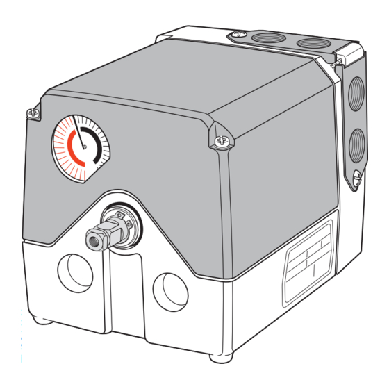
SQM5... reversing actuators are used for the positioning of flow control valves, butterfly
valves, dampers, or any application requiring rotary motion. The SQM5... actuators
accommodate control input signals of 4 to 20 mA, 0 to 135 Ω, 0 to 10 Vdc, 0 to 20 mA,
position proportional and floating control. The available output signals include
4 to 20 mA, 0 to 135 Ω, 0 to 10 Vdc, 0 to 20 mA, and 0 to 1000 Ω. SQM5... actuators
are available with up to six internal, easily adjustable switches.
A selection of exchangeable circuit boards provide a variety of functions including
auto/manual selector switch, manual forward/reverse toggle switch, zero and span
adjustment, parallel or master/slave operation, split range control, input signal override,
and selectable electronic linearization.
The SQM5... is engineered for precision. It is particularly well suited for applications
requiring a high degree of modulating accuracy and repeatability. Drive shaft play is
limited to 0.3° with a modulating accuracy of 250 repositions through 90° of travel.
The SQM5... actuator may be mounted in any position. A selection of mounting
brackets and shafts provides installation flexibility and allows for the simple
replacement of most competitive actuators.
•
Modulating accuracy of 250 repositions through 90°
•
Two limit switches, plus up to four internal auxiliary switches
•
Fully closed "economy position" switch
•
Drive shaft and cam drum disengagement clutches
•
Auto/manual switch, manual control forward/reverse toggle switch
•
UL, CSA approved 24 and 110 Vac versions
•
CE approved 220 Vac versions
•
Field reversible clockwise (cw) or counterclockwise (ccw) operation
•
Various torque ratings and running times available
•
Selection of field exchangeable single-ended and dual-ended shafts
•
Mounting brackets to replace competitive actuators
Technical Instructions
Document No. 155-517P25
Siemens Building Technologies, Inc.
July 9, 2007
Table of Contents

Related Manuals for Siemens SQM5


Summary of Contents for Siemens SQM5
-
Page 1: Features
The available output signals include 4 to 20 mA, 0 to 135 Ω, 0 to 10 Vdc, 0 to 20 mA, and 0 to 1000 Ω. SQM5… actuators are available with up to six internal, easily adjustable switches. -
Page 2: Application
• Adjustable input signal override function Application SQM5… actuators are uniquely suited for both industrial and commercial applications. The high level of accuracy permits precise modulating control of industrial process and process heating applications, often significantly enhancing performance and product quality. -
Page 3: Table Of Contents
Product Numbers Product numbers for pre-assembled UL/CSA/CE-approved actuators, Table 1 Page 4 Product numbers for accessories, Table 2 Page 5 SQM5… Product Number Identification Legend Page 6 Installation and Operating Instructions Shaft Installation Page 7 Rotational Direction Verification Page 8... -
Page 4: Product Numbers
Technical Instructions SQM5… Reversing Actuators Document No. 155-517P25 July 9, 2007 Table 1. Product Numbers for Pre-assembled Actuators. Product Numbers Running Product Number Torque Input Control Signals Time [lb-in] 90°@ 60 110 V 220 V 24 V Hzsec SQM50.261R1G3 SQM50.261R1G3R SQM50.264R1A... - Page 5 ASZ12.803 and ASZ12.30 1000 , 90° adaptable to Eclipse butterfly valves. Ω ASZ12.833 and ASZ12.33 1000 , 135° ASK33.9 mounting kit for direct attachment to Siemens Ω ASZ22.803 and ASZ22.30 1000/1000 double VKF41... butterfly valve. (Shaft AGA58.1 potentiometer, 90° required) Ω...
-
Page 6: Sqm5
Document No. 155-517P25 July 9, 2007 Product Number Identification Legend For actuator identification only. To select product numbers for ordering, see Table 1. Figure 1. SQM5… Product Number Identification Legend. SQM5 Actuator family Torque in-lb @ 60 (50) Hz. 90 for 8 (10) sec. running time 0 140 for 12 (15), 25 (30), 37 (45) sec. -
Page 7: Installation And Operating Instructions
SQM5… Reversing Actuators Technical Instructions Document No. 155-517P25 July 9, 2007 Installation and SQM5… actuators are sometimes shipped without the shaft installed. To install the selected shaft: Operation Instructions 1. Loosen the two screws on the actuator cover corners. See Figure 2. -
Page 8: Rotational Direction Verification
To field reverse the direction of rotation, see Service Guide, “Reversing Rotational Direction”. Actuator Mounting SQM5… actuators can be mounted in any orientation using the four 1/4"-20 UNC tapped holes located on the bottom corners of the actuator base. Optional base mounting brackets are available. See Table 2. -
Page 9: July
Position Indicating Dial Adjustment The actual position of the SQM5… actuator is indicated by the gray actuator position indicating pointer (see Figure 6). The position is also displayed by the indicating dial through the housing’s window. Ensure that the actuator position indicating dial is aligned with the actuator position scale. -
Page 10: Wiring Connections
Document No. 155-517P25 July 9, 2007 Wiring Connections NOTE: SQM5… actuators require a single source, single phase power supply. Wiring connections vary depending on which AGA56…. circuit board is installed. AGA56.1… circuit boards. Manual Operation See Figures 7 and 8. -
Page 11: Aga56.41/42/43
SQM5… Reversing Actuators Technical Instructions Document No. 155-517P25 July 9, 2007 Wiring, Continued MAN. AUTO. AGA56.1A97 Figure 8. AGA56.1A97 Terminal/Auto-Manual Board. Manual Operation AGA56.41/42/43… Circuit Boards. 1. Set the AUTO/MAN switch in the MAN position. 2. Connect ground to the screw located below the shaft release button. -
Page 12: Basic Functional Diagram Of Aga56.4
Technical Instructions SQM5… Reversing Actuators Document No. 155-517P25 July 9, 2007 Wiring, Continued AGA56.4... AGA56.41... ("G" board 4...20 mA) (+2 V) AGA56.42... 135 Ohm ("H" board 0-135 Ohm) 0...2 V AGA56.43... ("K" board 0...10 V) AUTO shown in actuator switch... -
Page 13: Aga56.9
SQM5… Reversing Actuators Technical Instructions Document No. 155-517P25 July 9, 2007 AGA56.9… Circuit Manual Operation Boards Set the AUTO/MAN switch in the MAN position. See Figures 11 and 12. Connect ground to the screw located below the shaft release button. -
Page 14: Basic Functional Diagram Of Aga56.9
Technical Instructions SQM5… Reversing Actuators Document No. 155-517P25 July 9, 2007 Wiring, Continued AGA56.9... SHIFT 4...20 mA (+2 V) 25% 50% 75% MAX 0...3 0...3 0...3 135 Ohm 0...2 V 4...20 mA 0...10 V 0...3 0...20 mA 4...20 mA 0...20 mA 0...10 V... -
Page 15: Modulation Adjustment
SQM5… Reversing Actuators Technical Instructions Document No. 155-517P25 July 9, 2007 Modulation Adjustment The blue trim potentiometers allow the adjustment of the minimum (zero) and maximum (span) positions. See Figures 10 and 12. The factory setting of the MIN trim potentiometer is rotated fully counter clockwise. -
Page 16: Cover Installation
Technical Instructions SQM5… Reversing Actuators Document No. 155-517P25 July 9, 2007 Lift the two screws on the cover corners and slide the cover end into the grooves Cover Installation at the gear end of the actuator. See Figure 14. Press the cover into place and then press the screws inward and tighten. See Figure 15. - Page 17 U4 and Y0.) See Figure 16. NOTE: It is possible to configure the actuator for split range operation 12 to 4 mA and 20 to 12 mA. Consult your authorized Siemens Building Technologies combustion products sales representative for details. 25% 50% 75% MAX 0...3...
-
Page 18: Sqm5X.xxxxxgx Actuators
Technical Instructions SQM5… Reversing Actuators Document No. 155-517P25 July 9, 2007 Features of SQM5x.xxxxxGx actuators contain the AGA56.41A… circuit board with terminals Y- and SQM5x.xxxxxGx, Y+ for 4 to 20 mA modulating input. SQM5x.xxxxxHx, SQM5x.xxxxxHx actuators contain the AGA56.42A… circuit board with terminals Y, M SQM5x.xxxxxKx... - Page 19 SQM5… Reversing Actuators Technical Instructions Document No. 155-517P25 July 9, 2007 Reversing Rotational Direction, Continued POSITION POSITION INDICATION INDICATION POINTER POINTER POSITION INDICATION POINTER POSITION INDICATION POINTER Clockwise Counterclockwise Figure 17. Reversing Rotational Direction on the ASZ Potentiometer. GEAR WITH MARK "1" FOR GEAR WITH MARK "0"...
-
Page 20: Shaft Installation
Disconnect the power supply to the actuator before replacing the circuit boards. The black circuit board mounting bracket, installed on the inside base of the SQM5… actuator has four vertical, slotted circuit board supports. Remove the terminal section and circuit board(s) from the mounting bracket. - Page 21 SQM5… Reversing Actuators Technical Instructions Document No. 155-517P25 July 9, 2007 AGA56.41/42/43 5. Re-install the actuator motor capacitor. Circuit Board See Figure 20. Installation, 6. Gently guide the terminal section into Continued the support slots and slide the terminal board downward until both supports snap into place.
-
Page 22: Aga56.9A
Figure 22. AGA56.9A… 1. Remove the ASZ... potentiometer if Circuit Board already installed on the SQM5... Installation actuator. See Potentiometer Removal/Installation Instructions. 2. Remove the AGA56.9A… circuit boards from the packaging. The three separate AGA56.9A circuit boards are... - Page 23 SQM5… Reversing Actuators Technical Instructions Document No. 155-517P25 July 9, 2007 AGA56.9A… 4. Guide the base circuit board from the Circuit Board switch housing side of the actuator into Installation, Continued the bottom of the circuit board mounting bracket. See Figure 23.
-
Page 24: Aga56.1A97
Technical Instructions SQM5… Reversing Actuators Document No. 155-517P25 July 9, 2007 AGA56.9A… 8. Gently guide the L-shaped circuit Circuit Board board containing the three blue trim Installation, Continued potentiometers into the vertical support VIII slots located on the cam drum side of the actuator. -
Page 25: Potentiometer Removal/Installation
SQM5… Reversing Actuators Technical Instructions Document No. 155-517P25 July 9, 2007 Potentiometer 9. Remove the white plastic actuator position-indicating dial by gently pulling while Removal rotating in the clockwise direction. See Figure 6. 10. Disconnect the blue, black and brown wire from the potentiometer terminal block. See Figure 17. -
Page 26: Specification Data
Technical Instructions SQM5… Reversing Actuators Document No. 155-517P25 July 9, 2007 Specifications SQM5... Reversing actuator Agency approvals UL, CSA, CE SQM5... Reversing Operating voltage 24 Vac +10%-15% Actuator 110 Vac-15% to 120 Vac +10% 220 Vac-15% to 240 Vac +10%... - Page 27 SQM5… Reversing Actuators Technical Instructions Document No. 155-517P25 July 9, 2007 Conduit connection Two removable inserts with two Specifications 1/2-inch NPSM threads. Each insert allows insertion of entire SQM5... Reversing cable tree for easy servicing Actuator, Continued Gears and bearings...
- Page 28 Technical Instructions SQM5… Reversing Actuators Document No. 155-517P25 July 9, 2007 Specifications, continued AGA56.43A… AGA56.43A… Electronic circuit boards Same specifications as AGA56.41A except: Input signal 0 to 10 Vdc Impedance ≥100K Ω Voltage input AGA56.9A… Multi function electronic Single potentiometer AGA56.9A...
-
Page 29: Dimensions
SQM5… Reversing Actuators Technical Instructions Document No. 155-517P25 July 9, 2007 Dimensions The first dimension given is measured in inches. Millimeters are shown in parentheses. 1-3/16 (16) (30) Pg 13.5 / 1/2" ALLOW 3.5" SPACE FOR NPSM COVER REMOVAL 1-3/16... - Page 30 Technical Instructions SQM5… Reversing Actuators Document No. 155-517P25 July 9, 2007 Dimensions, Continued 6-7/16 (164) 11/16 (18) 4-1/16 9/16 (103.3) (14.5) 4-7/8 AGA57.3 (123.8) 4-7/16 3-1/8 (113) (80) 4 X 1/4 4 X 1/4 Figure 29. Mounting Bracket AGA57.3. 7-5/16...
- Page 31 Information in this publication is based on current specifications. The company reserves the right to make changes in specifications and models as design improvements are introduced. Other product or company names mentioned herein may be the trademarks of their respective owners. © 2007 Siemens Building Technologies, Inc. Siemens Building Technologies, Inc.