Table of Contents
Available languages
Available languages
Owner's Manual
IC""FTSMeN'I
FRONT TINE TILLER
5.0 HP
24 Inch Tine Width
Model No.
917.291480
This product has a low emission engine which operates
[_
differently
from previously
built engines. Before
start the
you
engine, read and understand
this Owner's Manual.
IMPORTANT:
Read and follow all Safety
Rules and Instructions before
operating this equipment.
Sears, Roebuck and Co., Hoffman Estates, IL 60179 U.S.A.
Visit our Craftsman website:www.sears.com/craftsman
Table of Contents

Related Manuals for Craftsman 917.291480


Summary of Contents for Craftsman 917.291480
- Page 1 Before start the engine, read and understand this Owner's Manual. IMPORTANT: Read and follow all Safety Rules and Instructions before operating this equipment. Sears, Roebuck and Co., Hoffman Estates, IL 60179 U.S.A. Visit our Craftsman website:www.sears.com/craftsman...
- Page 2 LIMITED ONE YEAR WARRANTY ON CRAFTSMAN TILLER For one (1) year from date of purchase, when this Craftsman Tiller is maintained, lubricated, and tuned up according to the operating and maintenance instructions in the owner's manual, Sears will repair free of charge any defect in material or workmanship.
- Page 3 • Use extension cords and receptacles • Do not overload the machine capacity as specified by the manufacturer for all by attempting to till too deep at too fast units with electric drive motors or elec- a rate. tric starting motors. •...
- Page 4 PRODUCT SPECIFICATIONS CUSTOMER RESPONSIBILITIES Gasoline = Read and observe the safety rules. 3 Qts = Follow a regular schedule in main- Unleaded Capacity: taining, caring for and using your tiller. Regular • Follow the instructions under the "Main- SAE 30 OiI(API-SF-SJ): tenance"...
- Page 5 Your new tiller has been assembled at the factory with the exception of those parts left unassembled for shipping purposes. To ensure safe and proper operation of your tiller all parts and hardware you assemble must be tightened securely. Use the correct tools as necessary to insure proper tightness.
- Page 6 INSTALL DEPTH STAKE UNPACK CARTON & INSTALL ASSEMBLY HANDLE 1. Loosen nut "A". A(_CAUTION: Be careful of exposed sta- ples when handling or disposing of carton- 2. Insert stake support between engine ing material. bracket halves with stake spring down. IMPORTANT: When unpacking and as- 3.
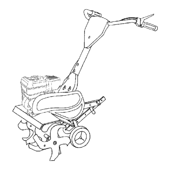
- Page 7 KNOW YOUR TILLER READ THIS OWNER'S MANUAL AND SAFETY RULES BEFORE OPERATING YOUR TILLER Compare the illustrations with your tiller to familiarize yourself with the locations of var- ious controls and adjustments. Save this manual for future reference. ORWARNING Forward Tine Control Control Control...
- Page 8 The operation of any tiller can result in foreign objects thrown into the eyes, which can result in severe eye damage. Always wear safety glasses or eye shields before starting your tiller and while tilling. We recommend standard safety glasses or a wide vision safety mask worn over spectacles. HOWTO USE YOUR TILLER WHEELS Know how to operate all controls before...
- Page 9 4. Tilt tiller back on its wheels and then TO START ENGINE re-level. _I_CAUTION: Keep tine control in "OFF" 5. With engine level, refill to point of over- position when starting engine. flowing if necessary. Replace oil filler When starting engine for the first time or plug.
- Page 10 BREAKING IN YOUR TILLER • You will find tilling much easier if you leave a row untilled between passes. Break-in your belt(s), pulleys and tine con- Then go back between tilled rows There trol before you actually begin tilling. are two reasons for doing this. First, •...
- Page 11 / Ig SCHEDULE FILL IN DATES AS YOU COMPLETE _O_/._?_; SERVICE DATES R EGU LAR SERVICE /_/_/_/z_/ Check Engine Oil Level Change Engine Oil 1_1,2 Oil Pivot Points Inspect Spark Arrester / Muffler Inspect Air Screen Clean or Replace Air Cleaner Cartridge Clean Engine Cylinder Fins...
- Page 12 _lLCAUTION:Disconnect spark plug 5. Refill engine with oil. See "FILL ENGINE WITH OIL" in the Operation wire before performing any maintenance section of this manual. (except carburetor adjustment) to prevent accidental starting of engine. Prevent fires! Keep the engine free of grass, leaves, spilled oil, or fuel.
- Page 13 type and gap setting are shown in "PROD- Muffler UCT SPECIFICATIONS" on page 4 of this manual. TRANSMISSION Your transmission is sealed and will not require lubrication unless serviced. CLEANING Do not clean your tiller when the engine and transmission are hot.
- Page 14 NARROW TILLING/CULTIVATING NOTE: If "ON" position check required 12-3/4" PATH adjustment, recheck "OFF" position ad- justment to insure tines do not rotate when • Remove outer tines. control is "OFF" (up). Tine Control "OFF" Position Inner Tines Onl NOTE: When reassembling outer tines, Tine Control Cable be sure right tine assembly...
- Page 15 CHECK TINE OPERATION ENGINE 4. See "TINE OPERATION CHECK" in Maintenance, repair, or replacement this section of manual. the emission control devices and systems, 5. Replace belt guard which are being done at the customers ex- pense, may be performed by any non-road Belt Guide engine repair establishment or individual.
- Page 16 Immediately prepare your tiller for storage NOTE: Fuel stabilizer is an acceptable at the end of the season or if the unit will alternative in minimizing the formation of not be used for 30 days or more. fuel gum deposits during storage. Add _ILCAUTION: Never store the tiller with stabilizer to gasoline in fuel tank or stor- gasoline in the tank inside a building...
- Page 17 TROUBLESHOOTING CHART: See appropriate section in manual unless directed to Sears service center PROBLEM CAUSE CORRECTION Will not start 1. Out of fuel. 1. Fill fuel tank. 2. See "TO START ENGINE" 2. Engine not "CHOKED" properly. in the Operation section. 3.
- Page 18 TROUBLESHOOTING CHART: See appropriate section in manual unless directed to Sears service center CAUSE PROBLEM CORRECTION 1. Low oil level/dirty oil. 1. Check oil level/change oil. Engine overheats 2. Dirty engine air screen. 2. Clean engine air screen. 3. Dirty engine. 3.
- Page 19 Programa De Mantenimiento ....... 28 GARANTfA LIMITADA DE UNO AI_IO PARA LA CULTIVADORA CRAFTSMAN Por un (1) aEo, a partir de la fecha de compra, cuando esta Cultivadora Craftsman se mantenga, lubrique y afine segt]n las instrucciones para la operaci6n y et mantenimiento en el manual del dueEo, Sears repararA, gratis, todo defecto en el material y la mano de obra.
- Page 20 OPERACION • Use solamente accesorios y aditamentos para la cultivadora aprobados por el fabri- • No ponga ni las manos ni los pies cerca o cante. debajo de las piezas rotatorias. • Nunca opere la cultivadora sin buena visibili- • Tenga mucho cuidado cuando opere o cruce dad o luz.
- Page 21 ESPECIFICACIONES DEL PRODUCTO RESPONSABILIDADES DEL CLIENTE • Lea y observe las reglas de seguridad. Capacidad de 3 Cuartos • Siga un programa regular de mantenimiento, Gasolina: Sin plomo, Regular cuidado y uso de su cultivadora. Aceite (API-SF-SJ): SAE 30 (Sobre 32°F) •...
- Page 22 Su cultivadora nueva ha sido montada en la f&brica, con la excepci6n de aquellas partes que se dejaron sin montar per razones de env/o. Para asegurarse que la cultivadora operar& en forma segura y adecuada, todas las partes y los artfculos de ferreterfa que monte tienen que estar apre- tados en forma segura.
- Page 23 INSTALACION DEL CONJUNTO DE LA DESEMPAQUE DE LA CAJA CARTON E INSTALACION DEL MANGO ESTACA DE PROFUNDIDAD 1. Afioje la tuercas"A". A(_PRECAUCI(_N: Tenga cuidado con las Inserte el soporte de la estaca entre las grapas expuestas cuando maneje o deseche mitades del puntal del motor, con el resorte los materiales de la caja de cart6n.
- Page 24 CONOZCA SU CULTIVADORA LEA ESTE MANUAL DEL DUEI_IO Y LAS REGLAS DE SEGURIDAD ANTES DE OPERAR SU CUTIVADORA Compare las ilustraciones con su cultivadora para familiarizarse con la ubicaci6n de los diversos controles y ajustes. Guarde este manual para referencia en el futuro. Estos simbolos pueden apareser sobre su cultivadora en la literatura proporcionada con el producto.
- Page 25 La operaci6n de cualquier cultivadora puede hacer que salten objetos extraSos dentro de sus ojos, to que puede producir daSos graves en 6stos. Siempre use anteojos de seguridad o protecciones para los ojos antes de hacer arrancar su cuttivadora o mientras est6 labrando con 611a.
- Page 26 5. Conel motor nivelado, vuelva a Ilenarlo PARA HACER ARRANCAR EL MOTOR hastael puntodederramarse, si es necesa- _PRECAUCI(_N: Mantenga la barra de rio.Vuelva a colocar eltap6ndeldep6sito control de la impulsi6n en la posici6n "DESEN- derelleno deaceite. GANCHADO" cuando haga arrancar el motor. •...
- Page 27 RODAJE DE SU CULTIVADORA • Va a descrubrir que el labrado se facilita si deja una ilia sin labrar entre las pasadas. Use su(s) correa(s), las poleas y el control de Entonces vuelva de nuevo entre las filas de los brazos antes de empezar a labrar. cultivo.
- Page 28 PROGRAMA MANTENIMIENTO /iZ!/I/I/ LLENE LAS FECHAS DE MEDIDA QUE COMPLETE DE SERVICIO SERVICIO REGULAR Revisar el nivel del aceite del motor Cambiar el aceite del motor _11_,_ Aceitar los puntos de pivote lnspeccionar el supresor del silenciador lnspeccionar la rejila de aire Limpiar/cambiar el cartucho...
- Page 29 Despu6s de que el aceite se haya drenado A(_PRECAUCl6N: Desconecte el alambre de completamente, vuelva a colocar et tap6n la bujia antes de dar mantenimiento (excepto del drenaje del aceite y apri6telo en forma por el ajuste del carburador) para evitar que el segura.
- Page 30 BUJ|A Aletas del cilindor Cambie las bujfas al comienzo de cada temporada de cultivo, o despu6s de 50 horas Silenciador de uso, Io que suceda primero. El tipo de bujfa y la abertura aparece en las "ESPECIFICACIONES DEL PRODUCTO ° en a del ventilador la p&gina 21 de este manual.
- Page 31 CULTIVO/LABRADO ESTRECHO - PASO DE Si los brazes no rotan, el alambre interior del cable de control estA demasiado suelto. 12-3/4" Suelte la abrazadera del cable y empuje el • Remueva los brazos extedores. cable hacia arriba para remover la soltura y vuelva a apretar la abrazadera.
- Page 32 PARA CAMBIAR LA CORREA V MOTOR Cambie ta correa V si se ha estirado consid- El mantenimiento, la reparaci6n, o el reemplazo erablemente o si est& partida o si los bordes de cualquier dispositivos o sistemas del control estAn desgastados. de ta emisi6n, los cuales sean hechos al costo La protecci6n de ta correa tiene que del cliente, pueden set realizados por cualquier...
- Page 33 AVISO: El estabilizador de combustible es una Inmediatamente prepare su cultivadora para el atmacenamiento al final de la temporada o si la altemativa aceptable para reducir a un minimo unidad no se va a usar per 30 dias o m&s. la formaci6n de dep6sitos de goma en et com- _PRECAUCI(_N: Nunca almacene la cultiva-...
- Page 34 IDENTIFICACI(_N DE PROBLEMAS: Vea la seccidn apropiada en el manual a menos que estd dirigido a un centro de servicio Sears. CORRECCION PROBLEMA CAUSA No arranca 1. Sin combustible. 1. Ltene el estanque de combustible. 2. Motor sin la"ESTRANGU- 2. Vea "PARA ARRANCAR MOTOR"...
- Page 35 IDENTIFICACION DE PROBLEMAS: Vea la seccibn apropiada en el manual a menos que estd dirigido a un centro de servicio Sears. PROBLEMA CORRECCION i CAUSA El motor se 1. Revise el nivel del aceite/cambie Nivel del aceite bajo/aceite calienta dem sucio.
- Page 36 TILLER - - MODEL NUMBER 917.291480 HANDLES KEY PART PART NO. NO. DESCRIPTION DESCRIPTION 137118 Panel, Control 12000027 Ring, Clip 9266R Grip, Handle 12000059 Retainer, Ring 72010520 Belt 5/16-18 x 2-1/2 98000129 Nut, Flange STD533107 Bolt, Carriage 5/16-18x3/4 73970500 Lecknut, Flange 5/16-18 UNC 181476 Assembly, Panel and Tube 152094...
- Page 37 TILLER - - MODEL NUMBER 917.291480 BELT GUARD AND PULLEY ASSEMBLY PART KEY PART DESCRIPTION NO. NO. DESCRIPTION 23230506 Screw Set 5/16-18 x 3/8 Patch 12000028 Ring, Retainer 130812 151223 Sheave, Transmisison Sheave, Engine 86777 Screw, Tap Hex Head 12000035 Ring, Klip 74610812 Bolt, Hex Head 1/2-20 x 3/4...
- Page 38 TILLER - - MODEL NUMBER 917.291480 WHEEL AND DEPTH STAKE ASSEMBLY 19 18 KEY PART PART NO. NO. DESCRIPTION DESCRIPTION 9194R Pin, Clevis 5388J Spring, Stake 74760520 121117X Bolt, Shoulder Bolt, He>
- Page 39 TILLER - - MODEL NUMBER 917.291480 TINE ASSEMBLY KEY PART PART NO. NO. DESCRIPTION DESCRIPTION 156926 Tine, Oute£R.H. 156925 Tine, Outer, LH. 3146R 4929H Pin, Clevis Retainer, Spring Zinc 156924 Tine, lnner, R.H. NOTE: All component dimensions given in U.S. 156923 Tine, lnner, LH.
- Page 40 TILLER - - MODEL NUMBER 917.291480 TRANSMISSION PART PART DESCRIPTION DESCRIPTION 74760524 Bolt, Hex 5/16-18 x 1-1/2 Gr. 2 73970500 Nut, Lock Hex Flange STD523732 5/16-18 UNC Bolt, Fin, Hex 3/8-16 x 3-1/4 STD551037 Washer 13/32 x 13/16 x 11 19091412 Washer 9/32 x 7/8 x 12 Ga.
- Page 41 TILLER - - MODEL NUMBER 917.291480 DECALS PART DESCRIPTION 186015 Decal, Logo 166215 Decal, Belt Guard Tine Shield HP 137539 Decal, Cntrl Phi Inst. 120431X Decal, Hand Placement 176783 Decal, Engine Oper. 120075X Decal, Warning, Rotating Tines 167156 Decal, Engine B&S Intek 171078 Decal, Rewind Intek 162215...
- Page 42 TILLER - - MODEL NUMBER 917.291480 ENGINE, BRIGGS & STRATTON -- MODEL NUMBER 126402,TYPE NO. 0206-E1 3s® 238© 15A@ 718 _ "k REQUIRES SPECIALTOOLS 32_3_ TO INSTALL. SEE REPAIR 742 _ 2_._ INSTRUCTION MANUAL. 11058 OWNER S MANUAL I...
- Page 43 TILLER - - MODEL NUMBER 917.291480 ENGINE, BRIGGS & STRATTON -- MODEL NUMBER 126402,TYPE NO. 0206-E1 633A O 692 _ 186_ 276_ 977 CARBURETOR GASKET SET 276 _ 163% 633A G 121 CARBURETOR OVERHAUL KIT 163% 276_ 104_ 127_ 633_ 633A_ 358 ENGINE GASKET SET 1022_...
- Page 44 TILLER - - MODEL NUMBER 917.291480 ENGINE, BRIGGS & STRATTON -- MODEL NUMBER 126402,TYPE NO. 0206-E1 209_ 209_ 2221 427_ 271_ 836 % 300_ 425_ 190_ 971_...
- Page 45 TILLER - - MODEL NUMBER 917.291480 ENGINE, BRIGGS & STRATTON -- MODEL NUMBER 126402,TYPE NO. 0206-E1 65_56 1211 1210 I 1036 EMISSIONS LABEL] 1005 305_ 1095 VALVE GASKET 868_...
- Page 46 TILLER - - MODEL NUMBER 917.291480 ENGINE, BRIGGS & STRATTON -- MODEL NUMBER 126402,TYPE NO. 0206-E1 PART PART DESCRIPTION DESCRIPTION 693811 Cylinder Assembly 690024 Shaft-Throttle 299819 • Seal-Oil (Magneto Side) 398185 Kit-Idle Speed 693643 Head-Cylinder 691242 {3Pin-Float Hinge 695166 ,+Gasket-Cylinder Head 692567 Valve-Choke 692600...
- Page 47 TILLER - - MODEL NUMBER 917.291480 ENGINE, BRIGGS & STRATTON -- MODEL NUMBER 126402,TYPE NO. 0206-E1 PART PART DESCRIPTION DESCRIPTION 690345 Screw (Cylinder Shield) 692566 Gear-Idler 690662 Nut (Flywheel) 694258 Retainer 692605 Armature-Magneto 694544 Stud (Rocker Arm) 691061 Screw (Armature Magneto) 693583 Guard-Muffler 491055...
- Page 48 Get it fixed, at your home or ourst Your Home For repatr- in your home - of all major brand apphances, lawn and garden equtpment, or heahng and coohng systems, no matter who made it, no matter who sold it! For the replacement parts, accessones owner's manuals that you need to do-it-yourself.