Table of Contents
f
Save This Manual
For Future Reference
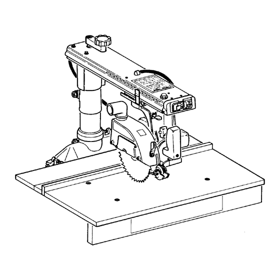
owner's
manual
MODEL NO.
113.234700
81/4-1NCH
RADIAL SAW
Serial
Number
Model and serial numbers
may be found at the
rear of the base.
You shouicl record both
model and serial number in
a safe place for future use.
FOR YOUR
SAFETY:
READ ALL
INSTRUCTIONS
CAREFULLY
SEARS / CRRFTSM RN®
81/4-INCH
RADIAL SAW
• assembly
• operation
• repair parts
\
i/
Sold by SEARS, ROEBUCK AND CO., Chicago,
IL 60684
U.S.A.
Part No. SP5300
Printed
in U.S.A
Table of Contents

Related Manuals for Craftsman 113.234700


Summary of Contents for Craftsman 113.234700
- Page 1 Save This Manual For Future Reference owner's manual MODEL NO. 113.234700 81/4-1NCH RADIAL SAW Serial Number Model and serial numbers SEARS / CRRFTSM RN® may be found at the rear of the base. You shouicl record both model and serial number in a safe place for future use.
- Page 2 ........Maintenance ........Troubleshooting ........Repair Parts ........Index ......... FULL ONE YEAR WARRANTY ON CRAFTSMAN RADIAL ARM SAW If within one year from the date of purchase, this Craftsman Radial Saw fails due to a defect in material or workmanship, Sears will repair it, free of charge.
- Page 3 Safety This manual has safety information Major Hazards instructions to help users eliminate reduce the risk of accidents and injuries, Three major hazards are associated with using the radial arm saw for ripping. including: They are outfeed zone hazard, kickback, 1.
- Page 4 Safety Kickback Hazard Kickback is the uncontrolled propelling kWARNING of the workpiece back toward the user during ripping. The cause of kickback is the binding pinching of the blade in the workpiece. Several conditions can cause the blade to bind or pinch. KICKBACKI!I_ When a workpiece...
- Page 5 Safety Safety Instructions Read and follow these safety instruc- tions. Personal Safety Instructions 1. Wear safety goggles labeled "ANSI Z87.1" on the package. It means the gog- gles meet impact standards set by the American National Standards Institute. Regular eyeglasses are not safety gog- gles.
- Page 6 Safety 2. Turn saw off, remove yellow key, and unplug before leaving work area. Do not leave saw until blade has stopped spinning. 3. Make work area child-proof: remove yellow key to prevent accidental start- up; store key out of sight and reach; lock work area.
- Page 7 Safety 3. Unplug saw before doing main- tenance, making adjustments, correcting alignment, or changing blades. 4. Do not force saw. Use saw, blades and accessories only as intended. 5. Have yellow key out and saw switched "off' before plugging in power cord. 6.
- Page 8 Safety Workpiece Safety Instructions 1. Cut only one workpiece at a time. Do not stack workpieces or lay them edge to edge. 2. Rip only workpieces longer than the diameter of the blade. Do not rip workpieces that are shorter than the diameter of the blade being used.
- Page 9 Safety Blade Safety Instructions 5. Do not overtighten nut when securing blade to saw because blade collar could 1. Use only blades marked for at least warp. 5500rpm. 6. Do not turn saw on and off in rapid se- 2. Use only blades 8v4 inches in quence because blade can loosen.
- Page 10 Safety _I_WARNING On the infeed side of the guard is this safety label to alert you to kickback: KICKBACKIII_ _IkDANGER On the side surface of the motor, visible from the infeed side when the saw is in a rip position, is this safety label to alert you to outfeed zone hazard: DANGER...
- Page 11 Safety ILWARNING Near the saw handle is this safety label to alert you to thrown objects and to remind you to wear safety goggles: On the top of the radial arm is this general safety instruction label: 1. Read manual before using saw. 2.
- Page 12 Assembly It is important for your safety and to get accurate cuts that you put the saw together according to these instructions. Identifying Parts The following parts are included: Note: Before beginning assembly, check that all parts are included. If you are miss- ing any part do not assemble saw.
- Page 13 Assembly "e4_ © The following hardware is included: A. Phillips Pan Head Screw, 1/4" G. Lock Washer, Y16" diameter..12 diameter by 1" ........4 H. Lock Washer, _" diameter ..4 B. Carriage Bolt, _6" diameter I. Nut, _46"........12 by 3/4"...
- Page 14 Assembly Tools Needed for Assembly and Alignment Framing Square Wrench Hex Wrench 3/8' Wrench 3/16" Hex Wrench 12-Inch Comblnetlon Square 7/16 _ Wrench 1/2" Wrench Screwddver #2 Phillips 3/4" Wrench Socket Extension 1/'Z' Socket Socket Wrench Assembly Steps Follow these steps in order. WARNING: Bilu Plugging...
- Page 15 Assembly 2. Position base so that edge is offwork surface. 3. From inside surface, put carriage bolt Table Clamp through slot in base and hold in place at Screw Mount highest point. Notch 4. Slide side frame into place on base so that table clamp screw mount fits into notch on side frame.
- Page 16 Assembly Do Not Remove Blade Carriage to Radial Arm These Screws Assembly Carriage Bearings Note: It may be easier to do this assembly with the parts still in the box because they are connected by a cord,"otherwise you Stop may need help to lift both parts out of the Screw box at the same time.
- Page 17 Assembly 5. Position radial arm so that arm is straight up in air. Lift blade carriage saw handle. CAUTION: Blade is exposed. 6. Slide blade carriage onto radial arm, so that carriage bearings fit into radial Lock arm track. Note: In correct orientation, single bearing is on left, two bearings are Lock on right as you look down radial arm.
- Page 18 Assembly Radial Arm to Base Assembly Miter Unlock Lock 1. Back out column retaining screw from base enough so column can clear when inserted. 2. Unlock miter lock. Pull out miter index pin and turn 90° to lock out. 3. Get grease packet. Being careful of sharp edges which may be present in base opening, evenly spread grease Column...
- Page 19 Assembly Making Radial Arm Parallel to Frame The radial arm must be parallel to the frame so that when lowered onto the table, the blade will be the same dis- tance from the table at all points. 1. Lock miter lock. 2.
- Page 20 Assembly 7. Lift front end of radial arm and slide front table between radial arm and frame, towards front. Do not let table edges rest in notches of side frame. 8. Leave front table in place. Wrench tighten rear bolt on each side where side frame attaches to base.
- Page 21 Assembly 2. Place table support against side frame so that rectangular openings line up with square openings in side frame, and Table Support Side Frame narrow edge is on top and outside. 3. Put bolt through square opening in side frame from inside surface. 4.
- Page 22 Assembly 2. Place table so that larger holes face up. Align table over middle and front holes in table supports. Note: Table will extend over front edge of frame. Larger 3. Drop flat washer into each hole, then Opening insert screw. From underneath surface, on end of each screw put lock washer, then nut.
- Page 23 Assembly Install Rip Scale Indicators, Table Clamp Screws, and Dust Elbow 1. Set out: Radial Arm -two rip scale indicators -two table clamp screws -two table clamp washers -dust elbow. . Rip Scale Blade Indicator Carriage 2. Slide one indicator onto each side of blade carriage.
- Page 24 Controls Rip Lock On-Off Switch Rip Scale Rip Indicator Bevel Index Pin Yellow Key Bevel Lock Control Pun_on Operation/Comment_ On-off Switch Turns motor on/off Pull on, push off Requires yellow key Allows saw to be switched on Insert into on-off switch, Yellow remove after turning saw off Elevation...
- Page 25 Controls Swivel Index Swivel Lock Miter Index Pin Miter Lock Table Clamp Screw Operation/Comments Pull to unlock; push to lock Swivel Lock Frees blade carriage to rotate Works with swivel index pin between tip and crosscut posi- tion; locks in place Push down and hold while After swivel lock is unlocked, Swivel Index Pin...
- Page 26 Controls Pawls/Spreader Lock Spreader Nut Operztion/Comment_ Move counterclockwise to -- Pawls/spreader Frees pawls/spreader to move Lock to desired position unlock, clockwise to lock Set pawls/spreader before rip- ping Pawl_spreader Reduce kickback by keeping Set as unit. See ripping set-up for details and illustrations. kerr open (spreader func- tion);...
- Page 27 Controls , Hold Down Lock Hold Down FuneHon Operation/Comment Hold Down Lock Move counterclockwise Frees hold down to move to unlock, clockwise to lock desired position; locks in place Set hold down before ripping With blade in table kerr and Hold Down Keeps workpiece from flutter- workpiece against blade,...
- Page 28 Alignment and Adjustment The saw and blade must be aligned cor- rectly for two reasons: 1) to make cuts accurate 2) to prevent binding of the blade and workpiece, which can cause jams, kick- backs, or thrown workpieces. _WARNING: Alignment and Adjustment Plugging in saw during...
- Page 29 Alignment and Adjustment Adiustable Adjusting Carriage Bearings Carriage. "_ Front Carriage Bearing Bearing The goal of this adjustment is to eliminate looseness between the car- riage bearings and the radial arm. The blade carriage should roll freely along the entire length of the radial arm, but with some resistance.
- Page 30 Alignment and Adjustment 3/16" Hex 5. Hold hex wrench in place and use vz" socket wrench to loosen nut on under- Wrench side of carriage just enough to allow ad- justable carriage beating screw to turn. (Nut is accessible through hole in direct line with hex wrench.) 6.
- Page 31 Alignment and Adjustment 6. Use elevation handle to raise and lower radial arm a few turns in each direction. Movement should be smooth but firm. If movement seems difficult, Arm Suppo_ slightly loosen 1/2-13hex bolt. 7. Position hands as in step 3. Feel for movement between column and arm support as you push radial arm side to side.
- Page 32 Alignment and Adjustment 5. Start with blade over highest point of table as found in step 4. Rotate blade by hand and use elevation handle to slowly lower radial arm until one tooth just touches table. Mark this tooth. 6. Tighten table support bolt that is in line with blade.
- Page 33 Alignment and Adjustment swivo, Squaring Blade Crosscut Travel The goal of this adjustment is to make accurate crosscuts. To do so, the blade must travel along the radial arm, per- F_"_ II_._zlr t_'_ --. _'_-SX.lf Miter Lock pendicular to the fence, otherwise, there will be a slight miter angle in all crosscuts.
- Page 34 Alignment and Adjustment Plate Squaring Blade to Table The goal of this adjustment is to make the blade perpendicular to the table so that cuts will be accurate; otherwise cuts will have a slight bevel angle. The Cover Plate bevel scale will also be adjusted. 1.
- Page 35 Alignment and Adjustment Table Clamp Screw Squaring Blade to Fence The goal in setting the blade perpen- dicular to the fence is to reduce the risk of kickback when ripping. This adjust- ment will also reduce splintering of the workpiece and burning of the kerr during ripping and crosscutting.
- Page 36 Alignment and Adjustment 5. Unlock swivel lock, but do not move Swivel Rip Lock swivel index pin. Use Yi6"hex wrench to Lock "Locked" loosen two adjusting screws under ear- riage. _ere are two access holes to these screws, one on each side of swivel handle.) Make adjustment by rotating motor.
- Page 37 Alignment and Adjustment spreader does not rest flat against fence, go to step 6. 6. Use v_"wrench to loosen both spreader nuts. Slide spreader against fence. Tighten spreader nuts. Spreader_ 7. Unlock pawls/spreader lock, raise paw!/spreader unit up to guard and lock in place.
- Page 38 Alignment and Adjustment Adjusting Out-Rip Scale Indicator 1. Unlock rip lock and pull blade car- riage forward. Unlock swivel lock, depress swivel index pin, and set blade carriage in out-rip position (motor towards fence). Lock swivel lock. 2. Push blade carriage back until blade is against fence.
- Page 39 Electrical Connections This tool is equipped with a two wire Motor Specifications cord and two prong plug which can be used in standard 120 volt A.C. outlets. The double insulated motor used in this No grounding of the tool is necessary. saw has the following specifications: The housing...
- Page 40 Crosscutting Thrown Workpiece _CAUTION: Workpiece could be picked up by spinning blade thrown. could be hit by thrown workpiece, or your fingers or hand could pulled into blade. To reduce risk of thrown workpiece: 1. Make sure installed fence is at least half as high as the workpiece, and never less than s/4".
- Page 41 Crosscutting Crosscutting Defined Straight Miter Bevel Compound Crosscutting is cutting a workpiece to length. The workpiece is held firmly against the fence, and the blade is pulled through the workpiece to make the cut. Straight, miter, bevel, and com- pound cuts can be made. Basic Crosscuts Crosscutting Safety...
- Page 42 Crosscutting Rolling Carriage _WARNING: When saw is turned on, blade can suddenly come toward you. reduce risk of this happening: 1. Keep one hand on saw handle when turning saw on. 2. Make sure saw slants slightly toward rear. If needed, put shim under front frame.
- Page 43 Crosscutting Crosscutting Hints Crossscutting Checklist 1. To extend the life of the table top, Refer to the following checklist before make an additional top out of v4" making crosscut kerfs or crosscutting. It plywood or masonite. Clamp or nail to will remind you of things to do to make original table top, section...
- Page 44 Crosscutting Kerfs A kerf or shallow cut is needed in the table and fence to serve as a path for the blade and to ensure that the blade cuts all the way through the workpiece. A kerr is needed for each different cutting path.
- Page 45 Crosscutting 7. Plug saw in. 8. Put yellow key in switch. 9. Grasp and hold onto saw handle, then 10. Slowly turn elevation handle dock- wise to lower radial arm until blade touches table, then continue to lower by half turn of elevation handle. 11.
- Page 46 Crosscutting Making Straight and Miter Crosscuts Follow these steps to make straight and miter crosscuts. Note: There are four in- dexed miter positions, 0°, 22_ ° right and left, and 45° right. To move to an indexed position, unlock miter lock and pull and hold out miter index pin while moving arm to desired angle.
- Page 47 Crosscutting 8. Plug saw in. 9. Put yellow key in switch. 10. Grasp and hold onto saw handle, Yellow Key then turn saw on. 11. Hold workpiece down and against fence, keeping hand at least 6" away from blade. 12. Hold hand in straight line with saw handle and pull blade through fence Fence and workpiece only far enough to com-...
- Page 48 Crosscutting Making Bevel and Compound Crosscuts Bevel Index Pin Follow these steps to make bevel and compound crosscuts. 1. Check that saw is unplugged, switch is "off' and yellow key is out. 2. Put fence between front table and spacer board. Tighten table clamps. Bevel Lock 3.
- Page 49 Crosscutting 9. Lower pawls to clear fence or workpiece, whichever is higher, by _". 10. Put yellow key in switch. 11. Grasp and hold onto saw handle, then turn saw on. Bevel Angle 12. Hold workpiece down and against fence, keeping hand at least 6"...
- Page 50 Ripping Ripping Defined Ripping is changing the width of a Middle Fence Position workpiece by cutting along its length. The workpiece is fed into the blade, which rotates in a fixed position, paral- lel to the fence, a set distance from the €'1 Ii &...
- Page 51 Ripping Workpiece Positioning Always set up so that the widest part of the workpiece is between the blade and fence. For example, ffyou want to rip 1" off a 10" wide workpiece, set the saw blade 9" from the fence. Widest Part of Workplece Push Sticks and Push Blocks...
- Page 52 Ripping Ripping Safety The hazards associated with ripping are outfeed zone hazard, kickback, wrong way feed, and thrown chips. This section explains these hazards and tells how to avoid them or reduce the risk of their happening. Read the ripping safety in- formation and instructions before...
- Page 53 Ripping Kickback Kickback is the uncontrolled propelling of the workpiece back toward the user during ripping. _WARNING: Kickback can happen when blade is WARNING pinched or bound by workpiece. Pinching or binding can happen when: • pawls and spreader are not used or not set correctly •...
- Page 54 Ripping To reduce risk of kickback: 1. Correctly set pawls and spreader. Spreader keeps workpiece from binding or pinching blade; pawls grab into workpiece to stop or slow kickback if one happens. 2. Check that spreader is in line with blade.
- Page 55 Ripping Wrong Way Feed Wrong way feed is ripping by feeding the workpiece into the outfeed side of &WARNING the blade. _WARNING: Rotational force of blade will pull workpiece through violently workpiece is fed in same direction as blade rotates (wrong way feed).
- Page 56 Ripping Pawls and Spreader Function The pawls and spreader must be set cor- rectly during tippingt to reduce the risk of kickback, to prevent wrong way feed, and to act as a partial barrier to the haz- ardous ouffeed side of the blade. The spreader tides in the workpiece kerr to keep it open.
- Page 57 Ripping Ripping Checklist Refer to the following checklist before making rip kerfs or ripping. It will remind you of things to do to make your cutting safer. Ripping Hints 4. Use the right blade for each job. 1. To extend the life of the table top, 5.
- Page 58 Ripping Kerfs A kerr or shallow cut is needed in the table to serve as a path for the blade and to ensure that the blade cuts all the way through the workpiece. A kerf is needed for each different cutting posi- tion.
- Page 59 Ripping 6. Unlock rip lock, position blade desired distance from fence, and lock rip lock. In-Rip Position 7. Turn elevation handle clockwise to lower blade until it just clears table. 8. Plug in saw, put yellow key in switch and turn saw on. 9.
- Page 60 Ripping Ripping Set-up Procedure Follow these steps before ripping. These steps must be repeated each time a dif- ferent thickness workpiece is ripped. 1. Check that saw is unplugged, switch is "oft", and yellow key is out. 2. Put solid (no kerfs) fence in desired position and tighten table clamps.
- Page 61 Ripping 11. Test spreader/pawl setting by push- ing workpiece toward ouffeed side to see that workpiece moves freely, then pulling toward infeed side to see that pawl grabs. If these conditions are not met, repeat steps 10 and 11 until they are.
- Page 62 Ripping Making Rip Cuts Follow these steps to make rip cuts: 1. Follow ripping set-up procedure. 2. Plug in saw, insert yellow key and turn 3. Stand at infeed side and out of line of workpiece, in case of kickback. Start and finish cut from infeed side.
- Page 63 Cutting Aides Cutting aides include fences, push sticks, auxiliary fences, push blocks, featherboards, and straight edges. Fences Fences are required for all saw opera- tions. Crosscutting requires fences with kerfs (slots) to match the path of the saw, be- cause the saw blade is pulled through the kerf in the fence to cut the workpiece.
- Page 64 Cutting Aides Push Sticks Push sticks must be used during ripping to push the workpiece through to com- plete cuts that would bring your hands too close to the blade. Use a push stick when the blade is set 2" or more from the fence.
- Page 65 Cutting Aides To make a push block: 314" Plywood 1. Use one piece of _/4"plywood and one piece of _" plywood. 2. Cut the a/4"plywood to 10" by 5". 3. Cut a triangular piece off each of two corners by marking with a pencil in and 1-1/4"...
- Page 66 Cutting Aides kerf closed, put binding pressure on the blade, and cause kickback. To make a featherboard: 1. Use solid (knot free) 3/4" lumber 5_" wide. -1/2 2. Miter crosscut at a 30 ° angle to 24". 3. Rip to make 5" long cuts about v'4" apart.
- Page 67 Accessories Accessories Safety • the blade is in its rearmost position 1. Use only accessories listed in this sec- • the guard is resting on the table so tion. Use of any other accessory or at- the leading and trailing teeth of the tachment might increase the risk of blade are not exposed from the sides.
- Page 68 Accessories Accessories for this Saw • Workpiece or cut-off pieces can be violently thrown by the blade. Wear These accessories are designed to fit safety goggles this saw. Read and follow instructions CAUTION: that come with accessory. Lower blade guard can get caught Item ........
- Page 69 Maintenance WARNING: Lubrication To avoid shock, burns, or lacera- Do not lubricate motor bearings. Motor tions from accidental start up of bearings are sealed and do not need saw, turn power switch off and un- added lubrication. plug saw before doing maintenance or servicing saw.
- Page 70 Maintenance Carriage Bearings Hold Down and Pawls/Spreader Locks The carriage should roll freely but with If the hold down or the pawl/spreader some resistance for the entire length of do not hold when locked, or if the lock travel. If the carriage moves too freely lever has to be turned more than 90°...
- Page 71 Maintenance Motor Brush Assemblies The motor brush assemblies that come with the saw will last about 100 cutting hours. Replace both carbon brushes when either has W' length or less of carbon left. To inspect brushes: Motor End 1. Check that saw is unplugged, switch is "off", and yellow key is out.
- Page 72 Maintenance Blade Changing To change the saw blade, follow these steps: 1. Check that saw is unplugged, switch is "oft", and yellow key is out. 2. Unlock rip lock, pull blade carriage out to end of radial arm, and lock rip lock.
- Page 73 Troubleshooting Motor Problem What to Do Possible Cause(s) Motor overheats or stalls Excessive feed rate when Slow rate of feed crosscutting or ripping Clean out sawdust from Improper motor cooling motor to allow normal air circulation Undersized extension cord Check wire gauge chart in Electrical Connections Inadequate house wiring Call your electrician...
- Page 74 Troubleshooting What to Do Possible Cause(s) Cutting Problem Crosscuts not accurate Crosscut travel not square See Squaring Blade with fence Crosscut Travel miter indexed positions. Arm not indexing properly See Miter Lock Assembly See Swivel Lock or Car- Carriage assembly loose on riage Bearings Adjustment anti...
- Page 75 Troubleshooting Possible Cause(s) What to Do Cutting Problem Board pulls away from Blade out of alignment Check alignment fence during ripping Workpiece strikes spreader Spreader not in line with See Alignment, Spreader blade during ripping Workpiece binds, smokes, Saw blade out of alignment Check alignment and motor slows Or stops Dull or incorrect blade...
- Page 76 Troubleshooting What to Do Saw Problem Possible Cause(s) Clean track Blade carriage does not Dirty track travel smoothly on arm Replace bearing Bad bearing Bearing set too tight See Adjustment, Carriage Bearings Worn arm track Replace radial arm Rip lock too tight See Adjustment, Rip Lock Table cannot be leveled...
- Page 77 Note: This page intentionally left blank.
- Page 78 Repair Parts PARTS LIST FOR 8 1/4" RADIAL ARM SAW MODEL NO. 113.234700 FIGURE 28 29 23 24 21 20 19...
- Page 79 Repair Parts PARTS LIST FOR 8 1/4" RADIAL ARM SAW MODEL NO. 113.234700 Always order by Part Number -- Not by Key Number FIGURE Part Description Part Description STD512510 *Screw-Pan Hd 1/4-20 x 1 STD551131 * Lockwasher-5/16 Washer-17/64 x 5/8 x 1/32 STD541031 *Nut-5/16-18 60128...
- Page 80 Repair Parts PARTS LIST FOR 8 1/4" RADIAL ARM SAW MODELNO. 113.234700 FIGURE...
- Page 81 Repair Parts PARTS LIST FOR 8 1/4" RADIAL ARM SAW MODEL NO. 113.234700 Always order by Part Number -- Not by Key Number FIGURE Part Description Part Description STD541462 *Nut-Lock 5/8-11 818711 Lever-Bevel Lock 60047 Washer-.630 x 1 x 1/32 STD551210 * Lockwasher-tnt N 10 815865...
- Page 82 Repair Parts PARTS LIST FOR 8 1/4" RADIAL ARM SAW MODEL NO. 113.234700 FIGURE 42__ 36., " 28..
- Page 83 Repair Parts PARTS LIST FOR 8 1/4" RADIAL ARM SAW MODEL NO. 113.234700 Always order by Part Number -- Not by Key Number FIGURE Part Description Part Description 818754 Relief-Strain STD551050 *Washer-17/32 x 1 x 1/16 818697 Cord-Motor 815992-1 Screw-Soc Cap TY"-FT" 803709 Connector-Wire 1/4-20 x 3/4...
- Page 84 Repair Parts PARTS LIST FOR 8 1/4" RADIAL ARM SAW MODEL NO. 113.234700 • 22 1 Always order by Part Number -- Not by Key Number FIGURE Part Description Part Description 63258 Elbow-Dust 818738 Bar-Anti Kickback 818741 Cover-Connection L.H. 818756 Guard-Hold Down 818742 Cover- Connection R.H.
- Page 85 NOTES...
- Page 86 NOTES...
- Page 87 Index Straight Pawls/Spreader Accessories 67 Electrical Connections Function 26, 56 Adjustment Extension Cords 39 Setting 26, 60 Bevel Lock 69 Featherboard Power Supply 39 Carriage Bearings 29, 70 Fences 63 Push Blocks Column Support 30 Hints Making Hold Down Lock 70 Crosscutting Using 51 In-rip Scale 37...
- Page 88 _ARS owner's 8¼-1NCH manual RADIAL SAW SERVICE Now that you have purchased your 8_/4-inch radial saw, should a need ever exist for repair parts or service, simply contact any Sears Service Center and most Sears, Roebuck and Co. store_ Be sure to provide all pertinent facts when you call or visit.