
Related Manuals for Epson 500 Series


Summary of Contents for Epson 500 Series
- Page 2 EPSON is a registered trademark of Seiko Epson Corporation. ActionNote is a trademark and EPSON Connection is a service mark of Epson America, Inc. General notice: Other product names used herein are for identification purposes only and may be trademarks of their respective companies.
-
Page 3: Important Safety Instructions
Important Safety Instructions Read all of these instructions and save them for later reference. Follow all warnings and instructions market on the computer. Turn off the computer before cleaning. Clean with a damp cloth only. • Do not spill liquid on the computer. •... - Page 4 Importants Instructions de Securite Lire attentivement les instructions suivantes et les conserver pour less consulter en cas besoin. Observer soigneusement tous les avertissements et directives marques sur I'ordinateur. Débrancher l’ordinateur avant de le nettoyer. N’utiliser qu’un chiffon • humide. Veiller à ne pas renverser de liquides sur l'appareil. •...
-
Page 5: Table Of Contents
Contents Introduction Standard Configuration ......OptionaI Equipment ......Where to Get Help . - Page 6 Powering the Computer Chapter 3 Using the AC Adapter ......3-1 Using the Battery Pack ......3-2 Replacing the Battery Pack .
- Page 7 Troubleshooting Appendix A Identifying Your System ......Error Messages ......The Computer Won’t Start .
- Page 8 Main Unit ... C-1 Controllers and Connectors ... Input Devices ... Storage ... C-3 Mass ... C-3 Display Power Supply ... Physical Dimensions ... Environmental Requirements ... C-4 Power Source Requirements ... Glossary Index Epson International Marketing Locations v i i i...
-
Page 9: Introduction 1
I n t r o d u c t i o n 3With your purchase of an EPSON computer, you have chosen state-of-the-art notebook computing. The 486SLC2-50 microprocessor chip, designed for portable computers, packs high-speed performance into your compact, lightweight notebook. - Page 10 Autosensing video port for an external color or monochrome VGA or SVGA monitor Port for a PS/2 Trackball with drivers and utilities Port for a PS/2-compatible external keyboard Rechargeable battery pack AC adapter for the computer and recharging the battery pack Socket for an optional numeric coprocessar Two processing speeds: high and low (8MHz) Suspend mode to save battery power...
-
Page 11: Optional Equipment
Your ActionNote complies with the United States Environmental Protection Agency's Energy Star Program, which promotes the manufacture of energy-efficient printers, computers, and monitors. Your computer's power management features place the hard disk drive, LCD, and system in a low-power suspend mode when these components are inactive for a specified period of time. -
Page 12: Where To Get Help
Where to Get Help If you purchased your computer in the United States or Canada, EPSON provides local customer support and service through a nationwide networkd of Authorized EPSON Service Centers. EPSON also provides support services through the EPSON Connection. -
Page 13: Compuserve Online Support
Epson America Forum on CompuServe. CompuServe member, simply type GO EPSON at the menu prompt to reach the Epson America Forum. If you are not currently a member of CompuServe, you are elegible for a free introductory membership as an owner of an EPSON product. -
Page 14: How To Use This Manual
How to Use This Manual This manual expIains how to set up and operate your computer and install options. You do not need to read everything in this book to use your computer; see the following chapter summaries to find find sections you need: Chapter it provides setps for setting up your computer Chapter 2 covers basic information about using the computer. -
Page 15: Conventions Used In This Manual
Conventions Used in This Manual This manual uses the following type conventions represent commands: Example Enter Ctrl C FnFl C:\DOS COPY *.* A: path\filename C W l Meaning Keys you press on the keyboard Keys you press at the same time; hold down the key marked Ctrl and then press, the lelter C,orholddownthekeymarked Fn and then press the F1 key... -
Page 16: Chapter 1 Setting Up The Computer
Chapter 1 SettingUp the Computer This chapter covers the following asicinformatiionforsettingup mour ActionNote computer: Identifying the system parts Connecting the AC adapter Opening the screen connecting the trackball Turning on the computer. Instruction for installing optional equipment (such as a memory module or a numeric coprocessor) or connecting external equipment (such as a monitor or printer) are provided in Chapter 4. -
Page 17: Identifying The System Park
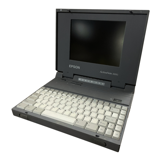
Identifying the System Parts Before getting started, refer to the illuslrations in this section to identify the different parts of your computer. Front View 1-2 Setting Up the Computer... -
Page 18: Setting Up The Computer
LEDS The LEDs (light emitting diodes) on your computer provide information about its operation, as shown in the following table. LED functions Power Low battery Charging Suspend mode Hard disk drive NumLock Caps Lock !krdLock Function lndicates the computer is on: the AC adapter, battery pack. -
Page 19: Rear Panel And Left Side
Rear Panel and Left Side Connecting the AC Adapter The AC adapter is designed to be used in most countries, as it can operate in the ranges 100 to 240 VAC, 50 to 60 Hz (autosensing). Caution Use only the AC adapter (model number AP-3S25) supplied with the computer. - Page 20 You may need to connect the AC adapter to charge the battery before you use it for the first time. (SeeChapter 3 for complete instructions on powering the computer with the AC adapter and/or the battery.) Follow these steps to connect the adapter to the computer: 1.
-
Page 21: Opening The Screen
Opening the Screen To open the LCD samm, place the computer on a level surface. Facing the front of the computer, slide the release latches toward the sides and lift up the screen. Connecting the Trackball Your computer package includes a, trackball, which you connect to the MOUSE port on the left side of the computer. -
Page 22: Attaching The Trackball
Before you can use an optional device like the trackball, you must install special software, called a device driver. The device driver allows the operating system and your application software to recognize the device. The device driver and utilities for the trackball have already been installed on your hard disk so the Action-Note will recognize the trackball as soon as you turn it on. -
Page 23: Turning On The Computer
Follow these steps to attach the trackball to your computer: 1. Press the button on the attaching devics. The clip extends so youcan& clamp the device onto the side of your computer. 2. Clip the attaching device onto either side of the keyboard or screen and release the button. - Page 24 Before you turn on the computer, first connect and turn on any external devices you will be using--such as a printer or monitor. (See Chapter 4 for information about installing optional devices.) Then press the power button on the top of the computer to turn it on..
-
Page 25: Using Your Operating System
When the computer completes its testing, it displays a screen describing the system's configuration. If necessary, press the Pause button on the keyboard to view the configuration screen. Then press any key to continue the startup Process.- Because your-computer was set up at the factory, the configuration information should be accurate. -
Page 26: Chapter 2 Using Your Computer
Chapter 2 Using Your Computer This chapter describes how to use your ActionNote computer on a daily basis. It provides information on the following procedures: Taking care of the computer Backing up your files Using the password function Using the keyboard Reseting the computer Turning off the computer Changing the CPU speed... -
Page 27: Taking Care Of The Computer
Taking Care of the Computer Before you begin using your computer, read the following guidelinesto ensure proper maintenance of the ActionNote: Keep the computer and AC adapter dry, and do not expose them to extreme heat or cold. Do not place external devices on top of the computer, even if it is closed, to prevent damage to the LCD display. -
Page 28: Backing Up Your Files
Backing Up Your Files Be sure to back up your files regularly. For large amounts of data, you might want to consider a portable tape backup unit. Make copies of all your system and applicatioon program diskettes before copying the programs to the hard disk. Your computer comes with video drivers and utilities already installed on the hard disk. -
Page 29: Typing The Password
If you want to change your current password or disable the password function, you need to use the Setup program. See Chapter 5 for instructions. If you forget your password, call the EPSON Connection for assistance at 1-800-922-8911 in the United States or 1-800-GO-EPSON in Canada. 2-4 Using Your Computer... -
Page 30: Using The Keyboard
Using the Keyboard Although the keyboard on the ActionNote has only 84 keys (85 on the international version), its still provides all the functions of a full-size (102-key) keyboard. For example, a full-size keybard has a separate numeric keypad you can use for both numberic entry and cursor control. -
Page 31: Using The Embedded Numeric Keypad
Using the Embedded Numeric Keypad The embedded numeric keypad allows you to enter numeric character from the keyboard when the Num Lock function is on. You can also use the keyboard to control the cursor. The embedded numeric keypad is shown below: Press NumLock to turn Num Lock (and its LED) on and off. -
Page 32: Resetting The Computer
The following table summarizes how to use the embedded numeric keypad. Embedded keypad functions Embedded numeric keys Keys pressed by themselves Keys pressed with Shift Keys pressed with Fn Keys pressed with Shift and Fn Resetting the Computer If necessary, you can clear the computer's current settings or its memory without turning it off by resetting it. -
Page 33: Turning Off The Computer
If you are using MS-DOS, DOS, hold down Ctrl and Alt and press Delete to reset the computer. (If you are in Windows, you must press Ctrl Alt Delete a second time to reset the computer.) The screen goes blank for a moment and then the computer reloads MsDoG. If resetting does not correct the problem, you probably need turn it off and back on a gain. -
Page 34: Adjusting The Lcd Screen
If necessary, press NumLock to turn Num Lock (and its LED) on. Then, to change to low speed, press Ctrl Alt --. To change back to high speed, make sure Num Lock is on, and press Ctrl Alt +. Note You must press -- or + on the embedded numeric keypad only. -
Page 35: Using The Video Utilities And Drivers
To insert a diskette, hold it with the label facing up and the metal shutter leading into the drive. Slide it into the drive until it clicks into place. When you want to is off, then press the release button. When the diskette pops out, remove it and store it properly. - Page 36 The high-resolutian display drivers for Windows 3.1 are installed on your computer. To obtain drivers for non-Windows applications, call the EPSON Connection or access the Epson America Forum on CompuServe. Following is a summary of the video utilities on your system. Note that SetRES, WinPanel, and CLMODE all include extensive on-line help.
- Page 37 CLMODE is a DOS program that provides comprehensive features for configuring your video system. The main functions of CLMODE are Configuration, which offers the same options as WinPANEL; Monitor Type, which allows you to select different external monitor configurations based on refresh rate and resolution;...
-
Page 38: Powering The Computer
C h a p t e r 3 Powering the Computer You can operate your ActionNote using the AC adapter, optional automobile adapter, or the removable battery pack. This chapter describes how to use these power sources, and how to conserve energy when using the battery pack. -
Page 39: Using The Battery Pack
Note Use only the battery packs designed for use with the ActionNote 500 series (A880451 or A881181). Replacing the Battery Pack Follow these steps to install the battery pack: 1. Turn off the computer. - Page 40 4. Press down on the release buttons on the battery compartment cover and slide the cover toward you. Pull up on the cloth tab and lift out the low battery. Remove the fully charged battery pack from its carrying case and slide it into the slot.
-
Page 41: Recharging The Battery
7. Slide the battery cover back into place making sure the tabs on the cover fit into the slots on the computer's cover. Press the cover from the back side until it snaps closed. 8. Turn the computer right side up. Recharging the Battery The battery pack that comes with you ActionNote is rechargeable. -
Page 42: Extending Battery Life
The computer takes approximately 3½ hours to charge a completely discharged battery pack. If you use the system while the battery is recharging, is can take up to 6 hours. If the battery still some charge left when you start charging, the time will be less. -
Page 43: Low Battery Indicator
C a u t i o n When your battery can no longer be recharged, please cannot your local government agency responsible for hazardous waste disposal. NiCad and NiMH batteries are considered hazardous waste and should be recycled or disposed of properly. Low Battery Indicator When the battery's power is getting low, the low battery light starts flashing and the computer starts beeping. -
Page 44: Using The Suspend/Resume Switch
Using the Suspend/Resume Switch The suspend/resume switch provides an efficient way to save battery power. This switch is located on the top left side of the computer. Slide the suspend/resume switch to the right to temporarily stop system activity when you do not need to use your computer for short periods of timt. -
Page 45: Using Setup To Conserve Battery Power
Using Setup to Conserve Battery Power The setup program includes power management options that enable you to conserve battery power. These options allow you to control various functions of computer so you don't waste power on devices you are not using. The power management options are available from the Power Managamnt portion of the setup program. -
Page 46: Connecting Optional Devices
Chapter 4 Connecting Optional Devices This chapter describes how to connect the following optional devices to your ActionNote: External monitor Parallel printer or other device Serial device External keyboard Mouse or other pointing device Telephone line for internal fax/modem. This chapter also describes how to install the following upgrade options: Expansion memory module Numeric coprocessor. -
Page 47: Connecting An External Monitor
Connecting an External Monitor The VIDEO port on your computer allows you to connect an external color or monochrome VGA monitor. When a monitor is connected, you can displayd data on either the LCD screen, the monitor, or both at the same time. You can also display higher-resolution video modes on the external monitor. - Page 48 Connect the monitor cable to the port labelled VIDEO on the back of the computer. If the connector has retaining screws, tighten them by hand or with a screwdriver. Connect the other end of the cable to them monitor, if it is not already attached.
-
Page 49: Using The External Monitor
High resolution display drivers for Microsoft Window 3.1 are already installed and available on your hard disk drive. To obtain drivers for other applications, access the Epson America Forum on CompuServe or call the EPSON Connection at 1-8---922-8911 in the United States or 1-800-GO-EPSON in Canada. -
Page 50: Connecting A Parallel Printer
Connecting a Parallel Printer You can use the PRINTER port to a aparallel device, such as a Centronics -compatible printer. Before connecting a printer, ® check the manual that came with it to see if you need to change any of its settings. Follow these steps to connect a parallel device: 1. -
Page 51: Connecting A Serial Device
5. Connect the other end of the cable to the printer. If the printer interface has retaining clips, squeeze them gently until they snap into place. Connect the printer's power cable to a grounded electrical socket. Connecting a Serial Device You can use the COM1 port to connect a serial device. -
Page 52: Checking The Serial Port Settings
4. Connect the other end of the cable to the serial device. If the connector has retaining screws, tighten them. 5. Connect the serial device's power cable (if it has one) to a grounded electrical socket. Check the documentation that came with your serial device to see if any other steps are necessary. -
Page 53: Connecting An External Keyboard
Connecting an External Keyboard If you are typing for extended periods of time, you may want to connect an external keyboard to the KB on your computer. Although the KB and MOUSE ports look the same, they cannot be used interchangeably. Be sure to plug your keyboard into the KB port to avoid damaging your system. -
Page 54: Connecting The Fax/Modern Telephone Line
The modem will then be ready to use. Note If your computer did not come with the internal fax/modem installed, you must have an Authorized EPSON Servicer install it. If you purchased a fax/modem with your computer, a telephone cable is include in your package. -
Page 55: Adding Memory Modules Or A Numeric Coprocessor
Caution It is best to have your Authorized EPSON Servicer install the memory module or a numeric coprocessor for you because they can be damaged easily if installed incorrectly. If you prefer to install them yourself, carefully follow the instructions in this section. -
Page 56: Removing The Keyboard
Removing the Keyboard To remove the keyboard, follow these steps: 1. Make sure the computer is turned off. 2. Discount all cables from the ports and connectors on both the sides and back of the computer. 3. Turn the computer upside down with the front facing you. 4. - Page 57 Open the top cover. Carefully detach the keyboard by lifting up on the front and sides of the keyboard. Then pull it toward you. Turn the keyboard upside down by tilting the front of the keyboard up and toward the LCD. Carefully set the keyboard on top of the computer.
-
Page 58: Installing A Memory Module
Installing a Memory Module Your computer comes with 4MB or 8MB of memory. Four MB are soldered directly onto the system board. You may have purchased your computer with a 4MB memory module installed. If not, you can increase your memory to 8MB by installing the memory module in the socket shown above. - Page 59 3. Carefully press the module straight into the socket. The connector and socket are designed so they fit together only if you have aIigned them correctly; so do not force them. If you have trouble, remove the module and try again. When the connector is firmly attached to the socket, insert and tighten the screw on the left side of the module.
-
Page 60: Installing A Numeric Coprocessors
Contact the EPSON connection or your sales representative for additional information on choosing a numeric coprocessor compatible with the Cyrix 486SLC2-50 CPU. - Page 61 When you turn on the computer, the system configuration screen shows that a numeric coprocessor is present Caution If you need to remove the yourself. This procedure requires a special extraction tool. Contact your Authorized EPSON Servicer. 4-16 Connecting Optional Devices math coprocessor,...
-
Page 62: Replacing The Keyboard
Replacing the Keyboard After installing a memory module a numeric coprocessor, follow these Steps sbeps to replace the keyboard: 1. Carefully lift the keyboard off the top of the computer,tum it right side up, and align it over the front of the computer. Make sure the keyboard cables are not twisted. - Page 63 Turn the computer upside down with the front facing you and replace the three screws on the front side of the cover. 5. Replace the battery pack. 6. Turn the computer right side up. 7. Connect any optional external devices. 4-18 Connecting Optional Devices...
-
Page 64: Running Setup
Chapter 5 Running Setup The Setup program defines your system’s configuration so the computer uses all of its devices properly. Because your computer If you add optional devices,however,yauneedtonmtheSetup program to update your configuration. The Setup programis staredinthe~ter’sROMBIOS (read-only memory, basic input/output system. Any time you turn on or reset your computer you can run Setup t verify of change the following: Basic settings, such as the current date and time... -
Page 65: Starting The Setup Program
Starting the Setup Program To start the Setup program, you must turn onorresetttre computer. During the startup process, you see the following promp on the screen Pressif you want to run Setup As soon as you see this message, press Delete. If you have already enabled the password function for the Setup program, you will be prompted to enter it now. -
Page 66: Changing The Settings
Changing the Settings At the bottom of each Setup screen, you see a list of the keys you can use to select options on that-screen. Their function described in the following table.(Each screen liststhekeys available; use only the keys listed for that screen.) Setup function keys Key(s) PgUp of PgDn... -
Page 67: Changing The Basic Settings
Changing the Basic Settings when you select Basic Settings from the main menu, you see as screen displaying a calendar and information about your system memory, in addition to the options you can select. The Basic Settings options are described in the following table. -
Page 68: Changing The Custom Settings
changing the Custom Settings When you select see a screen displaying a number of optians you can use to customize the way your system operates. The custom settings options are described in the following table. Custom settings Option Typematic rate delay Typematic rate Fast boot... - Page 69 Custom settings (continued) Option Bootsequence Password Shadow video BIOS CPU cache Non-cocheable Enables or disables a block of memory: block 1 size Non-cacheable block 1 addr Non-cacheable block 2 size Non-cacheable Display the starting address of the second non-cache block2addr 5-6 Running Setup Function Specifies the order in which the checks the...
-
Page 70: Changing Power Management Settings
Changing the Power Management Settings When you select Power Management from the main menu, you see a screen displaying options that you can use to save battery power. These settings configure your system to enter the suspend mode automatically. Press an optian is highlighted,the setup program displays information about the option, including the possible settings. -
Page 71: Changing The Password
Caution If you do set a password, be sure it is easy to remember. If you forget password, you will have to call the Epson Connection for assistance. Follow these steps to set up or change your password: 1. - Page 72 After typing the password, press Enter. You see the following prompt: Re-Enter NEW Type the same password again and press Enter. (This confirms your password for the system.) The program displays the following message: NEW Password Installed 5. Press Esc to return to the main menu screen. Highlight Save Settings and Exit and press Enter.
-
Page 73: Appendix A Troubleshooting
Appendix A Troubleshooting You probably won’t encounter any difficulties as you set up and use your ActionNote. If anything out of the ordinary happens, refer to this appendix for help. It provides the following problem-solving sections: The computer won’t start Battery problems AC adapter problems The LCD screen is blank... -
Page 74: Identifying Your System
Then contact your Authorized FPSON Servicer or call the EPSON Connection at 1-800-922-8911 in the United States or 1-800-GO-EPSON in Canada. Identifying your System... -
Page 75: Error Messages
If the error is serious, the computer cancels further checking and halts system initialization. The error message remains on the screen and the computer locks up. If this happens, contact your Authorized EPSON Servicer as soon as possible to report this information and the error message. The Computer Won't Start... -
Page 76: Battery Problems
Battery Problems If you have trouble minning the computer from the battery pack, follow the steps in this section to find the problem. (Be sure to read Chapter 3 for information on the battery.) 1. Check the low battery light. It is blinking, the battery is low and you need to recharge it. -
Page 77: Ac Adapter Problems
Caution When your battery can no longer be recharged, please contact your local government agency responsible for hazardous waste disposal. NiCad and NiMH batteries are considered hazardous waste and should be recycled or disposed of properly. AC Adapter Problems If the computer does not work properly with the AC adapter, check the power light. -
Page 78: The Lcd Screen Is Blank
The LCD Screen is Blank If the computer starts up but no image appears on the LCD screen, follow these steps to solve the problem: 1. Use the brightness and contrast controls to adjust the screen display. To save power, you may have set a timeout period for the LCD screen in the Setup program or with the WinPANEL utility. -
Page 79: The Computer Locks Up
If the outlet works and an image still does not appear on your monitor when you turn on the computer, contact your Authorized EPSON Servicer. The Computer Lock Up If the computer locks up and does not respond to your keyboard entries, try the following: Wait a few minutes to see if the computer really is disabled. -
Page 80: Password Problems
2 . If you know the current password but you want to change it, see Chapter 5 for instructions. 3. If you have forgotten your password, call the EPSON Connection for assistance at 1-800-922-8911 in United States or 1-800-GO-EPSON in Canada. -
Page 81: Diskette Problems
Diskette Problems If you have trouble accessing data on a disckette, follow steps to identify the problem: 1 . Is the diskette properly inserted in the drive? Remove the diskette from the drive and make sure it is inserted with the label facing up. -
Page 82: Diskette Drive Problems
If the light is blinking, there may be a problem with the hard disk. Contact your Authorized EPSON Servicer if this occurs. 2. If you have set a timeout for the hard disk in the Setup... -
Page 83: Software Problems
Software Problems If you are having trouble with an applicaton program, try the following solutions: If the application program does not start, check that you are following the correct procedure for starting the program, and that it is installed correctly. If the program is stored in a directory on the hard disk drive, make sure you are working in or specifying the corrct directory. -
Page 84: Printer Problems
Printer Problems You can solve most printer problems by followinjg the instructions in your printer manual. If you have just connectedthe printer, first check that the pritner has power and is correctly connected to the computer. See Chapter 4 for instructions on connecting a printer. (The printer manual also gives instructions on cable connections.) If you have a serial printer or if you have problems feeding paper, check the printer manual for the correct DIP switch settings. -
Page 85: Trackball Or Pointing Device Problems
2. Check whether the LEDs on the keyboard light up when you turn on the computer. 3. If you think there is something wrong with the keyboard, consult the dealer from whom you purchased it, or call the EPSON Connection for assistance. Troubleshooting A-13... -
Page 86: Numeric Coprocessor Problems
If you have installed a numeric coprocessor but it doesn't seem to be operating properly, check the documentation that came with it for troubleshooting information and for any diagnostic procedures you can perform. Contact your Authorized EPSON Servicer or call the EPSON Connection if you cannot solve the problem. Caution Do not attempt to remove the numeric coprocessor yourself;... -
Page 87: Appendix B Fax/Modem
See the BitCom and WinFax LITE software manuals for more information about how to use them. Note If your computer did not come with an internal fax/modem, and you purchased one later, you must have an Authorized EPSON Servicer install it for you. Fax/Modem B-1... - Page 88 The following table provides specifications for the fax/modems that may be installed in your ActionNote computer: Specifications Compatibility Speed (baud) Command set Error correction Data compression Dialing Serial port B-2 Fax/Modem 9600 fax/2400 modem Modem Bell 103, Group 3, 212A, Class 2, CCITT G3, CCITT V.21,...
-
Page 89: Built-In Command Set
Built-in Command Set If you are not using a telecommunications program, you can use the fax/modem’s built-in command set. These commands are compatible with the Hayes Note When you use a telecommunications software program like BitCom or WinFax LITE, it provides its own set of commands that control the fax/modem. -
Page 90: At Command Summary
AT Command Summary Command Sr=n Fax/Modem B - 4 Description Escape code Repeat last command string Attention Answer immediate (incoming call) CCITT v.22 protocol at 1200 bps Bell 103/212A protocol at 1200 bps Dial: originates a call Echo off (command mode) Echo on (command mode) On hook: hang up immediately Off hook: ready to dial... - Page 91 AT Command Summary (continued) Command Description Enables all result codes Disable long space disconnect Enable long space disconnect Software reset; recalls user configuration 0 Software reset; recalls user configuration 1 &C0 DCD signal always on &C1 DCD signal on when carrier present &D0 Ignore DTR signal &D1...
-
Page 92: Dial Modifiers
Dial Modifiers Modifier Command Summary Command \ A 0 \ A 1 \ A 2 \ G 0 \ J 0 \ N 0 Fax/Modem Description Hookflash (0.5 seconds) Pause (2 seconds) Return to command state after dialing Wait for 5 seconds if silent answer Pulse dialing Reverse to answer mode Dial stored number... - Page 93 MNP Command Summary (continued) Command Description \ N 2 Set reliable mode \ N 3 Set auto-reliable mode Set V.42(LAP-M) mode Set V.42 auto-reliable mode \ N 5 Set V.42/MNP reliable mode \ N 6 \ N 7 Set V.42/MNP auto-reliable mode Force a reliable link independent of whether or not the modem originated or answered the call Disable flow control...
- Page 94 Command Summary (continued) Command &Q6 &Y0 &Y1 %A n -C n Register Summary Command Description Auto-answer ring number Ring counter Escape code character Carriage return character Linefeed character Backspace character Wait time, dialing Wait time, before carrier Dial pause duration Carrier response Carrier loss disconnect Tone duration and spacing...
-
Page 95: At Register Summary
AT Register Summary (continued) Command Description Reserved Option register (see below) Reserved Self-test register Reserved Self-test timer value Reserved Reserved Option register (see below) Option register (see below) Option register (see below) Reserved DTR delay value RTS to CTS turnaround delay Option register (see below) MNP modem line connect... -
Page 96: Option Registers
Option Register S14 Bit mapped configuration register Bit 0 Unused Bit 1 Bit 2 Bit 3 Bit 4 Unused Bit 5 Bit 6 Unused Bit 7 S21 Bit mapped configuration register Bit 012 Unused Bit 34 Bit 5 Bit 6 Unused Bit 7 B-10 Fax/Modem... - Page 97 S22 Bit mapped configuration register Speaker volume low (L0) Bit 01 Speaker volume low (L1) Speaker volume medium (default L2) Speaker volume high (L3) Bit 23 Speaker disabled (M0) Speaker on until carrier detected (default M1) Speaker always on (M2) Speaker on until carrier detected but off during dialing (M3) Select basic result code set (X0) Bit 456...
-
Page 98: Mnp Register Summary
S27 Bit mapped configuration register Bit 012345 Unused Bit 6 Bit 7 Unused MNP Register Summary S36 Negotiate failure treatment Hang up Attempt direct connection Reserved Attempt normal connection Attempt V.42bis then MNP 5 connection, if fail, hang up 5 or 7 Attempt V.42bis then V.42, then MNP 5 connection, if fail, negotiate MNP 2-4 with constant terminal speed S46 Protocol selection... -
Page 99: Result Code Summary
Result Code Summary Word CONNECT RING NO CARRIER ERROR CONNECT 1200 NO DIAL TONE BUSY NO ANSWER CONNECT 2400 CONNECT 1200/REL 4 CONNECT 1200/rel 5 CONNECT 2400/REL 4 CONNECT 2400/REL 5 CONNECT 1200/v.42 CONNECT 2400/v.42 Number Description Command executed Connect at 300 bps Telephone is ringing Carrier lost or not detected Command entry error... -
Page 100: Appendix C Specifications
Appendix C Specifications This appendix lists the specifications for your ActionNote. It also includes the specifications for international power cables. Main Unit system memory ROM BIOS Numeric coprocessor Clock/ calendar Video RAM Cyrix 486SLC2-50 microprocessor 4MB or 8MB; expandable to 8MB; the first 64OKB is conventional memory and 128KB is used for shadow RAM;... -
Page 101: Controllers And Connectors
Controllers and Connectors Diskette drive Hard disk External video Parallel Serial Pointing device External keyboard Speaker Modem Phone jock C-2 Specifications Built-in controller for one internal 3½-inch diskette drive; supports 1.44MB and 720KB formats Built-in controller for internal hard disk drive Built-in 16-bit local bus video controller supporting maximum resolution of 640 x 480, 256 colors... -
Page 102: Input Devices
Input Devices Keyboard Trackball Storage Mass Diskette drive Hard disk drive Display Color LCD Power Supply AC adapter Battery pack 84/85 (US) keys; embedded numeric keypad and F11 and F12 keys Portable trackball with drivers and utilities installed One internal, 3.5 inch diskette drive; 1.44MB and 720KB formats One internal hard disk drive;... -
Page 103: Physical Dimensions
Caution Use only the AC adapter, optional automobile adapter, and battery designed for use with the ActionNote (AC adapter model number AP-3S25, battery model number A880451 and NiMH batter model number A881181). Physical Dimensions Height Width Depth Weight Environmental Requirements Temperature Humidity Acoustical Noise... -
Page 104: Power Source Requirements
Power Source Requirements 120 volt power source requirements AC plug 240 volt power source requirements AC plug Reference Plug type standards North America ANSI C73.11 125v. 10A NEMA 5-15-P IEC 83 Reference Plug type standards Europe CEE 7/7 240V. 10A to IEC 83 IEC 127 HD 21... -
Page 105: Glossary
G l o s s a r y 486SLC2-50 A clock-doubled CPU specifically designed for high-performance, low-power systems. The chip is fully compatible with the 486 instruction set, and includes a 1KB instruction/data cache. The CPU core operates at 50 MHz-twice the speed of the system. AC adapter The device that converts AC voltage from a wall outlet into the proper DC voltage to power your Action Note. -
Page 106: Cpu Speed
COM1 The name that MS-DOS uses to identify the primary serial port. CONFlG.SYS file A special system file that MS-DOS executes each time you turn on or reset the computer. You use this file to customize your system by installing device drivers, setting limits for files and buffers, and Specifying Ms-DOS commands to be run during startup. -
Page 107: Embedded Numeric Keypad
Cathode Ray Tube A type of video display, such as a color monitor or a TV screen. Device Driver A program that controls a specific piece of equipment in the system Examples of drivers include expanded memory managers, display drivers, printer and mouse drivers. Embedded numeric keypad See Numeric keypad. -
Page 108: Math Coprocessor
Light Emmitting Diode. An indicator light such as those used for the Action Note power, disk drives, and keyboard settings. Local bus An internal group of wires that sends information from the microprocessor to the video controller in the ActionNote. Local bus video provides increased performance. -
Page 109: Numeric Keypad
Nicad Nickel cadmium. A type of battery used in the ActionNote 5OO series. NiMH Nickel-metal-hydride A type of battery used in the Action Note 500 series. Numeric coprocessor See Coprocessor. Numeric Keypad The embedded numeric keypad in the Action Note keyboard, which You can activate either by turning on the Num Lock function or by holding down the Fn and Shift keys. - Page 110 Power-on diagnostics A set of testing routines the computer performs automatically every time you turn it on. R A M Random Access Memory. The portion of the computer's memory that runs programs and temporarily stores data while you work. All data stored in RAM is temporarily maintained while the computer is in Suspend mode, but erased when you turn off the computer.
-
Page 111: Suspend Mode
S e r i a l A way of organizing communications between communications between two pieces of computer equipment, in which the signals that make up cash character are sequnuentially.See alsoParullel. Setup The program you run to define the configuration settings and Power Management options of your computer. -
Page 112: Index
Index AC adapter Connecting, 1-4-5 Part numbers, C-4 problems, A-5 recharging battery, 3-4 u s i n g , 3 - 1 AC plugs, C-5 Acoustical noise, C-4 Adapter, automobile cigarette lighter, Intro-3, 3-1 Altitude, C-4 Application programs problems, A-11 video drivers, 2-11, 4-4 A T c o m m a n d s u m m a r y , B - 4 - 5 AT register summary, B-8-9... - Page 113 2 Index Display external monitor, 2-10-12, 4-4 LCD, 2-l0-12, 4-4 specifications, c-3 Disposal, battery pack(s), 3-6 Drivers, video, 2-3, 2-11 Embedded numeric keypad 2-6-7 EPSON Connection Intro-4 Error correction, B-2 Error messages, power-on diagnostic, A-3 -External keyboard connecting, 4-8 controller, C-2...
- Page 114 Fax/modem data compression, B-2 dial modifiers, B-6 error correction B-2 issuing commands, B-3 MNP command summary, B-6-8 MNP register summary, B-12 on-line state, B-3 option registers, B-10 result code summary, B-13 specifications, B-2 WinFax LlTE software, Intro-2, 4-10, B-1 Fn key, 2-5--6 Hard disk drive controller, C-2 LED, 1-3...
- Page 115 problems, A-13 MS-DOS keyboard layouts, 2-5 operating system, 1-10 VERcommmd,A-2 version number, A-2 pack NiCad, NiMH battery see Battery pack(s) Num Lock function, 2-6 Num Lock LED, 1-3 Numeric coprocessor adding, 4-10-12 installing, 4-15-16 problems, A-14 removing, 4-16 specifications, C-l Numeric keypad, 2-6-7 on-line slate, fax/modem, B3 On-line support, CompuServce,...
- Page 116 RAM, Intro-1, 4-13, A-3, C-1 Read-only memory (ROM), 5-1, A-3 Recharging battery, 3-4-5 Removing diskettes, 2-10 keyboard, 4-11-12 Replacing battery pack, 3-2--4 keyboard, 4-17-18 Resetting computer, 2-7 Resolutions, video, Intro-1, 2-10-12, 4-4, C-2 Result code summary, B-13 ROM, 5-1, A-3 ROM BIOS, 5-1, A-2, C-1 Safety instructions, iii-iv Saving battery power, 3-7-8, 5-7...
- Page 117 Timeout periods, 5-7-8 Trackball attaching, 1-7 connecting, 1-6-7 problems, A-13 specifications, C-3 Troubleshooting A-1-14 Tuning off compukr, 2-8 Tuming on computer, 1-8-9 militias, video, 2-3,2-10-12 monitor, 4-2 resolutions, Intro-1, 2-10-12 4-4, Video controller, Intro-1, C-2 modes, 2-12 utilities and drivers, 2-3, 2-10-l2 VIDEOport,1-1 ,4-2-3 Video RAM, C-1 Windows, 1-10, 2-11...
- Page 118 Epson America (USA) Epson America, Inc. 20770 Madrona Avenue Torrance, CA 90509-2842 Tel: (310) 782-0770 (800) 289-3776 Fax: (310) 782-5051 Epson Direct P.O. Box 2858 20770 Madrona Avenue Torrance, CA 90509-1111 Tel: (800)374-7300 Epson America (International)
-
Page 119: Epson International Marketing Locations
Epson International Marketing locations...