
Related Manuals for Emerson Liebert CW


Summary of Contents for Emerson Liebert CW
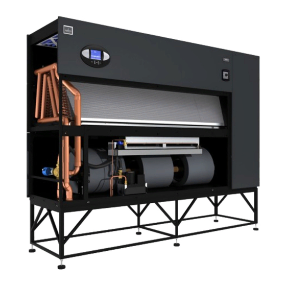
- Page 1 Liebert ® ™ System Design Manual - 26-181kW, 50 & 60Hz Precision Cooling For Business-Critical Continuity™...
-
Page 3: Table Of Contents
CW M IEBERT ODEL UMBER CW P IEBERT ERFORMANCE CW P IEBERT ERFORMANCE —U LECTRICAL CW106 and CW114 Electrical Data with EC Fans ....... . . 5 CW181 Electrical Data with EC Fans. -
Page 5: Liebert Cw Model Number Nomenclature
CW M IEBERT ODEL UMBER CW = Liebert CW D = Downflow Floor Mount U = Upflow Chilled Water Unit Nominal Capacity, kW OMENCLATURE C = Chilled Water A = 460/3/60 B = 575/3/60 C = 208/3/60 D = 230/3/60... -
Page 6: Liebert Cw Performance Data -50 & 60 H Zsystems
Press. Drop - ft (kPa) 31.6 (94.3) 43.4 (129.5) 31.8 (94.9) 22.3 (66.5) 18.7 (55.8) 23.4 (69.8) 39.3 (117.3) 42.8 (127.7) 66.6 (198.7) Unit capacity data is “net,” and is certified to ASHRAE 127-2007 rating standard Liebert CW Performance Data—50 & 60 Hz Systems —50 & 60 H... - Page 7 CONNECTION SIZES Chilled Water-OD Copper 1-1/8 Infrared Humidifier-OD Copper Condensate Drain-FPT Steam Reheat-MPT Hot Water Reheat-OD Copper Steam Humidifier-MPT Weight-lb (kg)- Installed 810 (367) Liebert CW Performance Data—50 & 60 Hz Systems CW038 CW041 CW051 CW060 6050 5900 9300 9100 (10,280)
-
Page 8: Liebert Cw Performance Data-Models With Ec Fans, 50 & 60 Hz
Chilled Water-O.D. Copper Infrared Humidifier-O.D. Copper Condensate Drain-FPT Weight-lb (kg)- Installed * Unit capacity data is “net,” and is certified to ASHRAE 127-2007 rating standard Liebert CW Performance Data—Models with EC Fans, 50 & 60 Hz —M ODELS WITH CW106D 435 (127.5) 552 (161.7) -
Page 9: Electrical Data -Units With Ec Fans
—U LECTRICAL CW106 and CW114 Electrical Data with EC Fans Table 1 Electrical data—60Hz-3 phase Reheat Humidifier Electric Infrared Electric Infrared Electric Infrared Electric Infrared None Infrared None Infrared None None None None Table 2 Electrical data—50Hz-3 phase Reheat Humidifier Electric Electric Electric... -
Page 10: Dimensional Data
IMENSIONAL Figure 1 Dimensions, CW026 - CW084 Projection of Display Bezel 3/4" (19mm) 2" (50.8mm) 72" (1829mm) Shaded areas indicate a recommended clearance of 36" (914mm) for component access and filter removal. (25.4mm) 3" (76.2mm) 9" (228mm) 1" (25.4mm) Standard Piping and Electrical Opening Floor Cutout Dimensions Model... -
Page 11: Figure 2 Dimensional Data-50 & 60 Hz Systems Cw106-Cw114, Downflow Models
Figure 2 Dimensional Data—50 & 60 Hz Systems CW106—CW114, downflow models Overall Dimension Projection of Display Bezel 3/4" (19mm) 2" (50.8mm) 76" (1930mm) Shaded area indicates a recommended clearance of 36" (914mm) for component access and filter removal UNIT DIMENSIONAL DATA 20"... -
Page 12: Figure 3 Cabinet And Floor Planning Dimensional Data, Downflow Model Cw181 With Ec Fans
Figure 3 Cabinet and Floor Planning Dimensional Data, Downflow Model CW181 with EC Fans 118" (2997mm) Opening TOP VIEW (3099mm) 76" (1930mm) (3048mm) 1-1/2" FRONT VIEW (38mm) Note: Electrical connections can be made from the bottom of the unit. 39-1/2" (1003mm) Opening 3/4"... -
Page 13: Figure 4 Cabinet And Floor Planning Dimensions, Upflow Models-Cw026-Cw084
Figure 4 Cabinet and floor planning dimensions, upflow models—CW026-CW084 Projection Of Display Bezel 3/4" (19mm) 1" (25.4mm) 72" (1829mm) Air grille may be supplied on units with front or rear return air Shaded areas indicate a recommended clearance of 36" (914mm) for component access and filter removal. -
Page 14: Figure 5 Cabinet And Floor Planning Dimensions, Cw 106 And Cw114 Upflow Models
Figure 5 Cabinet and floor planning dimensions, CW 106 and CW114 upflow models 35" Overall (889mm) Projection of Display 32" Bezel 3/4" (19mm) (813mm) Plenum 2" (51mm) Flange 76" (1930mm) Air grille supplied on units with front return air only Shaded areas indicate a recommended clearance of 36"... -
Page 15: Upflow Duct
PFLOW ONNECTION Model No. No. of Chilled Blowers Water CW026 15-7/8 (403) 18-5/8 (473) 2-3/16 (55) 17-7/8 (454) CW038 15-7/8 (403) 18-5/8 (473) 2-3/16 (55) 17-7/8 (454) CW041 15-7/8 (403) 18-5/8 (473) 2-3/16 (55) 17-7/8 (454) CW051 15-7/8 (403) 14-5/8 (371) 2-3/16 (55) 20-3/8 (517) 11-1/4 (288) 74 (1880) 35 (889) 68 (1727) 20 (508) CW060 15-7/8 (403) 14-5/8 (371) 2-3/16 (55) 20-3/8 (517) 11-1/4 (288) 74 (1880) 35 (889) 68 (1727) 20 (508) CW076... -
Page 16: Blower Duct
& D LOWER Model Blower Supply Top Front CW106 15 x 15 Top Rear Top Front CW114 15 x 11 Top Rear Flanges Provided on Blower Outlets for Supply Air Ducting TOP-FRONT SUPPLY SHOWN Filter Access (both ends) 4" (102mm) (57mm) 122"... -
Page 17: Electrical
LECTRICAL PECIFICATIONS Table 5 Electrical data—50 Hz systems Reheat Options Humidifier Options Models Motor HP Volts 46.7 CW026 49.8 62.9 CW038 68.6 62.9 CW041 68.6 94.6 CW051 103.9 107.9 101.4 CW060 117.2 109.5 126.6 122.6 CW076 10.0 131.7 128.4 126.6 122.6 CW084 10.0 131.7 128.4... -
Page 18: Table 7 Electrical Data-60 Hz Systems
Table 7 Electrical data—60 Hz Systems Chilled Water Models - 60Hz Reheat Options Electric Infrared or Steam Humidifier Options Generating Models / Motor Volts 208 48.6 44.1 CW026 60.8 55.1 2.0 HP MFCB 51.7 46.9 CW026 64.6 58.6 3.0 HP MFCB 65.5 59.8... -
Page 19: Table 8 Indoor Evaporator Fan Motor Electrical Requirements-60Hz Systems
Table 7 Electrical data—60 Hz Systems (continued) Chilled Water Models - 60Hz Reheat Options Electric Infrared or Steam Humidifier Options Generating Models / Motor Volts 208 165.1 154.8 77.7 CW106 20.0 HP WSA 206.4 193.5 97.1 (Upflow only) MFCB 225 136.5 128.8 64.7 CW114 WSA 170.6 161.0 80.9... - Page 20 UIDE PECIFICATIONS ENERAL Summary These specifications describe requirements for a precision environmental control system. The system shall be designed to maintain temperature conditions in the rooms containing electronic equipment. The manufacturer shall design and furnish all equipment to be fully compatible with heat dissipation requirements of the room.
-
Page 21: Guide Specifications
System Auto Restart - The auto restart feature will automatically restart the system after a power failure. Time delay is programmable. Sequential Load Activation - On initial startup or restart after power failure, each operational load is sequenced with a minimum of one second delay to minimize total inrush current. Hot Water Flush Cycles - Hot water reheat coils and Econ-O-Coils are periodically flushed to pre- vent a buildup of contaminants. - Page 22 The Service Menus Shall be Defined as Follows Setpoints: Menu shall allow setpoints within the following ranges: • Temperature Setpoint 65-85ºF (18-29ºC)* • Temperature Sensitivity +1-10ºF (0.6-5.6ºC) • Humidity Setpoint 20-80% RH* • Humidity Sensitivity 1-30% RH • High Temperature Alarm 35-90ºF (2-32ºC) •...
-
Page 23: Table
Advanced Menus Factory Settings: Configuration settings shall be factory-set based on the pre-defined component operation. Change Passwords: Menu shall allow new passwords to be set or changed. 2.4.1 Liebert iCOM Microprocessor Control With Large Graphic Display (Optional) The Liebert iCOM unit control with large graphic display shall include all of the features as the Lie- bert iCOM with small graphic display, except that it includes a larger graphical display and shall include the additional features of: “System View”, Spare Parts List, Unit Diary. - Page 24 2.5.1.4 Alarms The Liebert iCOM control shall activate an audible and visual alarm in event of any of the following conditions: • High Temperature • Low Temperature • High Humidity • Low Humidity • Main Fan Overload (opt) • Change Filters •...
-
Page 25: Optional Components
High Pressure Chilled Water Control Valve—Optional The chilled water circuit shall include a 3-way (2-way) high pressure modulating valve. The valve shall be designed for up to 400 PSI (2758 kPa) water pressure. A-Frame Chilled Water Coil The cooling coil shall be of A-frame design with a minimum of ____ sq. ft. (sq.m.) face area, ____ rows deep. - Page 26 2.11.6.3 Liebert SiteScan Site Monitoring System Provide a Liebert SiteScan monitor system with the Liebert CW. The Liebert SiteScan shall have the capability to monitor and change (at the user direction) the temperature setpoints and sensitivities of each unit. The printer shall provide the user with chronological alarm information. It shall also be capable of being programmed to print out environmental conditions or operating modes at each unit.
- Page 28 Embedded Computing Connectivity Embedded Power DC Power Monitoring Business-Critical Continuity, Emerson Network Power and the Emerson Network Power logo are trademarks and service marks of Emerson Electric Co. ©2008 Emerson Electric Co. Technical Support / Service [email protected] Outside the US: 614-841-6755 [email protected]...