Electrolux thermaline S90 Installation And Operating Instructions Manual
Gas heated char grill
Hide thumbs
Also See for thermaline S90:
- Installation and operating instructions manual (66 pages) ,
- Specifications (8 pages) ,
- Install and operation instructions (22 pages)
Available languages
Available languages
Quick Links
See also:
Install and Operation Instructions
GAS HEATED CHAR GRILL - GRILLOIR A GAZ
US
INSTALLATION- AND OPERATING INSTRUCTIONS
FR
INSTRUCTIONS D'INSTALLATION ET D'EMPLOI
FOR YOUR SAFETY
Do not store or use gasoline or
other flammable vapors or liquids
in the vicinity of this or any other
appliance.
WARNING
Improper installation, adjust-
ment, alteration, service or
maintenance can cause property
damage, injury or death. Read the
installation, operating and
maintenance instructions thorou-
ghly before installing or servicing
this equipment.
INSTRUCTION
Post in a prominent location instructions to be followed if the user smells gas. Consult
the local gas supplier to obtain the information.
Présentez dans des instructions en avant d'un endroit d'être suivi si l'utilisateur sent le
gaz. Consultez le fournisseur local de gaz pour obtenir l'information.
thermaline S90
POUR VOTRE SÉCURITÉ
Ne déposez pas ou n'employez
pas l'essence ou d'autres vapeurs
ou liquides inflammables à pro-
ximité de ceci ou d'aucun autre
appareil.
AVERTISSEMENT
L'installation inexacte, l'ajuste-
ment, le changement, le service
ou l'entretien peuvent causer des
blessures matériels, des domma-
ges ou la mort. Lisez les instruc-
tions d'installation, d'opération et
d'entretien complètement avant
d'installer ou entretenir cet
équipement.
Doc.
62.9678.01_UL
Edition 1
02.2006
page 3
page 11

Related Manuals for Electrolux thermaline S90


Summary of Contents for Electrolux thermaline S90
- Page 1 Présentez dans des instructions en avant d'un endroit d'être suivi si l'utilisateur sent le gaz. Consultez le fournisseur local de gaz pour obtenir l'information. thermaline S90 POUR VOTRE SÉCURITÉ Ne déposez pas ou n'employez pas l'essence ou d'autres vapeurs ou liquides inflammables à...
- Page 2 Against wall - contre une paroi Free standing - isolé Connections - Raccordement Gas - Gaz Fig.1 INSTALLATION DRAWINGS - PLANS D'INSTALLATION Doc. 62.9678.01_UL...
-
Page 3: Table Of Contents
CONTENTS GENERAL INFORMATION ... 3 INSTALLATION INSTRUCTIONS ... 5 III. OPERATING INSTRUCTIONS ... 9 SOMMAIRE INSTRUCTIONS GÉNÉRALES ... 11 INSTRUCTIONS RELATIVES À L'INSTALLATION ... 13 INSTRUCTIONS DE FONCTIONNEMENT ... 17 APPENDIX VII. Table of nozzle - Tableau de gigleur 62.9678.01_UL Page 1... - Page 4 Page 2 62.9678.01_UL...
-
Page 5: General Information
GENERAL INFORMATION INSTRUCTIONS FOR SAFETY AND USE INSTALLATION AND INITIAL OPERATION The installation, adjustment and initial opera- tion of the appliance must be carried out according to the manufacturer's instructions and may only be done by an authorised spe- cialist. Installations for the supply of electricity and gas must be carried out by approved special- ists in compliance with specific national and... - Page 6 TECHNICAL DATA Width Depth PNC Appliances Appliance type Height inch 9CHG584089 WDGRAFOOOO 19.7 35.4 9CHG584090 WDGRAAOOOO 35.4 9CHG584091 WDGUAFOOOO 31.5 35.4 9CHG584092 WDGUAAOOOO 35.4 PACKAGING All the packaging materials used are environmentally friendly. They may burnt at an incineration plant or sent for recycling. TESTS / CERTIFICATES All gas appliances are tested according to the standard ANSI Z83.11-2002 and CSA 1.8-2002 of Gas Food Service Equip-...
-
Page 7: Installation Instructions
II . INSTALLATION INSTRUCTIONS INSTALLATION The appliance is designed for connection to fixed lines. The appliances are suitable for setting up as single appliances or as a group of appliances. They can be set up freely in the room, side by side, at the side and/or at the back against a wall. Gaps between two appliances or appliance and sidewall should be filled with a FDA approved silicone such as Samco RTV103. - Page 8 SIDEWALL (D) Fig.2 Assemblage of sidewall The assembly kit contains two of each of the following: hexagonal screws M8x25 (1 / Fig.1), bolts with retaining rings (2 / Fig.1), mounting links (3 / Fig.1), hexagonal screws M8x16 with serrated washers and hexagonal nuts M8, hexagonal screws M5 with serrated washers (4 / Fig.2) and a fastening angle (5 / Fig.2).
- Page 9 FRONT PANELS (A) and (B) Fig.6 Front panel Unscrew screws (1 or 3). Also, in the case of a built-in oven, unscrew screws (2 and/or 4) on the inside of the oven. Pull the panel away forwards and downwards. CONTROL PANAEL (C) (3c) Fig.
- Page 10 Compulsory measures: pressure adjustment by the gas works or con- version of the range by the service personnel. Please refer to "Conversion to another gas type". Gas pressure tolerances...
-
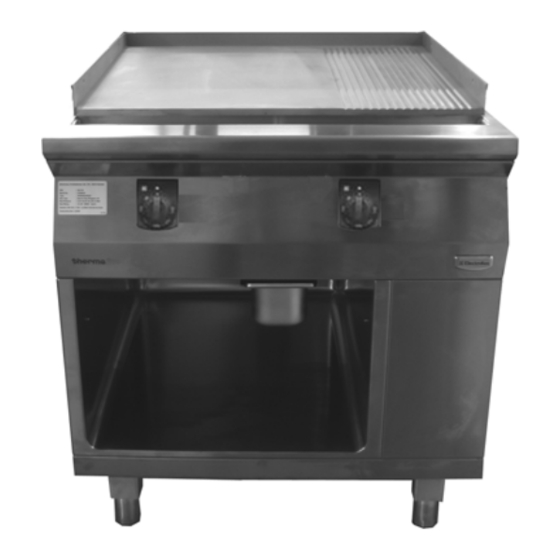
Page 11: Operating Instructions
III . OPERATING INSTRUCTIONS GENERAL The appliance is used for grilling and frying various types of meat, sausages, fish and vegetables. The food to be cooked is placed directly on a grill. Under the grill there are several bar burners, protected from pollution by roof-shaped steel sheets. A removable lateral splashguard protects the surroundings. - Page 12 CLEANING The appliance should be cooled before every cleaning operation. Shut off all the gas taps and control valves on the range. Remove grills, burner covers and splashguard from the appliance for cleaning. Use a brush to wash the grills with hot water to which a fat- dissolving agent has been added, rinse with hot water and rub dry.
-
Page 13: Instructions Générales
INSTRUCTIONS GÉNÉRALES CONSIGNES DE SÉCURITÉ ET D'UTILISATION INSTALLATION ET MISE EN SERVICE Le montage, le réglage et la première mise en service de l'appareil doivent s'effectuer conformément aux instructions du fabricant et être confiés exclusivement à un technicien agréé. Les raccordements au réseau électrique et de distribution du gaz doivent être réalisés par du personnel agréé, dans le respect des dispositions locales en vigueur dans le pays... - Page 14 SERVICE-APRÈS-VENTE ET RÉPARATION Si un problème persistant empêche le fonctionnement correct de l'appareil, mettez- le hors tension et débranchez-le. Pour toute opération d'entretien ou de répa- ration, adressez-vous au fabricant, à un représentant agréé ou au Service Après- vente local. Toute opération de réparation, d'entretien et de réglage doit être effectuée par un techni- cien agréé, en respectant les dispositions...
-
Page 15: Instructions Relatives À L'installation
INSTRUCTIONS RELATIVES À L'INSTALLATION II . INSTRUCTIONS RELATIVES À L'INSTALLATION MISE EN PLACE Cet appareil est conçu pour être raccordé à des conduites fixes. Les appareils peuvent être montés individuellement ou en groupe. Ils peuvent être installés de façon indépendante, côte à... - Page 16 INSTRUCTIONS RELATIVES À L'INSTALLATION PAROI LATERALE (D) Fig.2 Montage du paroi latérale Chaque kit d'assemblage comprend respectivement deux vis hexagonales M8 x 25 (1 / Fig.1), des boulons avec circlip (2 / Fig.1), des éclisses (3 / Fig.1), des vis hexagonales M8 x 16 avec rondelles à...
- Page 17 INSTRUCTIONS RELATIVES À L'INSTALLATION PANNEAU AVANT (A) et (B) Fig.6 Frontblenden Desserrez les vis (1 et 3 Fig.6, Fig.6). Si le four est encastré, desserrez Extrayez le panneau vers l'avant et le bas. PANNEAU DE COMMANDE (C) (3c) Fig.7 Panneau de commande Enlever l'interrupteur rotatif.
- Page 18 INSTRUCTIONS RELATIVES À L'INSTALLATION RACCORDEMENT AU GAZ Le raccordement au gaz, de même que la pose de la conduite d'arrivée de gaz doivent être réalisés exclusivement par un spécialiste agréé, dans le respect des dispositions nationales et locales en vigueur. INSTRUCTIONS •...
-
Page 19: Instructions De Fonctionnement
INSTRUCTIONS DE FONCTIONNEMENT III . INSTRUCTIONS DE FONCTIONNEMENT GÉNÉRALITÉS Cet appareil est destiné à griller et à rôtir différents types de viande, de la saucisse, du poisson et des légumes. Les aliments à cuire doivent être directement posés sur une grille. Sous la grille se trouvent plusieurs brûleurs gaz, protégés contre la pollution par des petits toits en tôle d'acier. - Page 20 INSTRUCTIONS DE FONCTIONNEMENT 2.5.3 MISE HORS SERVICE Lorsque l'appareil est mis hors service pendant une longue période, il convient d'observer ce qui suit : Fermez le robinet à gaz principal (1 / Fig. 9). En cas d'utilisation de gaz liquide, fermez également la valve de la bouteille ou du réservoir à...
- Page 21 INSTRUCTIONS DE FONCTIONNEMENT Espace de rangement L'espace de rangement (Fig.10) est installé dans la partie inférieure de l'appareil. Accessoires conseillés : - Porte-tablette (1) 2 pces. - Tablette (2) 1 pce. 1 Porte-tablette 2 Tablette Fig.10 Espace de rangement 62.9678.01_UL Page 19...
- Page 22 INSTRUCTIONS DE FONCTIONNEMENT Page 20 62.9678.01_UL...
- Page 23 21 Natural 17.4 gas USA 25 Propane 11.0 27.4 10.0 gas USA thermaline S90 Chargrill (12 kW) Category Main flame mbar 0.104 2.65 72.7801.32 0.079 2,00 62.8510.01 0.014 0.35 0.071 1.80 72.7801.05 0.055 1.40 62.8510.02 0.0078 0.20 Small flame Ignitions burner 712 345056.02...
- Page 24 21 Natural 17.4 gas USA 25 Propane 11.0 27.4 10.0 gas USA thermaline S90 Chargrill (24 kW) Category Main flame mbar 0.104 2.65 72.7801.32 0.079 2,00 62.8510.01 0.016 0.071 1.80 72.7801.05 0.055 1.40 62.8510.02 0.0098 0.25 Small flame Ignitions burner 712 345056.05...