Table of Contents
- ELECTRICS HEATED STEAM CONVECTION OVENS
USA
INSTALLATION, OPERATION AND MAINTENANCE
- FORNI CONVEZIONE/VAPORE ELETTRICI
IT
INSTALLAZIONE, USO E MANUTENZIONE
- FOURS A CONVECTION VAPEUR ELECTRIQUES
CDN
INSTALLATION, UTILISATION ET ENTRETIEN
- HORNOS DE CONVECCIÓN Y VAPOR ELECTRICOS
ES
INSTALACIÓN, USO Y MANTENIMIENTO
From the Electrolux Group
Page
Pagina
Page
Pág.
5938 035 01
DOC. NO.
EDITION 1
E-Z-A
9
31
53
75
0802 LA-LC
Table of Contents

Related Manuals for Electrolux 2604


Summary of Contents for Electrolux 2604
- Page 1 - FORNI CONVEZIONE/VAPORE ELETTRICI INSTALLAZIONE, USO E MANUTENZIONE - FOURS A CONVECTION VAPEUR ELECTRIQUES INSTALLATION, UTILISATION ET ENTRETIEN - HORNOS DE CONVECCIÓN Y VAPOR ELECTRICOS INSTALACIÓN, USO Y MANTENIMIENTO From the Electrolux Group Page Pagina Page Pág. 5938 035 01 DOC.
-
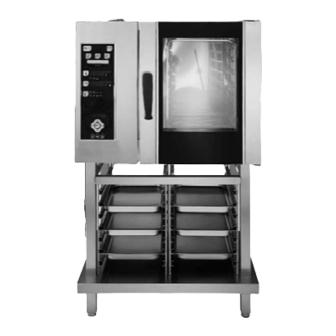
Page 2: Installation Diagram
Do not store or use gasoline or other flammable vapors or liquids in the vicinity of this or any other appliance. WARNING Improper installation, adjustment, alteration, service or maintenance can cause property damage, injury or death. Read the installation, operating and maintenance instructions thoroughly before installing or servicing this equipment. - Page 3 " 898 mm " 142 mm " 142 mm (A ^) (B ^) (A ^) " " 73 mm (A ^) (C ^) (B ^) 55 mm " 73 mm " 500 mm I - Power supply cable inlet B - Water supply connection (0.5- 5 °F) C - Water drain connection N - Steam condens.
- Page 4 " 1208 mm " 145 mm " 145 mm (A ^) " (B ^) " 77.5 mm (A ^) 77.5 mm " (A ^) (C ^) (B ^) 62.5 mm " 500 mm I - Power supply cable inlet B - Water supply connection (0.5- 5 °F) C - Water drain connection N - Steam condens.
- Page 5 " 898 mm " 142 mm " 142 mm (A ^) (B ^) (A ^) " " 73 mm (A ^) (C ^) (B ^) 55 mm " 73 mm " 500 mm I - Power supply cable inlet B - Water supply connection (0.5- 5 °F) C - Water drain connection N - Steam condens.
- Page 6 " 1208 mm " 145 mm " 145 mm (A ^) " (B ^) " 77.5 mm (A ^) 77.5 mm (A ^) " (C ^) (B ^) 62.5 mm " 500 mm I - Power supply cable inlet B - Water supply connection (0.5- 5 °F) C - Water drain connection N - Steam condens.
- Page 7 " 994 mm " 176 mm " 176 mm (A ^) " (B ^) 74 mm (A ^) " (A ^) (B ^) 63 mm " 59 mm " 176 mm " 500 mm I - Power supply cable inlet B - Water supply connection (0.5- 5 °F) C - Water drain connection N - Steam condens.
- Page 8 " 1240 mm " 164 mm " 164 mm (A ^) " (B ^) 59 mm (A ^) " 54 mm (A ^) (C ^) (B ^) " 62 mm " 164 mm " 500 mm I - Power supply cable inlet B - Water supply connection (0.5- 5 °F) C - Water drain connection N - Steam condens.
-
Page 9: Table Of Contents
7.2 Replacing CONSUMABLE components ... 29 7.3 Special cleaning instructions ... 29 - CONTROL PANEL FIGURES ... 97 Rating plate PNC 9PDX 260462 05 2. TABLE 1: TECHNICAL DATA 6GN1/1 (AOS061E) 260450-260510 260462 260456 26045 260462 260451-260511 260463 260457 2604 ° ° ° 3 N~... -
Page 10: Main Features
I. MAIN FEATURES 1. DESCRIPTION OF APPLIANCE This booklet describes a number of appliance models. For more detailed information about the model in your possession, refer to "Technical Data" table 1. The appliance has the following features: • Digital temperature controlle. •... -
Page 11: Precautions
10 GN 2/1 GRIDS 267083 PNC * 269083 ° ° CONVECTOR ° BOILER ** 208V 3ph 208V 3ph SUPPLY VOLTAGE 60Hz 60Hz 80amps 80amps Total Watts 25 kW 25 kW Maximum load capacities 220 lbs. 220 lbs. (food) (100 kg) (100 kg) 461 lbs 461 lbs... -
Page 12: Safeguarding The Environment
• Our appliances have been studied and optimized to give the highest performance. This appliance is intended for industrial use only and is specifically designed to cook food. Any other use will be considered “improper use” and will void the warranty and manufacturer liability. -
Page 13: Instructions For Installation
II. INSTRUCTIONS FOR INSTALLATION Important: The oven outer panels must be removed to perform the operations described in this chapter. Since the appliance must be switched on to make certain adjustments, exercise the utmost care when working in the vicinity of live electrical parts. 1. -
Page 14: Installing The Power Supply Cable
3.1 INSTALLING THE POWER SUPPLY CABLE To access the power supply cable connection terminal board, proceed as follows: Model 6 - 10 - 20 GN • Remove the left side panel. • Connect the power supply cable to the terminal board accord- ing to the instructions given in the wiring diagram and fasten the power supply cable by means of strain-relief fitting (not furnished with the oven). -
Page 15: Safety Devices
- OVEN level C - Connect drain fitting “C” to a drain pipe of the same diameter which is between 0.5 and 3 metres in length and is resistant to temperatures of at least 100°C. The drain pipe must be siphoned (height 80 mm) to an open drain “O”... -
Page 16: Instructions For Use
III. INSTRUCTIONS FOR USE Before switching on the appliance, read this instruction booklet carefully because it contains important information concerning correct use of the appliance. If you require further information about the oven's features and cooking performance, consult your local dealer. ANY POTENTIAL USER OF THE EQUIPMENT SHOULD BE TRAINED IN SAFE AND CORRECT OPERATING PROCEDURES. -
Page 17: Description Of The Control Panel
3. DESCRIPTION OF THE CONTROL PANEL 3.1 INTRODUCTION To aid understanding of the operation of the oven, find the folding double page showing the control panel for your model among those included at the back of this handbook and then open it out and keep it open while reading this section. -
Page 18: Additional Functions
Low speed cycle (fan): for delicate cooking such as for baking cakes. Can be combined with any other cycle. Reduced power cycle (heating): for delicate cooking such as for baking cakes. Can be combined with any other cycle. Cooking with ECO-DELTA: for cooking large pieces of food (5kg and above, e.g. -
Page 19: Using The Oven
USING THE OVEN OPERATING LEVEL A and C (C = Convect) 4. INTRODUCTION Cooking of food is carried out by heating it and can be achieved in a specific MODE, at a specific TEMPERATURE, a specific TIME and HUMIDITY level. Therefore these parameters must be set in order to execute a COOKING CYCLE. -
Page 20: Setting The Cooking Time
After 5 seconds the COOKING TEMPERATURE stops flashing to indicate that it has been SET. Note The temperature of the steam cycle is automatically set at 212°F(100°C). You can, however, set low temperature steam from 77°F to 210°F(25° to 99°C) by turning the knob. Note 2 With the COMBI cycle it is possible to do a dough proving cycle by setting a temperature below 122°F(77 to 121°F), 50°C(25 to... - Page 21 Note: Press the button again to switch from the PROBE function to the TIME function: the relative LED on the DISPLAY will light up. 4) Start the cycle. Press the Cooking Start/Stop button. 5) Stop the cycle. When the required product core temperature reaches the set temperature the oven stops automatically as described in heading 4.3.7 STOPPING THE COOKING CYCLE and elapsed cooking cycle time is shown on the large DISPLAY.
- Page 22 4.3.9 UTILITIES - Switch on the oven by pressing button I. - Set a cooking cycle for the following UTILITIES: UTILITIES with cycle presetting; this is not necessary for the other utilities as they are already specific cycles. - Press button U (UTILITY): - The green UTILITY LEDs will light up and one will be flashing.
-
Page 23: Automatic Controls
4.4 AUTOMATIC CONTROLS Introduction: the automatic controls make it possible to perform cooking cycles in special modes and also to store cycles after manual setting. For information on manual setting procedures refer first to heading 4.3 MANUAL CONTROLS. Note: If the oven is switched off after you have set up a cooking cycle manually the data you have entered will be lost since, in manual mode, the controller does not store the cooking cycle. - Page 24 4.4.2 SETTING THE TIME, DATE AND DELAY START - TIME and DATE - Proceed as follows to set the TIME and DATE: 1) Switch on the oven by pressing button I. 2) Hold down button TM until you hear a beep and the HOUR digits start flashing.
-
Page 25: Using Preset Programs
4) Press button P to select the recipe number. NUMBER OF RECIPE SELECTED P : C ON F I RM 5) Select (while flashing) the RECIPE number in which you want to store the cycle you have just set up and confirm the number by pressing button P. -
Page 26: Information And Error Codes
• Fast maturing process - time saving and use of fresh cut. • Significant less cooking shrinkage, 5-8 % (depend on food quality and selected core temperature). • Remarkable gain of portions for selling. • Dramatic energy-saving due to the intelligent EFS - LTC program. -
Page 27: Switching Off In The Event Of A Fault
End - End of a cycle or function. FILL - Boiler filling. (Ensure water supply tap/cock are open). Hold - Cooking option, HOLD function active. LOAd - Place the food in the oven. oPEn - Boiler discharge valve opening. PrEH - (TIME TM / PRB DISPLAY)Boiler preheating. PrEH -(COMPARTMENT TEMP. -
Page 28: Periodical Maintenance Of The Boiler
5) - Press the START/STOP button to start the cycle. ————— SEMIAUTOMATIC Cycle only (A-C) ————— The cycle will commence when the temperature automatically reaches 100 °C in the oven chamber. 6) - The 1st cleaning phase (STEAM cycle) ends after 5 minutes, as signalled by the audible alarm. -
Page 29: Replacing Consumable Components
IMPORTANT - 1 Insert a rubber hose inside the boiler filler pipe and rinse thoroughly with water to remove all traces of descaling agent. • Refit the filler plug and close the boiler drain (by pressing the relative button). After descaling the boiler, it is good practice to execute a 30- minute STEAM cycle with the oven empty. - Page 30 NO TEXT ON THIS PAGE...