HP 381513-B21 - Smart Array P800 Controller RAID User Manual
For hp proliant servers
Hide thumbs
Also See for 381513-B21 - Smart Array P800 Controller RAID:
- User manual (55 pages) ,
- Technology brief (15 pages) ,
- Reference manual (112 pages)
Table of Contents
Quick Links
See also:
Reference Manual, User Manual
Table of Contents

Related Manuals for HP 381513-B21 - Smart Array P800 Controller RAID


Summary of Contents for HP 381513-B21 - Smart Array P800 Controller RAID
-
Page 1: User Guide
HP Smart Array P800 Controller for HP ProLiant Servers User Guide Part Number 432600-002 August 2007 (Second Edition) - Page 2 Nothing herein should be construed as constituting an additional warranty. HP shall not be liable for technical or editorial errors or omissions contained herein. Bluetooth is a trademark owned by its proprietor and used by Hewlett-Packard Company under license. Audience assumptions This document is for the person who installs, administers, and troubleshoots servers and storage systems.
-
Page 3: Table Of Contents
Contents Hardware features ........................5 Main components on the board ........................5 Controller specifications ..........................5 Overview of the installation procedure .................... 7 Installing the controller in an unconfigured server ..................7 Installing the controller in a previously-configured server................. 7 Installing the controller hardware .................... - Page 4 Battery pack LEDs............................ 34 Diagnostic tools ............................35 Electrostatic discharge ......................... 37 Preventing electrostatic discharge ......................37 Grounding methods to prevent electrostatic discharge .................. 37 Regulatory compliance notices ..................... 38 Federal Communications Commission notice....................38 Modifications............................38 Cables ..............................38 Canadian notice .............................
-
Page 5: Hardware Features
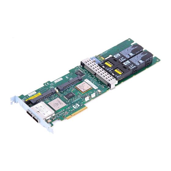
Hardware features Main components on the board Item ID Description Connector for SAS miniports 1E and 2E (external), each 4x wide Heartbeat LED (flashes green when operating normally and amber if the board has failed) Activity LED for external ports SAS port 3I (internal), 4x wide SAS port 4I (internal), 4x wide Cache module (also known as BBWC or array accelerator) - Page 6 Temperature range Operating, 10° to 55°C (50° to 131°F) Storage, -30° to 60°C (-22° to 140°F) Relative humidity Operating, 10% to 90% (noncondensing) Storage, 5% to 90% RAID levels supported 0, 1, 1+0, and 5; also 6 if the batteries are used Type of edge connector PCIe x8 PCIe transfer rate...
-
Page 7: Overview Of The Installation Procedure
Overview of the installation procedure Installing the controller in an unconfigured server New HP ProLiant server models autoconfigure when they are powered up for the first time. For more information about the autoconfiguration process, see the server-specific setup and installation guide or the HP ROM-Based Setup Utility User Guide. - Page 8 Reconnect peripheral devices and the AC power supply to the server. Power up peripheral devices. Power up the server. Update the controller firmware ("Methods for updating the firmware" on page 12). (Optional) Set this controller as the boot controller using ORCA ("Setting a controller as the boot controller"...
-
Page 9: Installing The Controller Hardware
Installing the controller hardware Preparing the server Back up all data. Close all applications. Power down the server. CAUTION: In systems that use external data storage, be sure that the server is the first unit to be powered down and the last to be powered back up. Taking this precaution ensures that the system does not erroneously mark the drives as failed when the server is powered up. -
Page 10: Connecting Storage Devices
CAUTION: Do not operate the server for long periods with the access panel open or removed. Operating the server in this manner results in improper airflow and improper cooling that can lead to thermal damage. Connecting storage devices You can connect SAS or SATA drives to the controller internally ("Connecting internal storage"... -
Page 11: Sas Cable Part Numbers
If the enclosure uses a mini SAS 4x connector, pull back the tab on the cable connector, insert the cable connector into the enclosure connector, and then release the tab. Power up the enclosure. Power up the server. SAS cable part numbers To order additional cables, use the option kit part number. -
Page 12: Updating The Firmware
Updating the firmware Methods for updating the firmware To update the firmware on the server, controller, or hard drives, use Smart Components. These components are available on the Firmware Maintenance CD. A more recent version of a particular server or controller component might be available on the support page of the HP website (http://www.hp.com/support). -
Page 13: Configuring An Array
Configuring an array Utilities available for configuring an array Three utilities are available for configuring an array on an HP Smart Array controller: ORCA, CPQONLIN, and ACU. ORCA is a simple utility that is used mainly to configure the first logical drive in a new server before the operating system is loaded. -
Page 14: Setting The Boot Controller And Controller Order
Setting the boot controller and controller order Setting a controller as the boot controller The following procedure enables you only to set a controller as the boot controller. If you also want to adjust the boot order settings of other controllers in the system, use RBSU instead ("Setting the controller order"... - Page 15 For more information about using RBSU, refer to the HP ROM-Based Setup Utility User Guide or the server setup and installation guide. These documents are both available on the Documentation CD supplied in the server kit. Setting the boot controller and controller order 15...
-
Page 16: Installing Device Drivers And Management Agents
Installing device drivers and Management Agents Installing device drivers The drivers for the controller are located on the Support Software CD or the SmartStart CD that is provided in the controller kit. Updates are posted to the HP website (http://www.hp.com/support). Using the Support Software CD: Instructions for installing the drivers from the Support Software CD are given in the leaflet that is supplied with the CD. -
Page 17: Upgrading Or Replacing Controller Options
Upgrading or replacing controller options Replacing or adding a battery CAUTION: Electrostatic discharge can damage electronic components. Be sure you are properly grounded before beginning this procedure. For more information, see "Electrostatic Discharge (on page 37)." Close all applications, and then power down the server. This procedure flushes all data from the cache. - Page 18 While holding the battery assembly, tilt the clip until it is at about 30 degrees to the batteries, and then push the clip in line with the clip hinges until the clip detaches from the batteries. The rest of the procedure depends on whether you are replacing a battery or adding one. If you are replacing a battery, continue with the next step.
- Page 19 Position the new battery and the remaining good battery as indicated, and then push them together and slide them until they are aligned. The batteries combine into one unit. Install the battery clip. Position the clip so that the hinges on the clip are next to the appropriate hinge pillars on the batteries.
- Page 20 Position the batteries so that the pegs A on the underside of each battery are in the appropriate holes B on the controller board and pegs C are in slots D. Slide the batteries toward the board bracket until they are firmly seated against the connectors on the cache module.
-
Page 21: Replacing The Cache Module Or Controller
Push the clip firmly at both ends (2) until it clicks into place under the controller board. Reinstall the controller in the server. After installing a battery pack, you might see a POST message during reboot indicating that the array accelerator (cache) is temporarily disabled. - Page 22 Pull the flanges on the battery clip outward (1), and then swivel the clip 180 degrees so that it rests on the batteries (2). Swivel the latches on the DIMM connector outward (1). Slide the battery assembly and the cache module off the controller board (2). The procedure at this point depends on whether you are replacing the controller or the cache module.
- Page 23 Position the batteries so that the pegs A on the underside of each battery are in the appropriate holes B on the controller board and pegs C are in slots D. Slide the batteries toward the board bracket until the connectors on the cache module are firmly seated in the DIMM connector.
- Page 24 Push the clip firmly at both ends (2) until it clicks into place under the controller board. Reinstall the controller in the server. Upgrading or replacing controller options 24...
-
Page 25: Replacing, Moving, Or Adding Hard Drives
Replacing, moving, or adding hard drives Identifying the status of a hard drive When a drive is configured as a part of an array and connected to a powered-up controller, the condition of the drive can be determined from the illumination pattern of the hard drive status lights (LEDs). Item Description Fault/UID LED (amber/blue) -
Page 26: Recognizing Hard Drive Failure
Online/activity Fault/UID LED Interpretation LED (green) (amber/blue) Flashing regularly Amber, flashing Do not remove the drive. Removing a drive may terminate the (1 Hz) regularly (1 Hz) current operation and cause data loss. The drive is part of an array that is undergoing capacity expansion or stripe migration, but a predictive failure alert has been received for this drive. -
Page 27: Effects Of A Hard Drive Failure
Effects of a hard drive failure When a hard drive fails, all logical drives that are in the same array are affected. Each logical drive in an array might be using a different fault-tolerance method, so each logical drive can be affected differently. -
Page 28: Replacing Hard Drives
Replacing hard drives The most common reason for replacing a hard drive is that it has failed. However, another reason is to gradually increase the storage capacity of the entire system. If you insert a hot-pluggable drive into a drive bay while the system power is on, all disk activity in the array pauses for a second or two while the new drive is spinning up. -
Page 29: Automatic Data Recovery (Rebuild)
Automatic data recovery (rebuild) When you replace a hard drive in an array, the controller uses the fault-tolerance information on the remaining drives in the array to reconstruct the missing data (the data that was originally on the replaced drive) and write it to the replacement drive. This process is called automatic data recovery, or rebuild. If fault tolerance is compromised, this data cannot be reconstructed and is likely to be permanently lost. - Page 30 Observation Cause of rebuild termination None of the drives in the array have One of the drives in the array has an illuminated amber Fault LED. experienced an uncorrectable read error. The replacement drive has an The replacement drive has failed. illuminated amber Fault LED.
-
Page 31: Upgrading Hard Drive Capacity
Upgrading hard drive capacity You can increase the storage capacity on a system even if there are no available drive bays by swapping drives one at a time for higher capacity drives. This method is viable as long as a fault-tolerance method is running. -
Page 32: Adding Drives
Power up the system. If a 1724 POST message appears, drive positions were changed successfully and the configuration was updated. If a 1785 (Not Configured) POST message appears: Power down the system immediately to prevent data loss. Return the drives to their original locations. Restore the data from backup, if necessary. -
Page 33: Diagnosing Array Problems
Diagnosing array problems Controller board runtime LEDs Immediately after the server is powered up, the controller runtime LEDs illuminate briefly in a predetermined pattern as part of the POST sequence. At all other times during server operation, the illumination pattern of the runtime LEDs indicates the status of the controller, as described in the following table. -
Page 34: Battery Pack Leds
LED ID Color LED name and interpretation Green CR504: Gas Pedal LED. This LED, together with item 10, indicates the amount of controller CPU activity. For details, see the following table. Green CR503: Idle Task LED. This LED, together with item 9, indicates the amount of controller CPU activity. -
Page 35: Diagnostic Tools
LED3 pattern LED4 pattern Interpretation — One blink every The system is powered down, and the cache contains data that has two seconds not yet been written to the drives. Restore system power as soon as possible to prevent data loss. Data preservation time is extended any time that 3.3 V auxiliary power is available, as indicated by LED 2. - Page 36 To use Server Diagnostics: Insert the SmartStart CD into the server CD-ROM drive. Click Agree when the license agreement appears, and click the Maintenance tab. Click Server Diagnostics, and follow the on-screen prompts and instructions. Diagnosing array problems 36...
-
Page 37: Electrostatic Discharge
Electrostatic discharge Preventing electrostatic discharge To prevent damaging the system, be aware of the precautions you need to follow when setting up the system or handling parts. A discharge of static electricity from a finger or other conductor may damage system boards or other static-sensitive devices. -
Page 38: Regulatory Compliance Notices
EMC Directive 2004/108/EC Compliance with these directives implies conformity to applicable harmonized European standards (European Norms) which are listed on the EU Declaration of Conformity issued by Hewlett-Packard for this product or product family. This compliance is indicated by the following conformity marking placed on the product:... -
Page 39: Bsmi Notice
This marking is valid for non-Telecom products and EU harmonized Telecom products (e.g. Bluetooth). This marking is valid for EU non-harmonized Telecom products. *Notified body number (used only if applicable—refer to the product label) Hewlett-Packard GmbH, HQ-TRE, Herrenberger Strasse 140, 71034 Boeblingen, Germany BSMI notice Japanese class A notice... -
Page 40: Taiwan Battery Recycling Notice
WARNING: There is a risk of explosion, fire, or personal injury if a battery pack is mishandled. To reduce this risk: Do not attempt to recharge the batteries if they are disconnected from the controller. Do not expose the battery pack to water, or to temperatures higher than 60°C (140°F). Do not abuse, disassemble, crush, or puncture the battery pack. -
Page 41: Acronyms And Abbreviations
Acronyms and abbreviations Array Configuration Utility Advanced Data Guarding (also known as RAID 6) Array Diagnostics Utility BBWC battery-backed write cache CPQONLIN NetWare Online Array Configuration Utility DIMM dual inline memory module light-emitting diode ORCA Option ROM Configuration for Arrays PCIe peripheral component interconnect express POST... -
Page 42: Index
Index device drivers, installing 16 diagnostic tools 35 drive failure, detecting 26 ACU (Array Configuration Utility) 13 drive LEDs 25 adding drives 32 drivers 16 ADU (Array Diagnostic Utility) 35 drives, moving 31 Array Configuration Utility (ACU) 13 array controller installation overview 7 Array Diagnostic Utility (ADU) 35 array expansion 32 electrostatic discharge 37... - Page 43 Japanese notice 39 Server Diagnostics utility 35 spares, battery pack, part number 5 spares, cable part numbers 11 specifications, controller 5 Korean notices 39 static electricity 37 status lights, battery pack 34 status lights, controller 33 status lights, hard drive 25 LEDs, battery pack 34 storage capacity, increasing 31 LEDs, controller 33...