Table of Contents
Quick Links
EN
2 0 . 1 0 - 5 0 4 4 5 9 6 _ 0 3
T r a n s l a t i o n f r o m o r i g i n a l
M L G
2 5 0 F S - 3 5 0 F S - 5 0 0 F S
I n s t a l l a t i o n m a n u a l
Q
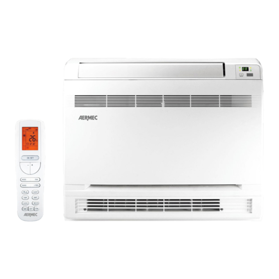
MULTISPLIT - CONSOLE
C o o l i n g c a p a c i t y 2 , 7 k W ÷ 5 , 2 k W
H e a t i n g c a p a c i t y 2 , 8 k W ÷ 5 , 3 k W
w w w . a e r m e c . c o m
Table of Contents

Related Manuals for AERMEC MLG 250FS


Summary of Contents for AERMEC MLG 250FS
- Page 1 2 0 . 1 0 - 5 0 4 4 5 9 6 _ 0 3 T r a n s l a t i o n f r o m o r i g i n a l M L G 2 5 0 F S - 3 5 0 F S - 5 0 0 F S I n s t a l l a t i o n m a n u a l MULTISPLIT - CONSOLE...
-
Page 2: Table Of Contents
INDEX GAS R32 - WARNINGS..........................................4 WARNINGS ..............................................6 UNIT TYPE ...............................................10 CHARACTERISTICS ..........................................10 NOTES ON OPERATION ........................................10 ACCESSORIES ............................................12 TECHNICAL DATA ..........................................12 NOTES FOR INSTALLATION OF UNIT ....................................13 DIMENSIONS AND WEIGHTS......................................15 TECHNICAL DIMENSIONS ........................................16 TECHNICAL DIMENSIONS - JIG KIT ....................................16 MINIMUM CLEARANCES FOR INDOOR UNIT ................................17 INSTALLATION OF THE INDOOR UNIT ..................................19 FITTING THE REFRIGERANT LINES ....................................23 CONDENSATE DRAIN .........................................25... - Page 3 Dear customer, Thank you for choosing an AERMEC product. It is the fruit of many years of experience and special design studies and has been made of the highest grade materials and with cutting edge technology. In addition, all our products bear the CE mark indicating that they meet the requirements of the European Machine Directive regarding safety.
-
Page 4: Gas R32 - Warnings
GAS R32 - WARNINGS 1. GAS R32 - WARNINGS WARNINGS FOR MAINTENANCE OR REPAIR THESE PROCEDURES MAY ONLY BE FOLLOWED GAS R32 GENERAL WARNINGS BY SPECIALISED TECHNICIANS OR QUALIFIED WARNING PERSONNEL. Please read this manual carefully before Please follow the steps below: using the unit. - Page 5 WARNING: Do not use means to accelerate the defrosting process or to clean, other than those recommended by the manufacture. Should repair be necessary, contact your nearest authorized Service Centre. Any repairs carried out by unqualified personnel may be dangerous. The appliance shall be stored in a room without continuously operating ignition sources.
-
Page 6: Warnings
WARNINGS cables, plug or power socket overheating, which could present a fire risk. • Ensure that the air conditioner is connected to the power supply or to a power socket with the correct WARNING: Strictly observe the warnings below. Failure voltage and frequency. - Page 7 panel is completely closed, as shown in the following • Periodically check that the installation conditions of the unit have not been altered: have the system example. • The wiring diagrams are subject to a continuous checked by “Personnel with specific technical skills”. update.
- Page 8 PRECAUTIONS FOR USE • When one of the following phenomena occur, switch the unit off and disconnect it from the power supply, then contact your local Aftersales • Ensure the equipment is not used by children or Service (interventions must only be carried out by disabled people without suitable supervision;...
- Page 9 DISCLAIMER • When heating, select a moderate temperature. • Limit the room’s exposure to direct sunlight using AERMEC DOES NOT ASSUME ANY RESPONSIBILITY blinds or by leaving the windows ajar. FOR DAMAGES TO THE UNIT OR WARRANTY LOSS • Do not place hot devices, flames or other heat IN CASE: sources near the unit.
-
Page 10: Unit Type
UNIT TYPE NOTES ON OPERATION 1. NOTES ON OPERATION Indoor units in split-system air conditioners for CONSOLE installation are designed to be installed on walls indoors. DEFROSTING THE OUTDOOR UNIT The air filter is easily accessible to enable regular cleaning. Air conditioners for CONSOLE installation are supplied When the outside temperature is low but there is complete with a remote control. - Page 11 AIR PURIFIER (COLD PLASMA) Capable of reducing pollutants breaking down their mole- cules using electric discharges, causing the splitting of the water molecules in the air into positive and negative ions. These ions neutralise the molecules of the gaseous pollut- ants obtaining products that are normally present in clean air.
-
Page 12: Accessories
ACCESSORIES 250FS 350FS 500FS WRCA • • • CC2* • • • Legend • Compatible – Not compatible * The accessory CC2 version 01 is compatible with the indoor units of the MLG_FS serie, from version 01. TECHNICAL DATA MLG250FS MLG350FS MLG500FS Nominal cooling performances... -
Page 13: Notes For Installation Of Unit
INSTALLATION measures to avoid heat dispersion and the NOTES FOR INSTALLATION OF UNIT consequent formation of condensate. Incorrect installation of the pipes can result in water leaks, wetting furniture and other items in the room. WARNINGS CONCERNING INSTALLATION NOISE • The unit and its accessories must only be installed and wired by professionals with the necessary •... - Page 14 WIRING • The unit and its accessories must only be installed and wired by professionals with the necessary technical qualifications in installation, conversion, extension and maintenance of the systems and who EARTHING: are trained to perform operational and safety checks Check the earth cable is connected to the on these systems.
-
Page 15: Dimensions And Weights
DIMENSIONS AND WEIGHTS MLG_FS MLG_FS Without Net weight package (mm) (mm) (mm) (kg) MLG250FS 15,5 MLG350FS 15,5 MLG500FS 15,5 Gross With package (mm) (mm) (mm) weight (kg) MLG250FS 18,5 MLG350FS 18,5 MLG500FS 18,5 Carton Box Example... -
Page 16: Technical Dimensions
TECHNICAL DIMENSIONS MLG_FS (mm) (mm) (mm) MLG250FS MLG350FS MLG500FS TECHNICAL DIMENSIONS - JIG KIT MLG_FS (mm) (mm) (mm) MLG250FS MLG350FS MLG500FS... -
Page 17: Minimum Clearances For Indoor Unit
1. MINIMUM CLEARANCES FOR INDOOR UNIT MINIMUM CLEARANCES FOR INDOOR UNIT • Install the unit further than 1m away from other electrical appliances such as TVs, radios, audio equipment, etc. CHOOSING THE INSTALLATION AREA FOR THE • Do not install the unit in a location where it could be INDOOR UNIT affected by inflammable gas leaks. - Page 18 Floor installation Wall mounting (with support) Installing semi-recessed Niche installation...
-
Page 19: Installation Of The Indoor Unit
INSTALLATION OF THE INDOOR UNIT (1) Open the front panel To install the unit you must follow the following steps Open the front panel to access the screws holding the front grille; Remove the 4 screws holding the front grille; Remove the front grille;... - Page 20 1. Choose the mounting position on the wall. tubes), made according to the type of installation 2. Find the points where drill the wall using as a required and based on distances specified in the reference the cardboard template supplied. Mark the schemes at the bottom.
- Page 21 Position for drilling holes of service: Wall SX links DX links Muro SX links DX links DX/SX links Floor Floor pre-cut side (right and left sides)
- Page 22 SELECTION OF AIR DELIVERY This type of unit draws air laterally and enters the envi- ronment through two turns distinct, one high and one low; but you can rule out Lower discharge through the following steps: Open the front panel; Use the selector outlet (located on the left enables the double-locked, right single upper delivery) CAUTION:...
-
Page 23: Fitting The Refrigerant Lines
FITTING THE REFRIGERANT LINES To prepare the copper pipes, proceed as follows: External Pipe Tightening Pipe thickness 1. Measure the inner and outer pipe precisely. Diameter Torque 2. Use a pipe which is slightly longer than the inch (mm) measurement taken. 1/4˝... - Page 24 Fig. A Fig. B Fig. C Fig. D Fig. E Fig. F...
-
Page 25: Condensate Drain
1. CONDENSATE DRAIN CONDENSATE DRAIN • The outlet direction of the condensate discharge hose can be chosen according to the plant requirements of the indoor unit. • The diameter of the condensate discharge hose must be the same as - or greater than - the diameter of the connection pipe. -
Page 26: Electrical Wirings
1. ELECTRICAL WIRINGS ELECTRICAL WIRINGS fans. • Do not modify the circuits inside the air conditioner. The manufacturer cannot be held responsible for • Before carrying out any work, switch off the power any damage or malfunction due to incorrect line supply to the air conditioner. - Page 27 NOTE: • Circuit Breaker and Power Cord Specifications are selected according to the Rated Power Input (Rated Current Input) of the Unit. Rated Power Input (Rated Current Input) is “Maximum” Power Input (“Maximum” Current Input) of the Unit according to EN 60335-1 and EN 60335-2-40.
-
Page 28: Wiring Diagram
WIRING DIAGRAM MLG250FS - MLG350FS - MLG500FS WARNING SWITCH MOTOR ROOM TEMP. TUBE TEMP. RECEIVER AND Please don't touch any electronic SELECT component or terminal when the SENSOR SENSOR DISPLAY BOARD machine is running,stopping or has been powered off for less DISPLAY than 3 minutes to prevent electric shock ! -
Page 29: Routine Checks Following Installation
1. ROUTINE CHECKS FOLLOWING ROUTINE CHECKS FOLLOWING INSTALLATION INSTALLATION ITEMS TO CHECK POSSIBLE ANOMALY NOTES Is the unit firmly fixed? The unit could fall, vibrate or make noise. Was the unit checked for refrigerant Insufficient output. leaks? Is the thermal insulation sufficient? It could cause condensate and dripping water. -
Page 30: Maintenance
MAINTENANCE GENERAL NOTES CHECK BEFORE STARTING • Disconnect the power supply before cleaning the • Check to make sure that the inlet and outlet are not unit. obstructed by objects on both units, external and • Disconnect the power supply when the air internal. -
Page 31: Troubleshooting
1. TROUBLESHOOTING TROUBLESHOOTING Anomaly Possible causes The unit cannot be started. • The power supply is not connected. • Check if the power supply cable is damaged. • Check for anomalies on the power supply. • Voltage is too low. The units stops after operating a while. -
Page 32: Error Code List
ERROR CODE LIST CODE DESCRIPTION Outdoor condenser inlet pipe temperature sensor is open/short- circuited Outdoor condenser outlet pipe temperature sensor is open/short- circuited Liquid valve temperature sensor is open/short-circuited Gas valve temperature sensor is open/short-circuited Malfunction protection of jumper cap Wrong connection of communication cable or expansion valve malfunction detection mode Wrong connection of communication cable or expansion valve malfunction High pressure protection for the system... - Page 33 CODE DESCRIPTION Compressor losing of synchronism Compressor demagnetization protection Compressor start failure Compressor blockage Overspeed Indoor unit and outdoor unit do not match Drive module reset Min cooling or heating Rating cooling or heating Max cooling or heating Middle cooling or heating Phase current overcurrent protection Drive board communication malfunction Module temperature sensor is open/short-circuited...
- Page 36 DOWNLOAD THE LATEST VERSION: DOWNLOAD THE LATEST VERSION: TÉLÉCHARGER LA DERNIÈRE VERSION: TÉLÉCHARGER LA DERNIÈRE VERSION: http://www.aermec.com/qrcode.asp?q=13730 http://www.aermec.com/qrcode.asp?q=13731 http://www.aermec.com/qrcode.asp?q=13749 A E R M E C S . p . A . V i a R o m a , 9 9 6 - 3 7 0 4 0 B e v i l a c q u a ( V R ) - I t a l y T e l .