Makita AN510H - Construction Nailer Manual
- Instruction manual (61 pages) ,
- Instruction manual (56 pages) ,
- Instruction manual (12 pages)
SPECIFICATIONS
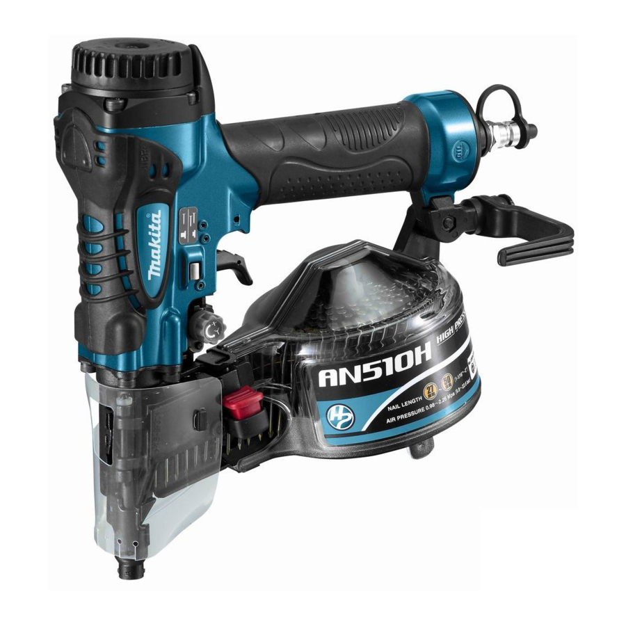
| Model | AN510H |
| Air pressure | 0.98 - 2.26 MPa (9.8 - 22.6 bar) |
| Nail length | Wire-collated coil nail 27 mm - 50 mm Sheet-collated coil nail 25 mm - 50 mm |
| Nail capacity | Wire-collated coil nail 200 pcs., 400 pcs. Sheet-collated coil nail 200 pcs. |
| Min. hose diameter | 5.0 mm |
| Pneumatic tool oil | ISO VG32 or equivalent |
| Dimensions (L X H X W) | 260 mm X 255 mm X 111 mm |
| Net weight | 1.4 kg |
Symbols
The following show the symbols used for the equipment. Be sure that you understand their meaning before use.
![]() Read instruction manual.
Read instruction manual.![]() Wear safety glasses.
Wear safety glasses.![]() Do not use on scaffoldings, ladders.
Do not use on scaffoldings, ladders.
 Read instruction manual.
 Wear safety glasses.
 Do not use on scaffoldings, ladders.
Intended use
The tool is intended for the preliminary interior work such as fixing floor joists or common rafters and framing work in 2 "x 4" housing.
Noise
The typical A-weighted noise level determined according to EN792:
Sound pressure level (LpA): 83 dB (A)
Sound power level (LWA): 96 dB (A)
Uncertainty (K): 3 dB (A)
Wear ear protection
Vibration
The vibration total value determined according to EN792:
Vibration emission (ah): 3.5 m/s2
Uncertainty (K): 1.5 m/s2

Pneumatic nailer/stapler safety warnings
Read all safety warnings and all instructions. Failure to follow the warnings and instructions may result in serious injury, electric shock and/or fire.
Save all warnings and instructions for future reference.
For personal safety and proper operation and maintenance of the tool, read this instruction manual before using the tool.
General safety
Personal protective equipments
- Always wear safety glasses to protect your eyes from dust or fastener injury.
![]()
It is an employer's responsibility to enforce the use of safety eye protection equipment by the tool operators and by other persons in the immediate working area.
For Australia and New Zealand only Always wear safety glasses and face shield to protect your eyes from dust or fastener injury. The safety glasses and the face shield should conform with the requirements of AS/NZS 1336.


Work area safety
Safety devices
Loading fasteners
Power source
- Always disconnect the air hose and remove all of the fasteners:
Operational safety
- Never use fastener driving tools marked with the symbol "Do not use on scaffoldings, ladders" for specific application for example:
- A fastener will be bent or the tool can become jammed if you mistakenly drive fastener on top of another fastener or strike a knot in the wood. The fastener may be thrown and hit someone, or the tool itself can react dangerously. Place the fasteners with care.
Service
SAVE THESE INSTRUCTIONS.
DO NOT let comfort or familiarity with product (gained from repeated use) replace strict adherence to safety rules for the subject product. MISUSE or failure to follow the safety rules stated in this instruction manual may cause serious personal injury.
INSTALLATION
Selecting compressor

The air compressor must comply with the requirements of EN60335-2-34.
The air compressor must comply with the requirements of ANSI B19.3.
Select a compressor that has ample pressure and air output to assure cost-efficient operation. The graph shows the relation between nailing frequency, applicable pressure and compressor air output.
Thus, for example, if nailing takes place at a rate of approximately 60 times per minute at a compression of 1.77 MPa (17.7 bar), a compressor with an air output over 40 liters/minute is required.
Pressure regulators must be used to limit air pressure to the rated pressure of the tool where air supply pressure exceeds the tool's rated pressure. Failure to do so may result in serious injury to tool operator or persons in the vicinity.
Selecting air hose

Use a high pressure resistant air hose.
Use an air hose as large and as short as possible to assure continuous, efficient nailing operation.

Lubrication
Before and after use, oil the tool with pneumatic tool oil by placing two or three drops into the air fitting. For proper lubrication, the tool must be fired a couple of times after pneumatic tool oil is introduced.

FUNCTIONAL DESCRIPTION
Adjusting the nailing depth
- Always disconnect the hose before adjusting the depth of nailing.
![]()


If nails are driven too deep, turn the adjuster clockwise. If nails are driven too shallow, turn the adjuster counterclockwise.
The adjustable range is 0 - 6 mm. (One full turn allows 0.8 mm adjustment.)
Hook
- Never hang the tool on a waist belt or like. Dangerous accidental firing may result.
![]()

The hook is convenient for hanging the tool temporarily. This hook can be installed on either side of the tool. Install the hook on another side for installation and then secure it with the screw.
Board adapter and floor adapter
- Always disconnect the hose before installing or removing the nose adapter.
![]()

Attach the board adapter for plaster board and other siding boards, and the floor adapter for flooring. The board adapter is attached to the contact arm cover when shipped. When unable to remove the nose adapter easily, use a slotted bit screwdriver and the like.
Replacing nose adapter

Remove the nose adapter by grabbing its top and pulling it down.
To attach the nose adapter to the contact arm, press it onto the contact arm as far as it will go.
Standard air pressure and adjusting method.
Refer to the table below to adjust air pressure. Turn the nailing depth adjuster counterclockwise as far as it will go.
Perform test nailing. If nails are driven too deep, turn the adjuster clockwise. If nailing depth cannot be adjusted as desired, set the air pressure higher.
| Application | Standard air pressure |
| Nailing for wooden beddings | 1.77 MPa (17.7 bar) |
| Nailing for gypsum boards Nailing for interior materials | 0.98 MPa (9.8 bar) |
| Nailing for floor materials | 1.57 MPa (15.7 bar) |
ASSEMBLY
Loading the nailer
- Make sure that the coil support plate is set to the correct step for used nails.
![]()

Disconnect the air hose from the tool. Select nails suitable for your work. Depress the latch lever and open the door and magazine cap.
Lift and turn the coil support plate so that the arrow with nail size indicated on the coil support plate will point to the corresponding graduation increment marked on the magazine. If the tool is operated with the coil support plate set to the wrong step, poor nail feed or malfunction of the tool may result.

Place the nail coil over the coil support plate. Uncoil enough nails to reach the feed claw. Place the first nail in the driver channel and the second nail in the feed claw. Place other uncoiled nails on feeder body. Close the magazine cap slowly until it lock after checking to see that the nail coil is set properly in the magazine.

Connecting air hose
Slip the air socket of the air hose onto the air fitting on the nailer. Be sure that the air socket locks firmly into position when installed onto the air fitting. A hose coupling must be installed on or near the tool in such a way that the pressure reservoir will discharge at the time the air supply coupling is disconnected.
OPERATION
- To drive a nail, you may place the contact element against the workpiece and pull the trigger, or
![]()
- Pull the trigger first and then place the contact element against the workpiece.
![]()


In order to avoid this unexpected nailing, perform as follows;
- For No. (1) method, set the change lever to the
![]() position.
position.
For No. (2) method, set the change lever to the![]() position.
position.
After using the change lever to change the nailing method, always make sure that the change lever is properly set to the position for the desired nailing method.

 position.
 position.
Cutting off the sheet

Tear off the output sheet in the direction of the arrow when using the sheet collated nails.
MAINTENANCE
Jammed nailer

When the nailer becomes jammed, do as follows:
Open the magazine cap and remove the nail coil. Insert a small rod or the like into the ejection port and tap it with a hammer to drive out the nail jamming from the ejection port. Reset the nail coil and close the magazine cap.
Drain tool
Remove the hose from the tool. Place the tool so that the air fitting faces down to the floor. Drain as much as possible.
Cleaning of tool
Iron dust that adhere to the magnet can be blown off by using an air duster.
Cap
When not in use, disconnect the hose. Then cap the air fitting with the cap.

Storage
When not in use, the nailer should be stored in a warm and dry place.
Maintenance of compressor and air hose

After operation, always drain the compressor tank. If moisture is allowed to enter the tool, It may result in poor performance and possible tool failure.
Keep the air hose away from heat (over 60°C, over 140°F), away from chemicals (thinner, strong acids or alkalis). Also, route the hose away from obstacles which it may become dangerously caught on during operation. Hoses must also be directed away from sharp edges and areas which may lead to damage or abrasion to the hose.

To maintain product SAFETY and RELIABILITY, repairs, any other maintenance or adjustment should be performed by Makita Authorized Service Centers, always using Makita replacement parts.
OPTIONAL ACCESSORIES
If you need any assistance for more details regarding these accessories, ask your local Makita Service Center.
NOTE:

Documents / ResourcesDownload manual
Here you can download full pdf version of manual, it may contain additional safety instructions, warranty information, FCC rules, etc.
Thank you! Your question has been received!


Need Assistance?
Do you have a question about the AN510H that isn't answered in the manual? Leave your question here.