Overview
The B299 POPEX Module is an SDI2 compatible, POPIT expansion module that communicates to the control panel over the SDI2 bus. The B299 supports up to 100 POPIT devices by wiring to the POPEX terminal strip and providing one or two addressable POPIT busses.

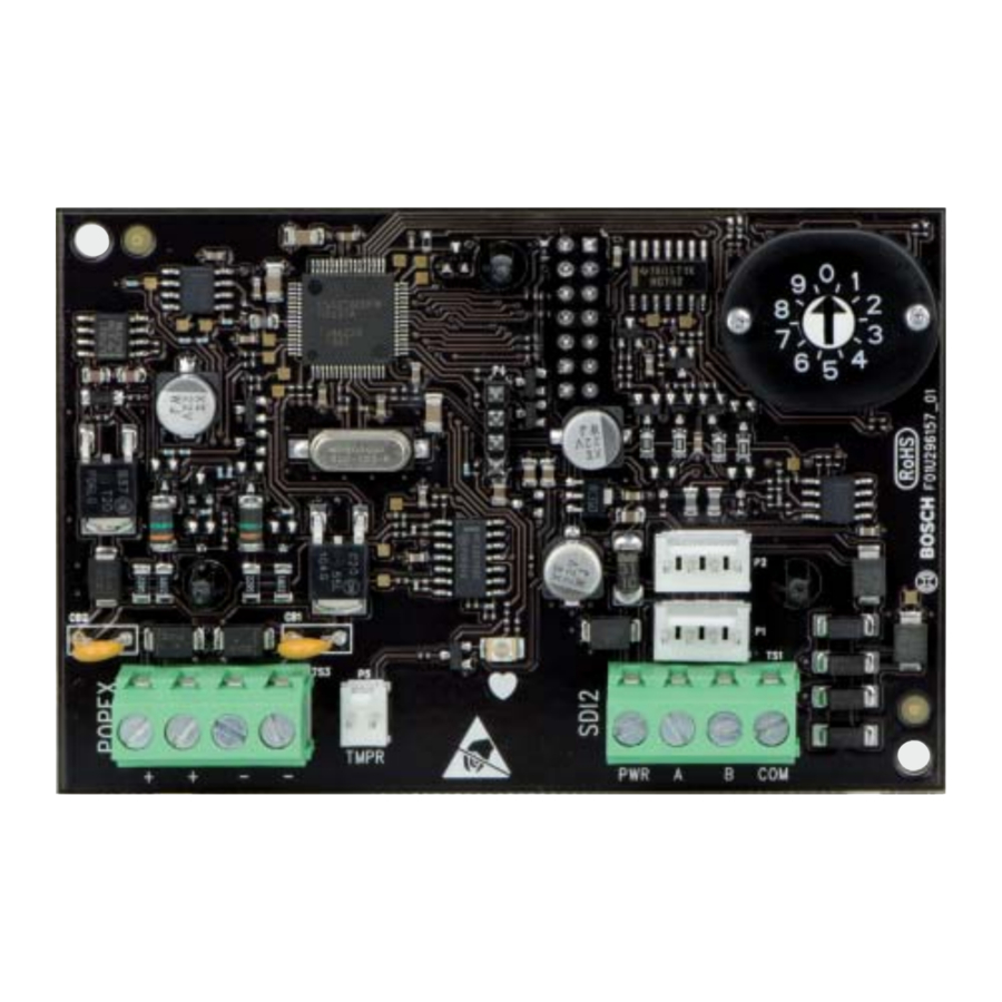
| Callout ― Description |
| 1 ― 3-hole mounting pattern |
| 2 ― Address switch |
| 3 ― SDI2 interconnect wiring connectors (to control panel or additional modules) |
| 4 ― SDI2 terminal strip (to control panel or additional modules) |
| 5 ― Heartbeat LED (blue) |
| 6 ― Tamper switch (optional) connector |
| 7 ― POPEX terminal strip (POPIT Bus)) |
SDI2 address settings
The address switch determines the address for the module. The control panel uses the address to establish communication between itself and the module. The address also determines the associated point numbers. Refer to Configuration for information related to the address switch. Use a slotted screwdriver to set the address switch.

NOTICE!
The module reads the address switch setting during power up. If you change the switches after you apply power to the module, cycle the power to the module in order for the new setting to be enabled.

Set the address switch per the control panel configuration. If multiple B299 modules reside on the same system, each B299 module must have a unique address. Figure 2.1 shows the address switch settings for address 0.
Valid addresses and point numbers per control panel
Valid B299 addresses are dependant on the number of points allowed by a particular control panel.
| Control panel | Valid B299 addresses | Corresponding point numbers |
| B9512G B9512G-E | 0 - 5 | 9 - 99, 100 - 199, 200 - 299, 300 - 399, 400 - 499, 500 - 599 |
| B8512G B8512G-E | 0 | 9 - 99 |
Installation
Set the address switch for the proper address and then install the module into the enclosure. Wire the module to the control panel.

Remove all power (AC and battery) before making any connections. Failure to do so might result in personal injury and/or equipment damage.
Mount the module in the enclosure

Mount the module into the enclosure's 3-hole mounting pattern using the mounting screws and mounting bracket. Refer to Figure 3.1.
| Callout ― Description |
| 1 ― Module with mounting bracket installed |
| 2 ― Enclosure |
| 3 ― Mounting screws (3) |
Mount and wire the tamper switch
You can connect an optional tamper switch for one module in an enclosure.
Installing the optional tamper switch:
- Mount the ICP-EZTS Tamper Switch (P/N: F01U009269) into the enclosure's tamper switch mounting location. For complete instructions, refer to EZTS Cover and Wall Tamper Switch Installation Guide (P/N: F01U003734).
- Plug the tamper switch wire onto the module's tamper switch connector. Refer to Figure 1.1.
Wire to the control panel
Use the control panel terminals labeled R, Y, G, B (PWR, A, B, COM) when wiring to the module. Connect them to the module terminals labeled R, Y, G, B (PWR, A, B, COM). You can also use the SDI2 innerconnect cable. Refer to Figures 3.2 and 3.3.
You can connect modules to the SDI2 data bus by parallel wire run from the control panel to each module, wire from module to module, or a combination of the two techniques. Refer to Figure 3.4.
NOTICE!
Use either the terminal strip wiring or interconnect wiring connector to the control panel. Do not use both. When connecting multiple modules, you can combine terminal strip and interconnect wiring connectors in series.

| Callout ― Description |
| 1 ― Bosch control panel |
| 2 ― B299 POPEX module |

| Callout ― Description |
| 1 ― Bosch control panel |
| 2 ― Innerconnect cable (P/N: F01U79745, included) |
| 3 ― B299 POPEX module |
Wire to the POPIT devices

Refer to Figure 3.4 to wire a zone expansion loop. Wire resistance on each sensor loop must be less than 100 Ω with the detection devices connected. The terminal strip supports 12 to 22 AWG (2.0 to 0.65 mm) wires.
| Callout ― Description |
| 1 ― B299 |
| 2 ― POPIT module (D9127U/T shown) |
| 3 ― D9127 sensor loop |
| 4 ― 33 kΩ EOL resistor (P/N: 15-03130-022) |
| 5 ― POPEX loop 2 (electrically identical to loop 1) |
| 6 ― POPEX loop 1 (electrically identical to loop 2) |
LED descriptions
The module includes one blue heartbeat LED to indicate that the module has power and to indicate the module's current state. Refer to Table 4.1.
Table 4.1: LED descriptions
| Flash Pattern | Function |
Flashes once every 1 sec | Normal state. Indicates normal operation state. |
| 3 quick fl ashes every 1 secx3 | Communication error state. Indicates (the module is in a "no communication state") resulting in an SDI2 communication error. |
ON Steady | LED trouble state. Module is not |
OFF Steady | powered (for OFF Steady only), or some other trouble condition prohibits the module from controlling the heartbeat LED. |
Show the firmware version
To show the firmware version using an LED fl ash pattern:
- If the optional tamper switch is installed:
With the enclosure door open, activate the tamper switch (push and release the switch). - If the optional tamper switch is NOT installed: Momentarily short the tamper pins.
Refer to Figure 5.1 for an example of fl ash patterns.


When the tamper switch is activated (closed to open), the heartbeat LED stays OFF for 3 sec before indicating the firmware version. The LED pulses the major, minor, and micro digits of the firmware version, with a 1 sec pause after each digit.
Flashing patterns do not start until the tamper is open (short is removed). In the following example, the version 1.4.3 shows as LED fl ashes:
[3 sec pause] *___****___*** [3 sec pause, then normal operation].
Configuration
Use the following POPIT programming table to confi gure the POPIT switch block. Switches are designated as being "ON" or "OFF." These are depicted in the table below by the following; ON = o, OFF = blank.
For example the swich settings for x09 looks like this: o, o,o, blank, o,o, blank (On, On, On, Off, On, On, Off ).


Specifications
| Dimensions | 2.9 in x 5.0 in x 0.6 in (73.5 mm x 127 mm x 15.25 mm) |
| Voltage (input) | 12 VDC |
| Current | Standby: 35 mA + total device current Alarm: 35 mA + total device current |
| Operating temperature | 0°C to +50°C (+32°F to +122°F) |
| Relative humidity | 5% to 93% at +32°C (+90°F) non-condensing |
| Terminal wire size | 12 AWG to 22 AWG (2.0 mm to 0.65 mm) |
| SDI2 wiring | Maximum distance - wire size (unshielded wire only): 200 ft (60 m) - 22 AWG (0.65 mm), 500 ft (152 m) - 18 AWG (1.02 mm) |
| POPIT loop wiring | Maximum wire length: 1800 ft (548 m) 22 AWG (0.65 mm), 4497 ft (1370 m) 18 AWG (1.02 mm) |
| Compatibility | Control panel: B9512G/B9512G-E (6 modules), B8512G/B8512G-E (1 module). (Refer to the control panel installation document for the number of supported devices.) POPIT devices: D9127U/T, ZX776Z/ZX794Z PIR, ZX835 TriTech, ZX935Z/ZX938Z PIR, ZX970 TriTech, D278S 12V smoke base, D298S 24V smoke base, F220-B6PM popit smoke (master), F220-B6PS popit smoke base |
Bosch Security Systems, Inc.
130 Perinton Parkway
Fairport, NY 14450
USA
www.boschsecurity.com

Documents / Resources
References
Download manual
Here you can download full pdf version of manual, it may contain additional safety instructions, warranty information, FCC rules, etc.
Thank you! Your question has been received!


Need Assistance?
Do you have a question about the POPEX B299 that isn't answered in the manual? Leave your question here.