Samson 3277-5 Mounting And Operating Instructions
Pneumatic actuator
Hide thumbs
Also See for 3277-5:
- Mounting and operating instructions (66 pages) ,
- Mounting and operating instructions (12 pages) ,
- Mounting and operating instructions (52 pages)

Related Manuals for Samson 3277-5


Summary of Contents for Samson 3277-5
- Page 1 EB 8310-1 EN Translation of original instructions Type 3271 Pneumatic Actuator Type 3277 Pneumatic Actuator Type 3271-5 (120 cm²) Type 3277-5 (120 cm²) Pneumatic Actuators Edition November 2022...
- Page 2 Note on these mounting and operating instructions These mounting and operating instructions assist you in mounting and operating the device safely. The instructions are binding for handling SAMSON devices. The images shown in these instructions are for illustration purposes only. The actual product may vary.
-
Page 3: Table Of Contents
Contents Safety instructions and measures ..............1-1 Notes on possible severe personal injury ............1-4 Notes on possible personal injury ..............1-4 Notes on possible property damage .............1-6 Warnings on the device ................1-6 Markings on the device ................2-1 Actuator nameplate ..................2-1 Design and principle of operation ...............3-1 Direction of action and signal pressure routing ..........3-3 Fail-safe action ...................3-3 3.2.1... - Page 4 Removal ....................11-1 11.1 Removing the actuator from the valve ............11-2 11.2 Relieving the spring compression in the actuator ..........11-4 Repairs ....................12-1 12.1 Returning devices to SAMSON ..............12-1 Disposal ....................13-1 Certificates ....................14-1 Annex......................15-1 15.1 Tightening torques, lubricants and tools ............15-1 15.2 Spare parts ....................15-1...
-
Page 5: Safety Instructions And Measures
Therefore, operators must ensure that the actuator is only used in operating conditions that meet the specifications used for sizing the actuator at the ordering stage. In case operators intend to use the actuator in other applications or conditions than specified, contact SAMSON. SAMSON does not assume any liability for damage resulting from the failure to use the de- vice for its intended purpose or for damage caused by external forces or any other external factors. Î Refer to the technical data and nameplate for limits and fields of application as well as possible uses. - Page 6 − Eye protection and hearing protection while the actuator is operating. Î Check with the plant operator for details on further protective equipment. Revisions and other modifications Revisions, conversions or other modifications of the product are not authorized by SAMSON. They are performed at the user's own risk and may lead to safety hazards, for example. Fur- thermore, the product may no longer meet the requirements for its intended use.
- Page 7 Safety instructions and measures Referenced standards, directives and regulations According to the ignition risk assessment performed in accordance with Clause 5.2 of ISO 80079-36, the non-electrical actuators do not have their own potential ignition source even in the rare incident of an operating fault. As a result, they do not fall within the scope of Directive 2014/34/EU. Î For connection to the equipotential bonding system, observe the requirements specified in Clause 6.4 of EN 60079-14 (VDE 0165-1). The Type 3271 and Type 3277 Actuators are partly completed machinery as defined in the Machinery Directive 2006/42/EC or the Directive 2008 No. 1597 Supply of Machinery (Safety) Regulations 2008.
-
Page 8: Notes On Possible Severe Personal Injury
Safety instructions and measures 1.1 Notes on possible severe personal injury DANGER Risk of bursting in the actuator. Actuators are pressurized. Improper opening can lead to actuator components burst- ing. Î Before starting any work on the actuator, depressurize all plant sections affected and the actuator. 1.2 Notes on possible personal injury WARNING Crush hazard arising from moving parts. The actuator contains moving parts (actuator stem), which can injure hands or fingers if inserted into the actuator. Î... - Page 9 Safety instructions and measures WARNING Risk of personal injury when the actuator vents. The actuator is operated with air. As a result, air is vented during operation. Î Install the control valve in such a way that vent openings are not located at eye level and the actuator does not vent at eye level in the work position Î...
-
Page 10: Notes On Possible Property Damage
Risk of actuator damage due to the use of unsuitable tools. Certain tools are required to work on the actuator. Î Only use tools approved by SAMSON (u AB 0100). Risk of actuator damage due to the use of unsuitable lubricants. The lubricants to be used depend on the actuator material. Unsuitable lubricants may corrode and damage surfaces. -
Page 11: Markings On The Device
12 Permissible supply pressure p in psi SAMSON Pneumatic actuator See technical data for ambient temperature Model Var.-ID Serial no. 11/ 12 Air supply max. SAMSON AG D-60314 Frankfurt Made in Germany Fig. 2-1: Nameplate of Type 3271 Actuator EB 8310-1 EN... - Page 12 EB 8310-1 EN...
-
Page 13: Design And Principle Of Operation
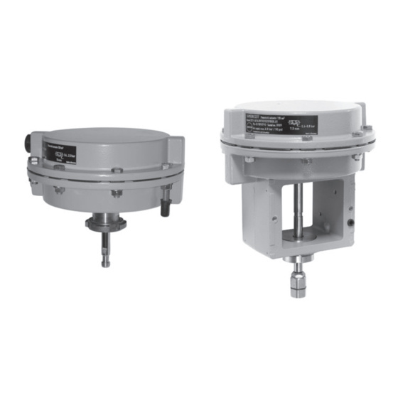
Design and principle of operation 3 Design and principle of operation The Type 3271-5 and Type 3277-5 Actua- The stem connector clamps (A26/27) of Se- tors have an actuator area of 120 cm². The ries 240 Valves connect the actuator stem actuators mainly consist of two diaphragm (A7) with the plug stem of the valve. The ac- cases (A1, A2), a rolling diaphragm (A4) tuator stem (A7) and plug stem (5) of the mi- and internal springs (A10). See Fig. 3-1 and... - Page 14 A133 A5.2 A5.1 A2.1 A2.1 A27.3 A27.1 A26/27 Version for micro-flow valve Fig. 3-2: Type 3277-5 Actuator with 120 cm² actuator area Legend for Fig. 3-1 and Fig. 3-2 Top diaphragm case A5.1 Diaphragm plate A26/27Stem connector clamps Bottom diaphragm case A5.2 Diaphragm plate A27.1 Stem connector nut A2.1...
-
Page 15: Direction Of Action And Signal Pressure Routing
Type 3277-5 (see Fig. 3-2 and Fig. 3-3) Version with handwheel: in the active man- In the Type 3277-5 Actuator, the signal pres- ual mode (the handwheel is not in the neu-... -
Page 16: Actuator Stem Retracts
Marking for signal pressure input A2.8 Seal with filter A2.6 With left attachment A2.9 Signal pressure connection Fig. 3-3: Switchover plate and connecting plate in Type 3277-5 3.2.2 Actuator stem retracts With in- Order no. When the signal pressure is reduced or the 1400-6822... -
Page 17: Versions
Various valve accessories according to handwheel. The handwheel is mounted IEC 60534-6-1 and NAMUR recommenda- on the top diaphragm case and is used tion can be mounted on SAMSON control to adjust the travel manually. valves designed according to the modular principle. See associated valve documenta- 3.5 Technical data... - Page 18 On/off service: –20 to +80 °C Dimensions and weights –4 to +176 °F See Table 3-1 and dimensional drawings on page 3-7 and 3-8. Table 3-1: Dimensions in mm and weights in kg Actuator Type 3271-5 3277-5 Actuator area cm² rated Height – ØD Diameter ØD2 Thread Ød...
- Page 19 Design and principle of operation ØD Dimensional drawings ØD ØD2 Ød ØD2 Type 3271-5 Type 3277-5 Ød EB 8310-1 EN...
- Page 20 Design and principle of operation Dimensional drawings ØD ØD ØD2 ØD2 Ød Ød Type 3271-5 with handwheel Type 3277-5 with travel stop ØD2 ØD2 M14 x 1 M14 x 1 Ød Ød Versions with 7.5 mm travel for Type 3510 Micro-flow Valve EB 8310-1 EN...
-
Page 21: Shipment And On-Site Transport
Shipment and on-site transport 4 Shipment and on-site trans- Î Leave the actuator in its transport con- tainer or on the pallet to transport it on port site. The work described in this section is only to Î Dispose and recycle the packaging in ac- be performed by personnel appropriately cordance with the local regulations. -
Page 22: Transporting The Actuator
Î Observe the storage instructions. tainer or on the pallet to transport it. Î Avoid long storage times. Î Observe the transport instructions. Î Contact SAMSON in case of different storage conditions or longer storage Transport instructions times. − Protect the actuator against external in- fluences (e.g. impact). - Page 23 Shipment and on-site transport − Make sure that the ambient air is free of acids or other corrosive media. − The permissible storage temperature is between –20 and +65 °C. − Do not place any objects on the actuator. Special storage instructions for elastomers Elastomer, e.g.
- Page 24 EB 8310-1 EN...
-
Page 25: Installation
5.2 Mounting the device it has become blocked (e.g. due to seizing up after remaining in the same Depending on the version, SAMSON control position for a long time), release any valves are either delivered with the actuator stored energy in the actuator (e.g. spring already mounted on the valve or the valve compression). -
Page 26: Mounting The Actuator Onto The Valve
Risk of actuator damage due to the use of nector nut (9) on the valve. unsuitable tools. 2. Firmly press the plug together with the Î Only use tools approved by SAMSON plug stem into the seat ring. (u AB 0100). 3. Thread down the lock nut and stem con- nector nut. - Page 27 Installation Bonnet/flange Threaded bushing Stem connector nut Lock nut Travel indicator scale Actuator stem Ring nut A26/27 Stem connector clamps A26/27 Signal pressure connection Fig. 5-1: Type 3271 Pneumatic Actuator on a Series 240 Valve 11. Align the travel indicator scale (84) with 5.
- Page 28 Installation Yoke Plug stem with plug Travel indicator scale Bottom diaphragm case Actuator stem Ring nut A27.1 Stem connector nut A27.2 Bearing sleeve (bottom part of the stem connector) A27.3 Lock nut Fig. 5-2: Type 3277 Pneumatic A27.3 Actuator on a A27.1 Type 3510 Micro-flow A27.2 Valve...
- Page 29 Installation 7. In the "actuator stem extends" version: Anti-rotation fixture already mounted apply a signal pressure that corresponds onto the valve: to the lower bench range value to the ac- Slightly loosen the screws (303) and turn tuator. Turn the stem connector (A27.1 the stem (9) inside the stem connector and A27.2) on the actuator stem until the clamps (301) by a few turns to move it...
- Page 30 Installation Actuator stem Valve bonnet Ring nut Stem A26 Stem connector clamps Clamps Screws Fig. 5-4: Anti-rotation fixture: standard version (left) and special version (right) EB 8310-1 EN...
-
Page 31: Pneumatic Connection
Î Screw the vent plug into the connection on the bottom diaphragm case. − The lower signal pressure range value corresponds to the minimum value of the b) Type 3277-5 bench range or operating range (when the travel range is adapted, see 'Adapt- Operation with positioner (switchover plate) ing the travel range' in the 'Start-up' sec- Î... - Page 32 Right attach- Extends Retracts ment ment ment ment A2.4 Symbol A2.7 With right attachment A2.5 Marking for signal pressure input A2.8 Seal with filter A2.6 With left attachment A2.9 Signal pressure connection Fig. 5-5: Switchover plate and connecting plate in Type 3277-5 EB 8310-1 EN...
-
Page 33: Start-Up
Start-up 6 Start-up WARNING WARNING The work described in this section is only to Risk of personal injury due to exhaust air be performed by personnel appropriately being vented. qualified to carry out such tasks. The actuator is operated with air. As a result, air is vented during operation. Î... -
Page 34: Adapting The Travel Range
This may apply, for exam- Actuator stem extends ple, to the configuration ID or the symbol af- When a SAMSON valve is combined with ter reversal of the direction of action. an oversized actuator (i.e. the rated actuator Î Immediately renew any nameplates or... -
Page 35: Travel Stop
Start-up 6.2 Travel stop 4. Attach the cover (A73) and retighten the lock nut (A70). In the version with travel stop, the maximum and minimum actuator travel can be limited 6.2.2 Top travel stop (maximum (see Fig. 6-1). travel) 6.2.1 Bottom travel stop (min- 1. -
Page 36: Extending The Actuator Stem Manually
Start-up 6.3.1 Extending the actuator To change from manual to automatic opera- tion, put the handwheel into the neutral posi- stem manually tion by aligning the dot on the stem connec- tor (A51) within the window on the plastic 1. Turn the handwheel clockwise until the cover with the horizontal marking on the bottom stop position is reached. -
Page 37: Operation
Î Wear eye and hearing protection when labels with incorrect or outdated infor- working near the actuator. mation. Î Add any new values to the nameplate. If necessary, contact SAMSON to obtain a WARNING WARNING new nameplate. Crush hazard arising from the moving actuator stem. -
Page 38: Manual Mode (Versions With Handwheel Only)
Operation 7.4 Additional notes con- Actuator stem retracts cerning operation With fail-safe action "actuator stem retracts", the permissible supply pressure must not ex- Î Label actuators with reduced supply ceed the upper bench range value by more pressure with a sticker ("Max. supply than 3 bar: pressure limited to ... -
Page 39: Malfunctions
Malfunctions 8 Malfunctions Read hazard statements, warnings and caution notes in the 'Safety instructions and mea- sures' section. 8.1 Troubleshooting Malfunction Possible reasons Recommended action Actuator stem does not Actuator is blocked. Check attachment. move on demand. Remove the blockage. WARNING! A blocked actuator (e.g. due to seizing up after remaining in the same position for a long time) can suddenly start to move uncontrollably. -
Page 40: Emergency Action
Malfunctions 8.2 Emergency action Plant operators are responsible for emergen- cy action to be taken in the plant. EB 8310-1 EN... -
Page 41: Servicing And Conversion
Servicing and conversion 9 Servicing and conversion WARNING WARNING The work described in this section is only to Risk of personal injury due to exhaust air be performed by personnel appropriately being vented. qualified to carry out such tasks. The actuator is operated with air. As a result, air is vented during operation. -
Page 42: Periodic Testing
NOTICE Risk of actuator damage due to the use of unsuitable tools. 9.2 Preparation for servicing Î Only use tools approved by SAMSON or conversion work (u AB 0100). 1. Lay out the necessary material and tools to have them ready for the intended NOTICE work. -
Page 43: Mounting The Actuator On The Valve After Service Or Conversion Work
Servicing and conversion 9.4 Service work Note To remove an actuator with "stem extends" See Fig. 9-1 fail-safe action and/or with preloaded 9.4.1 Replacing the dia- springs, a certain signal pressure must be applied to the actuator (see the 'Removal' phragm section). Afterwards, the signal pressure must be removed and the air supply discon- nected again and locked. - Page 44 Servicing and conversion A15 A9 Fig. 9-1: Type 3271-5 and Type 3277-5 Pneumatic Actuators A5.1 A5.2 Type 3271-5 A20/21 A2.1 Type 3277-5 A133 Top diaphragm case Actuator stem Radial shaft seal Bottom diaphragm case Ring nut Wiper ring A2.1 Switchover/connecting Hex nut Dry bearing plate for signal pressure...
-
Page 45: Replacing The Actuator Stem Seals
Servicing and conversion 6. Check the sealing element of the collar 4. Remove the diaphragm plate (A5.1), di- nut (A15). If necessary, renew it (order aphragm (A4) and diaphragm plate no. 8353-0533). (A5.2) from the actuator stem (A7). 7. Apply a suitable lubricant to the actuator 5. - Page 46 Servicing and conversion a) Actuator stem extends b) Actuator stem retracts 1. Lift off the top diaphragm case (A1) and 1. Lift off the top diaphragm case (A1). remove springs (A10). 2. Pull the actuator stem (A7) together with 2. Pull the actuator stem (A7) together with the diaphragm plate (A5.1), diaphragm the diaphragm plate (A5.1), diaphragm (A4) and diaphragm plate (A5.2) out of...
-
Page 47: Conversion Work
Servicing and conversion (A4) and diaphragm plate (A5.2) out of Radial shaft seal the bottom diaphragm case (A2). 3. Unscrew the collar nut (A15). Seal lip NOTICE Malfunction due to loosened nut. The nut (A9) on the actuator stem serves to Wiper ring adjust the dimension a. - Page 48 Table 9-1. bottom connection (S). 5. Remove the diaphragm plate (A51), dia- Type 3277-5: connect the signal pres- phragm (A4) and diaphragm plate sure as described in 'Pneumatic connec- (A5.2) from the actuator stem (A7) and tion' in the 'Installation' section.
-
Page 49: Determining Dimension A
100.75 Type 3271-5 for micro-flow valve 3277-5 188.5 3277-5 185.5 Type 3277-5 for micro-flow 158.5 valve 9.7 Ordering spare parts and operating supplies Contact your nearest SAMSON subsidiary or SAMSON's After-sales Service for infor- mation on spare parts, lubricants and tools. EB 8310-1 EN... - Page 50 9-10 EB 8310-1 EN...
-
Page 51: Decommissioning
Decommissioning 10 Decommissioning WARNING WARNING The work described in this section is only to Risk of personal injury due to exhaust air be performed by personnel appropriately being vented. qualified to carry out such tasks. The actuator is operated with air. As a result, air is vented during operation. Î... - Page 52 10-2 EB 8310-1 EN...
-
Page 53: Removal
Removal 11 Removal WARNING WARNING The work described in this section is only to Risk of personal injury due to exhaust air be performed by personnel appropriately being vented. qualified to carry out such tasks. The actuator is operated with air. As a result, air is vented during operation. Î... -
Page 54: Removing The Actuator From The Valve
Removal 11.1 Removing the actuator 4. Lift the actuator off the valve. from the valve 5. Fasten the lock nut (10) and stem con- nector nut (9) on the valve. a) Series 240 Valves 6. Fasten ring nut (A8) on the actuator. 1. - Page 55 Removal b) Type 3510 Micro-flow Valve nector nut (A27.1) and bearing sleeve (A27.2) stationary and unscrew them. 1. Loosen the lock nut (A27.3). 3. Loosen the ring nut (A8). 2. In the "actuator stem extends" version: 4. Lift the actuator off the valve. to retract the actuator stem, apply a sig- 5.
-
Page 56: Relieving The Spring Compression In The Actuator
Removal 11.2 Relieving the spring com- pression in the actuator The long clamping bolts with long clamping nuts and the short bolts with short nuts are arranged evenly around the circumference of the actuator housing to fasten the top and bottom diaphragm cases together. -
Page 57: Repairs
Î Do not perform any repair work on your outside of your shipment so that the own. documents are clearly visible. Î Contact SAMSON's After-sales Service 4. Send the shipment to the address given for repair work. on the RMA. - Page 58 12-2 EB 8310-1 EN...
-
Page 59: Disposal
Disposal 13 Disposal Î Observe local, national and internation- al refuse regulations. Î Do not dispose of components, lubricants and hazardous substances together with your household waste. EB 8310-1 EN 13-1... - Page 60 13-2 EB 8310-1 EN...
-
Page 61: Certificates
Certificates 14 Certificates The declarations of incorporation in compli- ance with Machinery Directive 2006/42/EC and the Directive 2008 No. 1597 Supply of Machinery (Safety) Regulations 2008 for Type 3271-5 and Type 3277-5 Pneumatic Actuators with 120 cm² actuator areas are provided on the following pages. The certificates shown were up to date at the time of publishing. The latest certificates can be found on our website: − u www.samsongroup.com > Products & Applications > Product selector >... - Page 62 14-2 EB 8310-1 EN...
- Page 63 Peter Scheermesser Director Director Product Management Product Life Cycle Management and ETO Development for Valves and Actuators Revision 00 Classification: Public · SAMSON AKTIENGESELLSCHAFT · Weismuellerstrasse 3 · 60314 Frankfurt am Main, Germany Page 1 of 1 EB 8310-1 EN 14-3...
- Page 64 14-4 EB 8310-1 EN...
-
Page 65: Annex
Annex 15 Annex 15.1 Tightening torques, lubricants and tools u AB 0100 for tools, tightening torques and lubricants 15.2 Spare parts Top diaphragm case Axial needle seal Bottom diaphragm case Shim Switchover or connecting plate Radial shaft seal 1) Diaphragm Dry bearing Diaphragm plate (two-piece) Handwheel Actuator stem Washer Ring nut Diaphragm plate (two-piece) - Page 66 160* 26/27 Type 3271-5 Actuator 15-2 EB 8310-1 EN...
- Page 67 27.3 160* 27.1 Micro-flow valve version 26/27 160* Type 3277-5 Actuator EB 8310-1 EN 15-3...
-
Page 68: After-Sales Service
Addresses of SAMSON AG and its subsid- Importer iaries SAMSON Controls Ltd The addresses of SAMSON AG, its subsid- Perrywood Business Park iaries, representatives and service facilities Honeycrock Lane worldwide can be found on our website Redhill, Surry RH1 5JQ (www.samsongroup.com) or in all SAMSON Phone: +44 1737 766391... - Page 70 EB 8310-1 EN SAMSON AKTIENGESELLSCHAFT Weismüllerstraße 3 · 60314 Frankfurt am Main, Germany Phone: +49 69 4009-0 · Fax: +49 69 4009-1507 [email protected] · www.samsongroup.com...