
Related Manuals for Samson EB 8061 EN


Summary of Contents for Samson EB 8061 EN
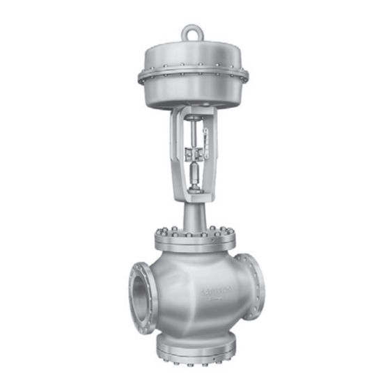
- Page 1 EB 8061 EN Translation of original instructions Type 3254 Valve with Type 3271 Actuator Type 3254 Valve · ANSI version In combination with an actuator, e.g. a Type 3271 or Type 3277 Pneumatic Actuator Edition January 2021...
- Page 2 Note on these mounting and operating instructions These mounting and operating instructions assist you in mounting and operating the device safely. The instructions are binding for handling SAMSON devices. The images shown in these instructions are for illustration purposes only. The actual product may vary.
-
Page 3: Table Of Contents
5.3.2 Mounting the actuator onto the valve ............5-13 5.3.3 Installing the valve into the pipeline ............5-15 Testing the installed valve ................5-16 5.4.1 Leak test ....................5-17 5.4.2 Travel motion ....................5-17 5.4.3 Fail-safe position ..................5-18 5.4.4 Pressure test ....................5-18 EB 8061 EN... - Page 4 Removal ....................11-1 11.1 Removing the valve from the pipeline ............11-2 11.2 Removing the actuator from the valve ............11-2 Repairs ....................12-1 12.1 Returning devices to SAMSON ..............12-1 Disposal ....................13-1 Certificates ....................14-1 Annex......................15-1 15.1 Tightening torques, lubricants and tools ............15-1 15.2 Spare parts ....................15-2 15.3...
-
Page 5: Safety Instructions And Measures
SAMSON. SAMSON does not assume any liability for damage resulting from the failure to use the de- vice for its intended purpose or for damage caused by external forces or any other external factors. - Page 6 (see associated actuator documentation). When the valve is combined with a SAMSON Type 3271 or Type 3277 Pneumatic Actuator, the valve moves to a certain fail- safe position (see the 'Design and principle of operation' section) upon supply air or control signal failure.
- Page 7 Start-up and shutdown procedures fall within the scope of the operator's duties and, as such, are not part of these mounting and operating instructions. SAMSON is unable to make any statements about these procedures since the operative details (e.g. differential pressures and temperatures) vary in each individual case and are only known to the operator.
-
Page 8: Notes On Possible Severe Personal Injury
− u AB 0100 for tools and tightening torques − Manual u H 02: Appropriate Machinery Components for SAMSON Pneumatic Control Valves with a Declaration of Conformity of Final Machinery − When a substance is used in the device, which is listed as being a substance of very high... -
Page 9: Notes On Possible Personal Injury
Î Before unblocking the actuator and plug stem after they have become blocked (e.g. due to seizing up after remaining in the same position for a long time), release any stored energy in the actuator (e.g. spring compression). See associated actuator documentation. EB 8061 EN... - Page 10 Risk of personal injury due to preloaded springs. Valves in combination with pneumatic actuators with preloaded springs are under ten- sion. These control valves with SAMSON pneumatic actuators can be identified by the long bolts protruding from the bottom of the actuator.
-
Page 11: Notes On Possible Property Damage
Risk of valve damage due to the use of unsuitable tools. Certain tools are required to work on the valve. Î Only use tools approved by SAMSON (u AB 0100). Risk of valve damage due to the use of unsuitable lubricants. The lubricants to be used depend on the valve material. Unsuitable lubricants may cor- rode and damage surfaces. -
Page 12: Notes On The Use Of An Rfid Tag
There is a risk of injury to hands or fingers through the stroking movement of the actuator and plug stem if they are inserted into the yoke while the air supply is con- nected to the actuator. EB 8061 EN... -
Page 13: Markings On The Device
13 Seat code (trim material): on request L1: liquids 14 Pressure balancing: Fluid group 1 = hazardous DIN: D · ANSI/JIS: B Fluid group 2 = other Version: I/II/III: Category 1 to 3 M: mixing valve · V: flow-diverting valve 21 Serial number 22 NE 53 (NAMUR Recommendation) EB 8061 EN... -
Page 14: Actuator Nameplate
(see the 'Design and principle of opera- material is used. Additionally, a seat code is tion' section). used to identify the trim material. This seat code is specified on the nameplate. EB 8061 EN... -
Page 15: Design And Principle Of Operation
The Type 3254 Valve is a single-seated jammed. globe valve. This valve is preferably com- bined with a SAMSON Type 3271 or 3.1 Fail-safe action Type 3277 Pneumatic Actuator (see Fig. 3-1). It can also be combined with other The fail-safe position of the control valve up- actuators. - Page 16 Packing Body gasket Travel indicator scale Castellated nut Flange Diaphragm Actuator stem Ring nut Spring Vent plug A26/27 Stem connector clamps Signal pressure connection Fig. 3-1: Type 3254 Valve with Type 3271 Pneumatic Actuator (left) and Type 3277 Pneumatic Actuator (right) EB 8061 EN...
-
Page 17: Versions
Actuators Insulation In these instructions, the preferable combina- tion with a SAMSON Type 3271 or Control valves can be insulated to reduce Type 3277 Pneumatic Actuator is described. heat energy transfer. The pneumatic actuator (with or without... -
Page 18: Valve Accessories
Note More information is available in Data Sheet Noise emissions u T 8061. SAMSON is unable to make general state- ments about noise emissions. The noise emis- Conformity sions depend on the valve version, plant fa- The Type 3254 Valve bears both the CE and cilities and process medium. - Page 19 29.00 Class 900 ing ends) 18.50 21.50 27.75 32.75 Class 1500 22.75 26.50 36.00 40.25 Class 2500 1022 8.74 9.53 12.37 15.24 Class 150 to 8.74 9.53 12.37 15.24 Height H4 Class 900 11.34 13.7 17.56 22.44 Class 1500 to 2500 EB 8061 EN...
- Page 20 18.90 19.80 19.80 2800 cm² 18.90 18.90 19.80 19.80 2x2800 cm² 6.89 8.15 11.34 15.35 Class 150 8.74 9.80 13.31 15.35 Class 300 to 8.74 9.80 13.31 15.35 Class 900 11.02 12.24 17.40 20.87 Class 1500 11.02 13.11 17.72 Class 2500 On request EB 8061 EN...
- Page 21 On request On request On request On request to 2500 350 cm² – 355 cm² – 16.46 700 cm² – 16.46 H8 for 750 cm² actuator 1000 cm² On request 1400- On request On request 60 cm² 19.80 25.59 25.59 25.59 1400- 120 cm² 4) EB 8061 EN...
- Page 22 NPS 10 in Class 150 to 300: 442 mm/17.40 in NPS 10 in Class 600 to 900: 519 mm/20.43 in Class 1500 H8 = 650 mm with 250 mm seat bore Face-to-face dimensions according to SAMSON standard Dimensional drawings Standard version Version with insulating section or bellows seal EB 8061 EN...
- Page 23 Table 3-2: Dimensions and weights for Type 3254 Valve · Version with insulating section Table 3-2.1: Valve size NPS 3 to 8 (DN 80 to 200) Valve size 19.37 20.16 26.18 37.28 Class 150 to 19.37 20.16 26.18 37.28 Height H4 Class 900 21.5 23.54 31.10 42.13 Class 1500 to 2500 1070 EB 8061 EN...
- Page 24 1973 2271 2476 4350 Class 300 1030 1123 1973 Weight On request 2641 3512 6268 without Class 600 actuator 1198 1593 2843 3201 3997 6929 Class 900 1452 1813 3143 Class 1500 to Class 1500 On request 2500 On request 3-10 EB 8061 EN...
- Page 25 1.18 to 2.36 62.24 Class 600 to 900 – 30 to 60 1581 4.72 Class 600 – 1146 Class 150 Weight 1146 Class 300 valve with 1521 bellows Class 600 seal 1609 (without Class 900 actua- tor) for Class 1500 and On request 2500 EB 8061 EN 3-11...
- Page 26 Class 300 1075 1168 2020 with 2745 3616 6371 bellows On re- Class 600 seal quest 1245 1640 2890 (without 3307 4101 7033 Class 900 actuator) 1500 1860 3190 Class 1500 On re- On request and 2500 quest 3-12 EB 8061 EN...
- Page 27 Design and principle of operation Note The associated actuator documentation applies to actuators, e.g. SAMSON pneumatic actu- ators: u T 8310-1 for Type 3271 or Type 3277 Pneumatic Actuators up to 750 cm² actuator area u T 8310-2 for Type 3271 Actuator with 1000 cm² actuator area and larger u T 8310-3 for Type 3271 Actuator with 1400-60 cm²...
- Page 28 3-14 EB 8061 EN...
-
Page 29: Shipment And On-Site Transport
2. Check the shipment for transportation Î Stay clear of suspended or moving damage. Report any damage to loads. SAMSON and the forwarding agent Î Close off and secure the transport paths. (refer to delivery note). 3. Determine the weight and dimensions of... -
Page 30: Transporting The Valve
Risk of personal injury due to the control A swivel hoist can be screwed into valve tipping over. SAMSON actuators with a female thread on Î Observe the valve's center of gravity. the top diaphragm case in place of the Î... -
Page 31: Lifting The Valve
− Make sure the slings can be removed from the valve once it has been installed into the pipeline. − Prevent the control valve from tilting or tipping over. Fig. 4-1: Lifting points on the control valve: with flanges (left) and with welding ends (right) EB 8061 EN... - Page 32 5. Install the valve into the pipeline (see the 'Installation' section). 6. After installation in the pipeline, check whether the flanges are bolted tight and the valve in the pipeline holds. 7. Remove slings. EB 8061 EN...
-
Page 33: Storing The Valve
Elastomer, e.g. actuator diaphragm Î Avoid long storage times. − To keep elastomers in shape and to pre- Î Contact SAMSON in case of different vent cracking, do not bend them or hang storage conditions or longer storage them up. - Page 34 EB 8061 EN...
-
Page 35: Installation
–10 °C (14 °F) Plant operators must ensure that, after instal- lation of the device, the operating personnel Î Contact SAMSON if the mounting posi- can perform all necessary work safely and tion is not as specified above. easily access the device from the work posi- Support or suspension tion. -
Page 36: Preparation For Installation
− The valve data on the nameplate (type make sure that they are easily accessible designation, valve size, material, pres- and can be operated safely from the sure rating and temperature range) work position. match the plant conditions (size and EB 8061 EN... -
Page 37: Mounting The Device
NOTICE work. Risk of valve damage due to the use of Î Flush the pipelines. unsuitable tools. Î Only use tools approved by SAMSON Note (u AB 0100). The plant operator is responsible for clean- ing the pipelines in the plant. Î For steam applications, dry the pipelines. -
Page 38: Mounting The External Anti-Rotation Fixture
The valve must NOTICE be closed beforehand. Impaired functioning due to incorrectly ap- For SAMSON Type 3271 and Type 3277 plied lubricant. Actuators with Type 3273 Hand-operated Î Do not apply any lubricant to the threads Actuator, observe the mounting and operat- of the clamps (301) or the plug stem. - Page 39 14. Extend the actuator stem again and mount the stem connector clamps. Plug stem Legend Yoke Screws Hanger Travel indicator scale Screws Castellated nut Warning label Ball bearing Fig. 5-1: Overview of yoke assembly with travel indicator scale in the standard version EB 8061 EN...
- Page 40 Installation Plug stem Legend Stem Lubricant Gleitmo 1763 V Clamps Screws Washers Sliding washers Fig. 5-2: Overview of anti-rotation fixture assembly in the standard version EB 8061 EN...
- Page 41 (301) or the plug stem. 6. Position the clamps (301) and stem (9) on the plug stem according to Table 5-4 and tighten screws (303) and washers (304) by hand. 7. Mount the actuator. See section 5.3.2. EB 8061 EN...
- Page 42 Installation Legend Yoke Screws Hanger Plug stem Travel indicator scale Castellated nut Warning label Holder Screws Washers Fig. 5-3: Overview of yoke assembly with travel indicator scale in the special version EB 8061 EN...
- Page 43 Installation Plug stem Legend Stem Lubricant Gleitmo 1763 V Clamps Screws Washers Sliding washers Fig. 5-4: Overview of anti-rotation fixture assembly in the special version EB 8061 EN...
- Page 44 NPS 3 to 4 · Special version 3.75 – – 22.5 118.5 67.5 34.5 103.5 82.5 34.5 1000 1400-60 – – 1400-120 2800 NPS 6 · Standard version 263.5 67.5 22.5 263.5 67.5 248.5 82.5 1000 1400-60 87.5 1400-120 2800 5600 5-10 EB 8061 EN...
- Page 45 NPS 10, seat bore 250 and NPS 12 to 20 · Standard version 1000 1400-60 1400-120 = 115 1) = 86 2) 2800 5600 = 86 2) FA = Actuator stem extends (fail-close) FE = Actuator stem retracts (fail-open) EB 8061 EN 5-11...
- Page 46 Installation Ball bearings (standard version only) Fig. 5-5: Dimensional drawing with mounting dimensions for Types 3271 and 3277 Pneumatic Actuators 5-12 EB 8061 EN...
-
Page 47: Mounting The Actuator Onto The Valve
Installation 5.3.2 Mounting the actuator Depending on the version, SAMSON control valves are either delivered with the actuator onto the valve already mounted on the valve or the valve and actuator are delivered separately. When WARNING delivered separately, the valve and actuator Risk of personal injury due to preloaded must be assembled together on site. - Page 48 To do so, align '0' on the travel indicator scale with the tip of the stem connector clamp (see Fig. 5-5). 1. Move the valve to the closed position. 2. Loosen the screws on the travel indicator scale. 5-14 EB 8061 EN...
-
Page 49: Installing The Valve Into The Pipeline
2. Prepare the relevant section of the pipe- line for installing the valve. 3. Remove the protective caps from the valve ports before installing the valve. EB 8061 EN 5-15... -
Page 50: Testing The Installed Valve
Additionally, a loud noise may briefly occur through the sudden venting of the pneumatic actuator or pneumatic valve accessories not fitted with noise-reducing fittings. Both can damage hearing. 5-16 EB 8061 EN... -
Page 51: Leak Test
5.4.2 Travel motion velocities can damage the valve. 3. Open the valve. The movement of the actuator stem must be linear and smooth. 4. Apply the required test pressure. EB 8061 EN 5-17... -
Page 52: Fail-Safe Position
During the pressure test, make sure the fol- lowing conditions are met: − Retract the plug stem to open the valve. − Observe the maximum permissible pres- sure for both the valve and plant. 5-18 EB 8061 EN... -
Page 53: Start-Up
Î Wear eye protection when working in may occur through the sudden venting of the close proximity to the control valve. pneumatic actuator (see 'Fail-safe position') or pneumatic valve accessories not fitted with noise-reducing fittings. Both can damage hearing. EB 8061 EN... - Page 54 2. Slowly open the shut-off valves in the pipeline. Slowly opening these valves prevents a sudden surge in pressure and high flow velocities which can damage the valve. 3. Check the valve to ensure it functions properly. EB 8061 EN...
-
Page 55: Operation
Î Wear eye protection when working in occur through the sudden venting of the close proximity to the control valve. pneumatic actuator or pneumatic valve ac- cessories not fitted with noise-reducing fit- tings. Both can damage hearing. EB 8061 EN... -
Page 56: Normal Operation
The handwheel of valves with actuators fitted with a handwheel must be in the neutral po- sition during normal operation. 7.2 Manual operation Valves with actuators fitted with a handwheel can be manually closed or opened in case of supply air failure. EB 8061 EN... -
Page 57: Malfunctions
Shut off the section of the pipeline and flush the closed valve (seat particles deposited valve. leakage) between the seat and plug. Valve trim, particularly Replace seat and plug (see the 'Servicing' section) with soft seat, is worn. or contact our after-sales service. EB 8061 EN... -
Page 58: Emergency Action
Putting the valve back into operation after 1. Close the shut-off valves upstream and a malfunction downstream of the control valve to stop See the 'Start-up' section. the process medium from flowing through the valve. 2. Perform troubleshooting (see sec- tion 8.1). EB 8061 EN... -
Page 59: Servicing
Î Do not insert hands or finger into the components and pipeline. yoke while the air supply is connected to Valve components and the pipeline may be- the actuator. come very hot or cold. Risk of burn injuries. EB 8061 EN... - Page 60 Risk of valve damage due to the use of WARNING unsuitable tools. Risk of personal injury due to preloaded Î Only use tools approved by SAMSON springs. (u AB 0100). Actuators with preloaded springs are under tension. They can be identified by the long...
-
Page 61: Periodic Testing
Servicing 9.1 Periodic testing Note The control valve was checked by SAMSON Depending on the operating conditions, before it left the factory. check the valve at certain intervals to prevent − Certain test results certified by SAMSON possible failure before it can occur. Plant op-... - Page 62 Put the control valve out of operation (see the position by briefly interrupting the air 'Decommissioning' section). Identify the cause for the supply. malfunction and rectify it (see the 'Troubleshooting' section). See the 'Markings on the device' section EB 8061 EN...
- Page 63 Servicing Fig. 9-1: Standard version of Type 3254 with Type 3271 Actuator (left) and Type 3254 in version with insulating section (right) EB 8061 EN...
-
Page 64: Preparing The Valve For Service Work
The following service work can be per- anti-rotation fixture on the plug stem. formed after preparation is completed: − Replace the top gasket as described in 1. Lay out the necessary material and tools section 9.4.1. to have them ready for the service work. EB 8061 EN... -
Page 65: Installing The Valve After Service Work
'Installation' section). let. Version with perforated plug: place the bonnet (2) onto the valve body, making sure that the hole of the plug that releas- es the flow first faces toward the valve outlet. EB 8061 EN... -
Page 66: Replacing The Bottom Gasket
5. Insert a new gasket (17) into the flange. ing the actuator onto the valve' in the 'In- 6. Place the flange (100) onto the body. stallation' section. Make sure that the plug stem (5) is prop- erly seated in the guide. EB 8061 EN... -
Page 67: Replacing The Packing
(14). Tighten the nuts gradual- 4. Unscrew the stem connector nut (9) and ly in a crisscross pattern. Observe tight- lock nut (10) from the plug stem. ening torques. 5. Unscrew the threaded bushing (8). EB 8061 EN... - Page 68 (PTFE)’, steps 13 to 16. 2. Carefully slide the packing parts over the plug stem into the packing chamber us- ing a suitable tool. Observe the proper sequence (see Fig. 9-3). 3. Slide the seals (15.2) over the plug stem. 9-10 EB 8061 EN...
- Page 69 4. Unscrew the stem connector nut (9) and 1. Unscrew the castellated nut (92) and lift lock nut (10) from the plug stem. the yoke (3) off the insulating section (21). 5. Unscrew the threaded bushing (8). EB 8061 EN 9-11...
- Page 70 Legend for Fig. 9-4 Body Stud bolt Bonnet Yoke Packing Seat Body gasket Plug (with plug stem) Insulating section Guide bushing Castellated nut Threaded bushing (packing nut) Expansion sleeve (for Class 150 to 2500) Stem connector nut Flange Lock nut 9-12 EB 8061 EN...
- Page 71 Servicing Fig. 9-4: Standard version of Type 3254 with Type 3271 Actuator (left) and Type 3254 in version with insulating section (right) EB 8061 EN 9-13...
-
Page 72: Replacing The Seat And Plug
9. Make sure that the top guide bushing (7) versions, contact our after-sales service. is not damaged. If necessary, replace the guide bushing using a suitable tool. 10. Unscrew the seat (4) using a suitable tool. 9-14 EB 8061 EN... - Page 73 10. Unscrew the seat (4) using a suitable body nuts (14). Tighten the nuts gradual- tool. ly in a crisscross pattern. Observe tight- 11. Apply a suitable lubricant to the thread ening torques. and the sealing cone of the new seat. EB 8061 EN 9-15...
-
Page 74: Ordering Spare Parts And Operating Supplies
15. Place the insulating section (21) together Contact your nearest SAMSON subsidiary with the plug stem and plug (5) onto the or SAMSON's After-sales Service for infor- body (1). mation on spare parts, lubricants and tools. Version with V-port plug: place the insu-... -
Page 75: Decommissioning
Î Do not impede the movement of the actuator and plug stem by inserting objects into the yoke. Î Before unblocking the actuator and plug stem after they have become blocked EB 8061 EN 10-1... - Page 76 To decommission the control valve for service work or to remove it from the pipeline, pro- ceed as follows: 1. Close the shut-off valves upstream and downstream of the control valve to stop the process medium from flowing through the valve. 10-2 EB 8061 EN...
-
Page 77: Removal
Î Do not loosen the screws (303) of the (e.g. spring compression). See anti-rotation fixture while the force associated actuator documentation. generated by the supply air and/or the EB 8061 EN 11-1... -
Page 78: Removing The Valve From The Pipeline
Version with welding ends 1. Support the valve to hold it in place when separated from the pipeline (see the 'Shipment and on-site transport' sec- tion). 2. Cut the pipeline in front of the weld seam. 11-2 EB 8061 EN... -
Page 79: Repairs
Î Do not perform any repair work on your outside of your shipment so that the own. documents are clearly visible. Î Contact SAMSON's After-sales Service 4. Send the shipment to the address given for repair work. on the RMA. - Page 80 12-2 EB 8061 EN...
-
Page 81: Disposal
Disposal 13 Disposal Î Observe local, national and internation- al refuse regulations. Î Do not dispose of components, lubricants and hazardous substances together with your household waste. EB 8061 EN 13-1... - Page 82 13-2 EB 8061 EN...
-
Page 83: Certificates
The certificates shown were up to date at the time of publishing. The latest certificates can be found on our website: u www.samsongroup.com > Products & Applications > Product selector > Valves > 3254 Other optional certificates are available on request. EB 8061 EN 14-1... - Page 84 14-2 EB 8061 EN...
- Page 85 EB 8061 EN 14-3...
- Page 86 14-4 EB 8061 EN...
-
Page 87: Annex
Annex 15 Annex 15.1 Tightening torques, lubri- cants and tools u AB 0100 for tools, tightening torques and lubricants EB 8061 EN 15-1... -
Page 88: Spare Parts
Version with balanced valve plug 34 Bolt Version with flow divider 37 Plug stem with metal bellows With NPS 3 to 6 only 39 Gasket 42 Screw plug with seal 44 Ring/ring nut 1) 45 Packing ring 1) 15-2 EB 8061 EN... - Page 89 EB 8061 EN 15-3...
-
Page 90: After-Sales Service
You can reach our after-sales service at [email protected]. Addresses of SAMSON AG and its subsid- iaries The addresses of SAMSON AG, its subsid- iaries, representatives and service facilities worldwide can be found on our website (www.samsongroup.com) or in all SAMSON product catalogs. - Page 92 EB 8061 EN SAMSON AKTIENGESELLSCHAFT Weismüllerstraße 3 · 60314 Frankfurt am Main, Germany Phone: +49 69 4009-0 · Fax: +49 69 4009-1507 [email protected] · www.samsongroup.com...