
Related Manuals for Daikin RXTA-N


Summary of Contents for Daikin RXTA-N
- Page 1 Installer reference guide R32 split series RXTM30N2V1B RXTA30N2V1B RXTM40N2V1B RXTP25N2V1B9 RXTP35N2V1B9 RXTP25N2V1B8 RXTP35N2V1B8 ARXTP25N2V1B ARXTP35N2V1B...
-
Page 2: Table Of Contents
Table of contents Table of contents 1 About the documentation About this document ..............................2 General safety precautions About the documentation .............................. 2.1.1 Meaning of warnings and symbols ........................ For the installer ................................2.2.1 General ................................2.2.2 Installation site ............................... 2.2.3 Refrigerant —... - Page 3 Table of contents To charge additional refrigerant............................. 45 To fix the fluorinated greenhouse gases label ....................... 46 9 Electrical installation About connecting the electrical wiring .......................... 47 9.1.1 Precautions when connecting the electrical wiring..................47 9.1.2 Guidelines when connecting the electrical wiring..................49 9.1.3 Specifications of standard wiring components....................
-
Page 4: About The Documentation
The original documentation is written in English. All other languages are translations. Technical engineering data ▪ A subset of the latest technical data is available on the regional Daikin website (publicly accessible). ▪ The full set of latest technical data is available on the Daikin Business Portal (authentication required). -
Page 5: General Safety Precautions
General safety precautions 2 General safety precautions 2.1 About the documentation ▪ The original documentation is written in English. All other languages are translations. ▪ The precautions described in this document cover very important topics, follow them carefully. ▪ The installation of the system, and all activities described in the installation manual and in the installer reference guide MUST be performed by an authorised installer. -
Page 6: For The Installer
Improper installation or attachment of equipment or accessories could result in electrical shock, short-circuit, leaks, fire or other damage to the equipment. Only use accessories, optional equipment and spare parts made or approved by Daikin. WARNING Make sure installation, testing and applied materials comply with applicable legislation (on top of the instructions described in the Daikin documentation). -
Page 7: Installation Site
General safety precautions WARNING Provide adequate measures to prevent that the unit can be used as a shelter by small animals. Small animals that make contact with electrical parts can cause malfunctions, smoke or fire. CAUTION Do NOT touch the air inlet or aluminium fins of the unit. CAUTION ▪... - Page 8 WARNING Make sure installation, servicing, maintenance and repair comply with instructions from Daikin and with applicable legislation (for example national gas regulation) and are executed only by authorised persons. WARNING If one or more rooms are connected to the unit using a duct system, make sure: ▪...
- Page 9 General safety precautions NOTICE ▪ Do NOT re-use joints which have been used already. ▪ Joints made in installation between parts of refrigerant system shall be accessible for maintenance purposes. Installation space requirements WARNING If appliances contain R32 refrigerant, the floor area of the room in which the appliances are installed, operated and stored MUST be larger than the minimum floor area defined in table below A (m ).
- Page 10 General safety precautions m (kg) 1.843 7.956 Ceiling-mounted Wall-mounted Floor-standing unit unit unit m (kg) m (kg) m (kg) ≤1.842 — ≤1.842 — ≤1.842 — 1.843 3.64 1.843 4.45 1.843 28.9 3.95 4.83 34.0 5.31 41.2 4.34 4.74 5.79 49.0 5.13 6.39 57.5...
-
Page 11: Refrigerant - In Case Of R410A Or R32
General safety precautions (b) Wall-mounted unit (= Wall-mounted unit) (c) Floor-standing unit (= Floor-standing unit) 2.2.3 Refrigerant — in case of R410A or R32 If applicable. See the installation manual or installer reference guide of your application for more information. NOTICE Make sure refrigerant piping installation complies with applicable legislation. -
Page 12: Brine
General safety precautions WARNING Make sure there is no oxygen in the system. Refrigerant may only be charged after performing the leak test and the vacuum drying. Possible consequence: Self-combustion and explosion of the compressor because of oxygen going into the operating compressor. ▪... -
Page 13: Water
General safety precautions WARNING The ambient temperature inside the unit can get much higher than that of the room, e.g. 70°C. In case of a brine leak, hot parts inside the unit can create a hazardous situation. WARNING The use and installation of the application MUST comply with the safety and environmental precautions specified in the applicable legislation. - Page 14 General safety precautions WARNING ▪ ONLY use copper wires. ▪ Make sure the field wiring complies with the applicable legislation. ▪ All field wiring MUST be performed in accordance with the wiring diagram supplied with the product. ▪ NEVER squeeze bundled cables and make sure they do NOT come in contact with the piping and sharp edges.
- Page 15 General safety precautions NOTICE Only applicable if the power supply is three‑phase, and the compressor has an ON/ OFF starting method. If there exists the possibility of reversed phase after a momentary black out and the power goes on and off while the product is operating, attach a reversed phase protection circuit locally.
-
Page 16: Specific Installer Safety Instructions
Specific installer safety instructions 3 Specific installer safety instructions Always observe the following safety instructions and regulations. WARNING: FLAMMABLE MATERIAL The refrigerant inside this unit is mildly flammable. Unit installation (see "6 Unit installation" [ 25]) WARNING Installation shall be done by an installer, the choice of materials and installation shall comply with the applicable legislation. - Page 17 Specific installer safety instructions CAUTION ▪ Use the flare nut fixed to the unit. ▪ To prevent gas leakage, apply refrigeration oil only to the inside of the flare. Use refrigeration oil for R32. ▪ Do NOT reuse joints. CAUTION ▪...
- Page 18 Specific installer safety instructions CAUTION To avoid compressor breakdown, do NOT charge more than the specified amount of refrigerant. WARNING NEVER directly touch any accidental leaking refrigerant. This could result in severe wounds caused by frostbite. Electrical installation (see "9 Electrical installation" [ 47]) WARNING...
- Page 19 Specific installer safety instructions WARNING ▪ Do NOT use locally purchased electrical parts inside the product. ▪ Do NOT branch the power supply for the drain pump, etc. from the terminal block. This could result in electrical shock or fire. WARNING Keep the interconnection wiring away from copper pipes without thermal insulation as such pipes will be very hot.
- Page 20 Specific installer safety instructions DANGER: RISK OF BURNING/SCALDING WARNING ▪ Before carrying out any maintenance or repair activity, ALWAYS switch off the circuit breaker on the supply panel, remove the fuses or open the protection devices of the unit. ▪ Do NOT touch live parts for 10 minutes after the power supply is turned off because of high voltage risk.
- Page 21 Specific installer safety instructions WARNING Prevent hazards due to inadvertent resetting of the thermal cut-out: power to this appliance MUST NOT be supplied through an external switching device, such as a timer, or connected to a circuit that is regularly turned ON and OFF by the utility. DANGER: RISK OF ELECTROCUTION ▪...
-
Page 22: About The Box
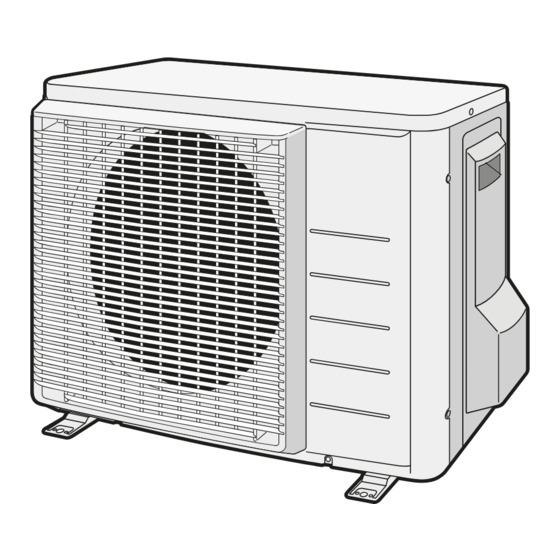
About the box 4 About the box 4.1 Overview: About the box This chapter describes what you have to do after the box with the outdoor unit is delivered on-site. Keep the following in mind: ▪ At delivery, the unit MUST be checked for damage. Any damage MUST be reported immediately to the claims agent of the carrier. -
Page 23: To Remove The Accessories From The Outdoor Unit
About the box 4.2.2 To remove the accessories from the outdoor unit 1 Lift the outdoor unit. CAUTION Only handle the outdoor unit as follows: 2 Remove the accessories at the bottom of the package. 1× 1× 1× 1× 1× General safety precautions Outdoor unit installation manual Fluorinated greenhouse gases label... -
Page 24: About The Unit
The refrigerant inside this unit is mildly flammable. INFORMATION For the operation limits see the latest technical data of the outdoor unit on the regional Daikin website (publicly accessible). 5.1 Overview: About the unit This chapter contains information about: ▪... -
Page 25: Unit Installation
Unit installation 6 Unit installation WARNING Installation shall be done by an installer, the choice of materials and installation shall comply with the applicable legislation. In Europe, EN378 is the applicable standard. In this chapter Preparing the installation site ..............................6.1.1 Installation site requirements of the outdoor unit .................... -
Page 26: Installation Site Requirements Of The Outdoor Unit
Unit installation WARNING The appliance shall be stored in a room without continuously operating ignition sources (example: open flames, an operating gas appliance or an operating electric heater). 6.1.1 Installation site requirements of the outdoor unit INFORMATION Also read the following requirements: ▪... - Page 27 Unit installation Baffle plate Prevailing wind direction Air outlet Do NOT install the unit in the following places: ▪ Sound sensitive areas (e.g. near a bedroom), so that the operation noise will cause no trouble. Note: If the sound is measured under actual installation conditions, the measured value might be higher than the sound pressure level mentioned in Sound spectrum in the data book due to environmental noise and sound reflections.
-
Page 28: Additional Installation Site Requirements Of The Outdoor Unit In Cold Climates
Unit installation ▪ Mind the service space requirements when installing the windbreaker. Sea wind Building Outdoor unit Windbreaker The outdoor unit is designed for outdoor installation only, and for ambient temperatures within the following ranges: Cooling mode Heating mode –10~46°C DB –25~24°C DB 6.1.2 Additional installation site requirements of the outdoor unit in cold climates Protect the outdoor unit against direct snowfall and take care that the outdoor unit... -
Page 29: Opening The Unit
Unit installation 6.2 Opening the unit 6.2.1 About opening the unit At certain times, you have to open the unit. Example: ▪ When connecting the refrigerant piping ▪ When connecting the electrical wiring ▪ When maintaining or servicing the unit DANGER: RISK OF ELECTROCUTION Do NOT leave the unit unattended when the service cover is removed. -
Page 30: Precautions When Mounting The Outdoor Unit
Unit installation 6.3.2 Precautions when mounting the outdoor unit INFORMATION Also read the precautions and requirements in the following chapters: ▪ "2 General safety precautions" [ 5] ▪ "6.1 Preparing the installation site" [ 25] 6.3.3 To provide the installation structure Check the strength and level of the installation ground so that the unit will not cause any operating vibration or noise. -
Page 31: To Install The Outdoor Unit
Unit installation 6.3.4 To install the outdoor unit 4× M8/M10 6.3.5 To provide drainage ▪ Make sure that condensation water can be evacuated properly. ▪ Install the unit on a base to make sure that there is proper drainage in order to avoid ice accumulation. - Page 32 Unit installation RXTM30+40N2V1B + RXTP25+35N2V1B9 + RXTP25+35N2V1B8 + Installer reference guide ARXTP25+35N2V1B + RXTA30N2V1B R32 split series 4P518023-7H – 2020.08...
-
Page 33: Piping Installation
Piping installation 7 Piping installation In this chapter Preparing refrigerant piping ..............................7.1.1 Refrigerant piping requirements ........................... 7.1.2 Refrigerant piping insulation..........................7.1.3 Refrigerant piping length and height difference ....................Connecting the refrigerant piping............................7.2.1 About connecting the refrigerant piping....................... 7.2.2 Precautions when connecting the refrigerant piping.................... -
Page 34: Refrigerant Piping Length And Height Difference
Piping installation Pipe outer diameter (Ø ) Insulation inner diameter Insulation thickness (t) (Ø 6.4 mm (1/4") 8~10 mm ≥10 mm 9.5 mm (3/8") 12~15 mm Ø Ø Ø Ø If the temperature is higher than 30°C and the humidity is higher than RH 80%, the thickness of the insulation materials should be at least 20 ... -
Page 35: Precautions When Connecting The Refrigerant Piping
Piping installation ▪ Keeping in mind the guidelines for: Pipe bending Flaring pipe ends Using the stop valves 7.2.2 Precautions when connecting the refrigerant piping INFORMATION Also read the precautions and requirements in the following chapters: ▪ "2 General safety precautions" [ 5] ▪... -
Page 36: Guidelines When Connecting The Refrigerant Piping
Piping installation Unit Installation period Protection method Outdoor unit >1 month Pinch the pipe <1 month Pinch or tape the pipe Indoor unit Regardless of the period INFORMATION Do NOT open the refrigerant stop valve before checking the refrigerant piping. When you need to charge additional refrigerant it is recommended to open the refrigerant stop valve after charging. -
Page 37: To Flare The Pipe End
Piping installation 7.2.5 To flare the pipe end CAUTION ▪ Incomplete flaring may cause refrigerant gas leakage. ▪ Do NOT re-use flares. Use new flares to prevent refrigerant gas leakage. ▪ Use flare nuts that are included with the unit. Using different flare nuts may cause refrigerant gas leakage. - Page 38 Piping installation Service port and service port cap Valve stem Field piping connection Stem cap ▪ Keep both stop valves open during operation. ▪ Do NOT apply excessive force to the valve stem. Doing so may break the valve body. ▪...
-
Page 39: To Connect The Refrigerant Piping To The Outdoor Unit
Piping installation ▪ After handling the stop valve, tighten the stem cap, and check for refrigerant leaks. Item Tightening torque (N∙m) Stem cap, liquid side 14.2~17.2 Stem cap, gas side 17.1~20.9 To handle the service cap ▪ ALWAYS use a charge hose equipped with a valve depressor pin, since the service port is a Schrader type valve. -
Page 40: Precautions When Checking The Refrigerant Piping
Piping installation Typical workflow Checking the refrigerant piping typically consists of the following stages: Checking for leaks in the refrigerant piping. Performing vacuum drying to remove all moisture, air or nitrogen from the refrigerant piping. If there is a possibility of moisture being present in the refrigerant piping (for example, water may have entered the piping), first carry out the vacuum drying procedure below until all moisture has been removed. -
Page 41: To Perform Vacuum Drying
Piping installation 7.3.4 To perform vacuum drying DANGER: RISK OF EXPLOSION Do NOT start the unit if it is vacuumed. Connect the vacuum pump and manifold as follows: Low pressure gauge Gauge manifold High pressure gauge Low-pressure valve (Lo) High-pressure valve (Hi) Charging hoses Vacuum pump Valve caps... - Page 42 Piping installation INFORMATION After opening the stop valve, it is possible that the pressure in the refrigerant piping does NOT increase. This might be caused by e.g. the closed state of the expansion valve in the outdoor unit circuit, but does NOT present any problem for correct operation of the unit.
-
Page 43: Charging Refrigerant
Charging refrigerant 8 Charging refrigerant In this chapter About charging refrigerant..............................About the refrigerant ................................Precautions when charging refrigerant ..........................To determine the additional refrigerant amount ........................To determine the complete recharge amount ........................To charge additional refrigerant ............................To fix the fluorinated greenhouse gases label ........................8.1 About charging refrigerant The outdoor unit is factory charged with refrigerant, but in some cases the following might be necessary:... -
Page 44: About The Refrigerant
Charging refrigerant Typical workflow – Completely recharging refrigerant typically consists of the following stages: 1 Determining how much refrigerant to charge. 2 Charging refrigerant. 3 Filling in the fluorinated greenhouse gases label, and fixing it to the inside of the outdoor unit. 8.2 About the refrigerant This product contains fluorinated greenhouse gases. -
Page 45: Precautions When Charging Refrigerant
Charging refrigerant 8.3 Precautions when charging refrigerant INFORMATION Also read the precautions and requirements in the following chapters: ▪ "2 General safety precautions" [ 5] ▪ "7.1 Preparing refrigerant piping" [ 33] 8.4 To determine the additional refrigerant amount If the total liquid piping Then…... -
Page 46: To Fix The Fluorinated Greenhouse Gases Label
Charging refrigerant If pump down is needed in case of dismantling or relocating the system, see "16.2 To pump down" [ 62] for more details. 8.7 To fix the fluorinated greenhouse gases label 1 Fill in the label as follows: Contains fluorinated greenhouse gases RXXX GWP: XXX GWP ×... -
Page 47: Electrical Installation
Electrical installation 9 Electrical installation In this chapter About connecting the electrical wiring ..........................9.1.1 Precautions when connecting the electrical wiring ....................9.1.2 Guidelines when connecting the electrical wiring ....................9.1.3 Specifications of standard wiring components ..................... To connect the electrical wiring to the outdoor unit ......................9.1 About connecting the electrical wiring Before connecting the electrical wiring Make sure:... - Page 48 Electrical installation WARNING ▪ If the power supply has a missing or wrong N-phase, equipment might break down. ▪ Establish proper earthing. Do NOT earth the unit to a utility pipe, surge absorber, or telephone earth. Incomplete earthing may cause electrical shock. ▪...
-
Page 49: Guidelines When Connecting The Electrical Wiring
Electrical installation c g e d f Multimeter (DC voltage range) S80 – reversing solenoid valve lead wire S70 – fan motor lead wire S90 – thermistor lead wire S20 – electronic expansion valve lead wire S40 – thermal overload relay lead wire DB1 - diode bridge 9.1.2 Guidelines when connecting the electrical wiring Keep the following in mind:... -
Page 50: Specifications Of Standard Wiring Components
Electrical installation Tightening torques Item Tightening torque (N•m) M4 (X1M) 1.5~1.6 M4 (earth) 1.4~1.5 ▪ The earth wire between the wire retainer and the terminal must be longer than the other wires. 9.1.3 Specifications of standard wiring components Component Power supply cable Voltage 220~240 V Phase... - Page 51 Electrical installation 50 Hz 220-240 V Interconnection cable Power supply cable Circuit breaker Residual current device Power supply Earth 3× 5 Tighten the terminal screws securely. We recommend using a Phillips screwdriver. RXTM30+40N2V1B + RXTP25+35N2V1B9 + RXTP25+35N2V1B8 + Installer reference guide ARXTP25+35N2V1B + RXTA30N2V1B R32 split series 4P518023-7H –...
-
Page 52: Finishing The Outdoor Unit Installation
Finishing the outdoor unit installation 10 Finishing the outdoor unit installation 10.1 To finish the outdoor unit installation DANGER: RISK OF ELECTROCUTION ▪ Make sure that the system is earthed properly. ▪ Turn off the power supply before servicing. ▪ Install the service cover before turning on the power supply. -
Page 53: Configuration
Configuration 11 Configuration 11.1 Facility setting Use this function for cooling at low outdoor temperature. This function is designed for facilities such as equipment of computer rooms. NEVER use in a residence or office where people occupy the space. 11.1.1 To set the facility mode When cutting jumper J6 on the PCB, the operation range will expand to –15°C. -
Page 54: Commissioning
Commissioning 12 Commissioning In this chapter 12.1 Overview: Commissioning ..............................12.2 Precautions when commissioning............................12.3 Checklist before commissioning............................. 12.4 Checklist during commissioning ............................. 12.5 To perform a test run ................................12.6 Starting up the outdoor unit ..............................12.1 Overview: Commissioning This chapter describes what you have to do and know to commission the system after it is installed. -
Page 55: Checklist During Commissioning
Commissioning The indoor unit is properly mounted. The outdoor unit is properly mounted. The system is properly earthed and the earth terminals are tightened. The power supply voltage matches the voltage on the identification label of the unit. There are NO loose connections or damaged electrical components in the switch box. There are NO damaged components or squeezed pipes on the inside of the indoor and outdoor units. -
Page 56: Starting Up The Outdoor Unit
Commissioning INFORMATION ▪ Even if the unit is turned OFF, it consumes electricity. ▪ When the power turns back on after a power break, the previously selected mode will be resumed. 12.6 Starting up the outdoor unit See the indoor unit installation manual for configuration and commissioning of the system. -
Page 57: Hand-Over To The User
Hand-over to the user 13 Hand-over to the user Once the test run is finished and the unit operates properly, please make sure the following is clear for the user: ▪ Make sure that the user has the printed documentation and ask him/her to keep it for future reference. -
Page 58: Maintenance And Service
Maintenance and service 14 Maintenance and service NOTICE Maintenance MUST be done by an authorized installer or service agent. We recommend performing maintenance at least once a year. However, applicable legislation might require shorter maintenance intervals. NOTICE Applicable legislation on fluorinated greenhouse gases requires that the refrigerant charge of the unit is indicated both in weight and CO equivalent. -
Page 59: About The Compressor
Maintenance and service ▪ Heat exchanger The heat exchanger of the outdoor unit can get blocked up due to dust, dirt, leaves, etc. It is recommended to clean the heat exchanger yearly. A blocked heat exchanger can lead to too low pressure or too high pressure leading to worse performance. -
Page 60: Troubleshooting
Troubleshooting 15 Troubleshooting 15.1 Overview: Troubleshooting This chapter describes what you have to do in case of problems. It contains information about solving problems based on symptoms. Before troubleshooting Carry out a thorough visual inspection of the unit and look for obvious defects such as loose connections or defective wiring. -
Page 61: Symptom: The Unit Is Not Heating Or Cooling As Expected
Troubleshooting 15.3.2 Symptom: The unit is NOT heating or cooling as expected Possible causes Corrective action Wrong connection of the electrical Connect the electrical wires correctly. wires Gas leakage Check for gas leakage. 15.3.3 Symptom: Water leakage Possible causes Corrective action Incomplete thermal insulation (gas and Make sure the thermal insulation of the liquid piping, indoor portions of the... -
Page 62: Disposal
Disposal 16 Disposal NOTICE Do NOT try to dismantle the system yourself: dismantling of the system, treatment of the refrigerant, oil and other parts MUST comply with applicable legislation. Units MUST be treated at a specialised treatment facility for reuse, recycling and recovery. 16.1 Overview: Disposal Typical workflow Disposing of the system typically consists of the following stages:... -
Page 63: To Start And Stop Forced Cooling
Disposal Gas stop valve Closing direction Hexagonal wrench Valve cap Liquid stop valve 16.3 To start and stop forced cooling There are 2 methods to perform forced cooling. ▪ Method 1. Using the indoor unit ON/OFF switch (if present on the indoor unit). ▪... -
Page 64: Technical Data
Technical data 17 Technical data ▪ A subset of the latest technical data is available on the regional Daikin website (publicly accessible). ▪ The full set of latest technical data is available on the Daikin Business Portal (authentication required). 17.1 Wiring diagram 17.1.1 Unified wiring diagram legend... - Page 65 Technical data Symbol Meaning AC*, CN*, E*, HA*, HE*, HL*, HN*, HR*, Connection, connector MR*_A, MR*_B, S*, U, V, W, X*A, K*R_*, NE D*, V*D Diode Diode bridge DIP switch Heater FU*, F*U, (for characteristics, refer to Fuse PCB inside your unit) Connector (frame ground) Harness H*P, LED*, V*L...
- Page 66 Technical data Symbol Meaning Thermo switch Residual current device Resistor Thermistor Receiver Limit switch Float switch S*NG Refrigerant leak detector S*NPH Pressure sensor (high) S*NPL Pressure sensor (low) S*PH, HPS* Pressure switch (high) S*PL Pressure switch (low) Thermostat S*RH Humidity sensor S*W, SW* Operation switch SA*, F1S...
-
Page 67: Piping Diagram
Technical data 17.2 Piping diagram 17.2.1 Piping diagram: Outdoor unit PED categories of equipment – High pressure switch: category IV; Compressor: category II; Other equipment: art. 4§3. ·6x7.0· CuT ·6x7.0· CuT ·12.7· CuT ·7.9· CuT ·6.4· CuT ·9.5· CuT ·6x3.2· CuT ·9.5·... -
Page 68: Glossary
Optional equipment Equipment made or approved by Daikin that can be combined with the product according to the instructions in the accompanying documentation. Field supply Equipment NOT made by Daikin that can be combined with the product according to the instructions in the accompanying documentation. - Page 72 4P518023-7H 2020.08 Verantwortung für Energie und Umwelt...