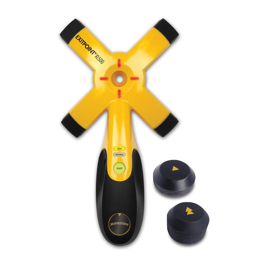
DEVICE OVERVIEW

MAGNETS
*  and
and  = South Pole
*Yellow side = North Pole

NOT SHOWN:
- 9V battery
- Reusable adhesive disks (9)
- Protective case for storage and carrying
The Zircon® ExitPoint® XL500 is designed to detect exit points through walls before drilling and coring. It operates in one of two modes:
- Normal Scan is optimized for interior walls with 1⁄2" (1.3 cm) drywall on both sides, up to 41⁄2" (11.4 cm) thick
- DeepScan® is for use with thicker walls, up to 9" (22.9 cm)
NOTE: Accuracy will be impacted unless instructions are carefully followed.
Detection depth can vary due to wall material and construction.
INSTALL 9-VOLT BATTERY
Install 9V battery, as shown.
Always use a new 9V alkaline battery with an extended expiration date at least 3 years beyond the current date.
Be sure not to pull on wires when disconnecting an old battery.

POWER UP
To activate Receiver, press the Power / Mode Button.
Lights will flash as tool automatically calibrates, then a beep will sound, and the Ready Indicator LED will light green to indicate the device is ready for use.
A calibration error is indicated by top and bottom Directional Indicator LEDs flashing alternately with left and right LEDs. Move the Receiver away from the suspected location of the Target Magnet and recalibrate.
POWER DOWN
To power down, press and hold Power / Mode Button for 2 seconds. Lights will turn off.
Tool will also automatically power down 3 minutes after last calibration.
USE NORMAL SCAN MODE
The Receiver powers up in Normal Scan Mode, as indicated by the Normal Scan Mode Indicator light. Always use the Small Target Magnet when scanning in this mode. (Figure A)

- Determine where the drill exit hole should be. Clean the surface of any dust or oils, and make sure the surface is dry.
Remove the protective plastic from both sides of an adhesive disk, then use the disk to affix the Small Target Magnet to the spot, with the yellow side facing away from wall. (Figure B)
![]()

NOTE: Do not discard the protective plastic covers for a disk. The disk can be reused if covered again and stored after use.
- Move the Receiver horizontally or vertically. The amber Directional Indicator LEDs will point toward the target. When the Receiver is near the Target Magnet, all of the Directional Indicator LEDs will light red. Mark the spot with a pencil through the Circular Cutout. (Figure C)
![]()

NOTE: If the unit indicates a large target area, refine the scan to more accurately find the target location.
REFINE NORMAL SCAN MODE
- Move the Receiver horizontally. The amber Directional Indicator LEDs will point toward the target. When the Receiver is near the Target Magnet, all of the Directional Indicator LEDs will light red. Mark the spot with a pencil through the Circular Cutout. (Figure C)
- Continue scanning in the same direction until the Directional Indicator LEDs until the Directional Indicator LEDs revert to amber, then reverse direction. Mark the location where all of the Directional Indicator LEDs light red.
The approximate midpoint of the target is between the two marks. (Figure D)
![]()
- Without recalibrating, move the Receiver to the midpoint, then scan vertically until the top and bottom limits are marked. The center of the Target Magnet should be the midpoint between the top and bottom marks. (Figure E)
![]()


USE DEEPSCAN® MODE
DeepScan® Mode scans up to 9" (22.9 cm) thick.
For DeepScan®, always use the Large Target Magnet. (Figure F)

- Power up Receiver, then double press Power / Mode Button to switch to DeepScan® Mode. The DeepScan® Mode Indicator light will illuminate.
- Move the Receiver horizontally or vertically. The amber Directional Indicator LEDs will point toward the target. When the Receiver is near the Target Magnet, all of the Directional Indicator LEDs will light red. Mark the spot with a pencil through the Circular Cutout. (Figure C)
NOTE: If the unit indicates a large target area, refine the scan to more accurately find the target location.
REFINE DEEPSCAN® MODE
While in DeepScan® mode, refer to REFINE NORMAL SCAN MODE steps 2 – 4.
STORING REUSABLE ADHESIVE DISKS
This tool comes with 9 double-sided, reusable adhesive disks. With repetitive use or exposure to dust particles, disks may lose stickiness. Gently wash with soapy water, rinse, air dry, and reuse.
The disks can be stored in the case.
To order more reusable adhesive disks, email [email protected].
MAGNET SAFETY WARNINGS

The ExitPoint® XL500 magnets are very strong and are more powerful than other kinds of magnets. HANDLE WITH CARE TO AVOID PERSONAL INJURY OR DAMAGE TO THE MAGNETS. Fingers and other body parts can be pinched between two magnets.
- KEEP MAGNETS AWAY FROM CHILDREN. The ExitPoint® XL500 magnets are not toys. Children should not be allowed to handle these magnets.
- EXITPOINT® XL500 MAGNETS CAN AFFECT PACEMAKERS. The strong magnetic fields near these magnets may affect pacemakers, implanted cardioverter defibrillators, and other medical devices. Many of these devices employ a feature that deactivates them with a magnetic field. Therefore, EXTREME care must be taken to avoid inadvertently deactivating such devices.
- EXITPOINT® XL500 MAGNETS ARE BRITTLE. Despite being made of metal and covered in rubber and plastic, these magnets are not as durable as steel and should be handled with care.
DO NOT REMOVE COVERING. These magnets can peel, chip, crack, or shatter if allowed to slam together. Eye protection should be worn since shattering magnets can launch small pieces at great speeds. - MAGNETS CAN AFFECT MAGNETIC MEDIA. The strong magnetic fields near these magnets can damage magnetic media such as floppy disks, credit cards, magnetic I.D. cards, cassette tapes, video tapes, or other such devices. They can also damage wireless phones, televisions, VCRs, computer monitors, and CRT displays. DO NOT PLACE magnets near electronic appliances.
- MAGNETS MAY BECOME DEMAGNETIZED AT HIGH TEMPERATURES. DO NOT EXCEED 175°F (80°C).
- MAGNET POWDER OR DUST IS FLAMMABLE. Avoid drilling or machining these magnets. When ground into a dust or powder, this material is highly flammable.
DO NOT DRILL OR MACHINE. - THOSE WITH NICKEL ALLERGIES SHOULD AVOID PROLONGED CONTACT WITH UNCOVERED MAGNETS. If you have a nickel allergy, avoid directly handling these uncovered magnets.
- STRONG MAGNETIC FIELDS CAN INTERFERE WITH COMPASSES AND NAVIGATION. IATA (International Air Transport Association) and US Federal rules and regulations cover shipping magnets by air and ground delivery. Magnetic fields can influence compasses, magnetometers used in air transport, and internal compasses of smartphone and GPS devices.
- THESE MAGNETS CAN CORRODE. These magnets are not waterproof. If used underwater, outdoors, or in a moist environment, they can rust, corrode, and lose magnetic strength.
TROUBLESHOOTING & CONSTRUCTION TIPS
| SITUATION | LIKELY CAUSE | SOLUTION |
| Battery level too low for proper operation. | Replace with brand new 9V alkaline battery. |
| Solid red Directional Indicator LEDs flicker when Receiver is believed to be over Target Magnet. | Receiver needs to be recalibrated. | Move receiver away from suspected target location, recalibrate, then restart search for Target Magnet. |
| Target Magnet is oriented with yellow side towards wall or target is too far away. | Orient Target Magnet with yellow side away from wall. | |
| Directional Indicator LEDs continue to flicker after several recalibration attempts. | Receiver is unable to locate Target Magnet in this particular location. | Change to DeepScan ® Mode (Large Target Magnet) and rescan for Target Magnet. |
| Unable to locate Target Magnet. | Target magnet is oriented with yellow side facing wall. | Orient Target Magnet away from wall with yellow side facing out. |
| Receiver is within approximately 1" (25 mm) of Target Magnet. | If Receiver is too close to Target Magnet, magnetic lines wrap around magnet. Move Receiver further away from Target Magnet and rescan. | |
| Target Magnet distance exceeds scan mode specifications. | Check scan depth, Target Magnet size, and scan mode. |
| DISPLAY | INDICATES |
| Normal Scan Mode Indicator LED is illuminated. | Tool is in Normal Scan Mode. Use Small Target Magnet marked . |
| DeepScan ® Mode Indicator LED is illuminated. | Tool is in DeepScan ® Mode. Use Large Target Magnet marked . |
| Amber Directional Indicator LEDs flash in clockwise circular motion. | Tool is calibrating. Wait for it to finish before scanning. |
| All LEDs on for approximately 1 second. A short beep sounds. | Calibration is complete. Receiver is ready to scan. |
| Red LEDs flash. |
|
| Red LEDs on. | Target is located. |
| Amber top and bottom LEDs flash alternately with left and right LEDs. | Calibration error. Recalibrate again. |
Visit www.zircon.com for the most current instructions.


Documents / Resources
References
Download manual
Here you can download full pdf version of manual, it may contain additional safety instructions, warranty information, FCC rules, etc.
Thank you! Your question has been received!
Need Assistance?
Do you have a question about the ExitPoint XL500 that isn't answered in the manual? Leave your question here.