Table of Contents
Quick Links
www.ti.com
User's Guide
Light Sensor Evaluation Modules
This user's guide describes the characteristics, operation, and use of the OPT light sensor evaluation modules
(OPTEVM). The user's guide details how to set up and configure the software and hardware, and reviews
various aspects of the program operation. Throughout this document, the terms evaluation board, evaluation
module, and EVM are synonymous with the OPT light sensor EVM (OPTEVM). This document also includes an
electrical schematic, printed circuit board (PCB) layout drawings, and a parts list for the EVM.
This user's guide is applicable for the following devices:
Device
OPT3005DTSEVM
OPT4001DTSEVM
OPT4048DTSEVM
OPT4001DNPQ1EVM
1
Overview..................................................................................................................................................................................3
1.1 OPTEVM Kit Contents.......................................................................................................................................................
1.2 Related Documentation from Texas Instruments...............................................................................................................
2 OPTEVM Hardware Overview................................................................................................................................................
Software...................................................................................................................................................................6
3.1 Hardware Requirements....................................................................................................................................................
Installation...........................................................................................................................................................6
3.4 Launching the OPT300x/4xxxEVM Software...................................................................................................................
3.5 OPTEVM Software Operation..........................................................................................................................................
3.6
Controls............................................................................................................................................................................14
Variants................................................................................................................................................15
3.8 Scripts Window................................................................................................................................................................
4 Schematic, PCB Layout, and Bill of Materials...................................................................................................................
4.1 Coupon Board..................................................................................................................................................................
4.2
Motherboard.....................................................................................................................................................................23
5
Troubleshooting....................................................................................................................................................................27
5.1 Microsoft Windows 7 Manual Driver Installation..............................................................................................................
6 Revision History...................................................................................................................................................................
SBOU293B - NOVEMBER 2022 - REVISED JULY 2023
Submit Document Feedback
ABSTRACT
Table 1-1. Devices Supported
Description
Ambient Light Sensor (ALS) for Video Surveillance Cameras
High-Speed, High-Resolution, Digital Ambient Light Sensor (ALS)
High-Speed, High-Precision Tristimulus XYZ Color Sensor
Automotive High-Speed, High-Resolution, Digital Ambient Light Sensor (ALS)
Table of Contents
Setup...................................................................................................................................10
Copyright © 2023 Texas Instruments Incorporated
Table of Contents
Light Sensor Evaluation Modules
3
4
5
6
11
13
17
20
20
27
33
1
Table of Contents

Related Manuals for Texas Instruments OPT3005DTSEVM


Summary of Contents for Texas Instruments OPT3005DTSEVM
-
Page 1: Table Of Contents
High-Speed, High-Precision Tristimulus XYZ Color Sensor OPT4001DNPQ1EVM Automotive High-Speed, High-Resolution, Digital Ambient Light Sensor (ALS) Table of Contents Overview....................................3 1.1 OPTEVM Kit Contents............................... 1.2 Related Documentation from Texas Instruments....................... 2 OPTEVM Hardware Overview..............................3 OPTEVM Software...................................6 3.1 Hardware Requirements..............................3.2 Software Installation................................6... - Page 2 , and Windows ® are registered trademarks of Microsoft Corporation. All trademarks are the property of their respective owners. Light Sensor Evaluation Modules SBOU293B – NOVEMBER 2022 – REVISED JULY 2023 Submit Document Feedback Copyright © 2023 Texas Instruments Incorporated...
-
Page 3: Overview
Overview 1 Overview Texas Instruments has multiple families of light sensor parts. This EVM user's guide supports all the devices listed above. Each of these parts is a light sensor integrated circuit (IC) with a digital output and works with the I C protocol;... -
Page 4: Related Documentation From Texas Instruments
The latest revision can be found by clicking the link and is also available from the TI web site, the Texas Instruments' Literature Response Center at (800) 477-8924, and the Product Information Center at (972) 644-5580. When ordering, identify the document by both title and literature number. -
Page 5: Optevm Hardware Overview
OPTEVM, including the use of a grounded wrist strap at an approved ESD workstation. Figure 2-1. OPTEVM Hardware Setup SBOU293B – NOVEMBER 2022 – REVISED JULY 2023 Light Sensor Evaluation Modules Submit Document Feedback Copyright © 2023 Texas Instruments Incorporated... -
Page 6: Optevm Software
Figure 3-2. OPTEVM Software-Installation Launch Follow the prompts as shown in Figure 3-3 Figure 3-8 to install the OPTEVM software. Light Sensor Evaluation Modules SBOU293B – NOVEMBER 2022 – REVISED JULY 2023 Submit Document Feedback Copyright © 2023 Texas Instruments Incorporated... -
Page 7: Figure 3-3. Optevm Software-Installation Prompts
OPTEVM Software Figure 3-3. OPTEVM Software-Installation Prompts Figure 3-4. OPTEVM Software-Installation Prompts SBOU293B – NOVEMBER 2022 – REVISED JULY 2023 Light Sensor Evaluation Modules Submit Document Feedback Copyright © 2023 Texas Instruments Incorporated... -
Page 8: Figure 3-5. Optevm Software-Installation Prompts
OPTEVM Software www.ti.com Figure 3-5. OPTEVM Software-Installation Prompts Figure 3-6. OPTEVM Software-Installation Prompts Light Sensor Evaluation Modules SBOU293B – NOVEMBER 2022 – REVISED JULY 2023 Submit Document Feedback Copyright © 2023 Texas Instruments Incorporated... -
Page 9: Figure 3-7. Optevm Software-Installation Prompts
OPTEVM Software Figure 3-7. OPTEVM Software-Installation Prompts Figure 3-8. OPTEVM Software-Installation Prompts The OPTEVM GUI software is now installed. SBOU293B – NOVEMBER 2022 – REVISED JULY 2023 Light Sensor Evaluation Modules Submit Document Feedback Copyright © 2023 Texas Instruments Incorporated... -
Page 10: Typical Optevm Hardware Setup
Connect the EVM via USB to the PC. If Windows shows a notification that a driver is not found for the device connected, then see the instructions to manually install drivers in Section 5.1 before proceeding. Light Sensor Evaluation Modules SBOU293B – NOVEMBER 2022 – REVISED JULY 2023 Submit Document Feedback Copyright © 2023 Texas Instruments Incorporated... -
Page 11: Launching The Opt300X/4Xxxevm Software
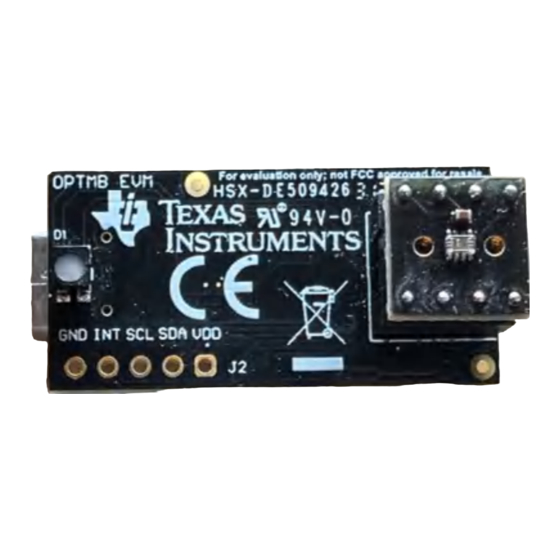
Check the USB connection and that the OPTMB EVM board appears in the device manager as shown. A green SBOU293B – NOVEMBER 2022 – REVISED JULY 2023 Light Sensor Evaluation Modules Submit Document Feedback Copyright © 2023 Texas Instruments Incorporated... -
Page 12: Figure 3-12. Hardware Error Message
PC and the GUI Start Capture button has not been clicked. Figure 3-12. Hardware Error Message Light Sensor Evaluation Modules SBOU293B – NOVEMBER 2022 – REVISED JULY 2023 Submit Document Feedback Copyright © 2023 Texas Instruments Incorporated... -
Page 13: Optevm Software Operation
There is also an auto option that dynamically changes the range to match the data. Scrolling zooms in to or zooms out from the plot. Left-clicking and dragging displays a yellow rectangle that, upon releasing SBOU293B – NOVEMBER 2022 – REVISED JULY 2023 Light Sensor Evaluation Modules Submit Document Feedback Copyright © 2023 Texas Instruments Incorporated... -
Page 14: Controls
Oneshot (AGC) keeps the device is standby mode and a conversion is triggered by an interrupt (INT Pin) or a Light Sensor Evaluation Modules SBOU293B – NOVEMBER 2022 – REVISED JULY 2023 Submit Document Feedback Copyright © 2023 Texas Instruments Incorporated... -
Page 15: Optxxxdtsevm Variants
The Lux Live window, shown in Figure 3-15, shows the live lux value sensed by the OPT4048 across the sample count. SBOU293B – NOVEMBER 2022 – REVISED JULY 2023 Light Sensor Evaluation Modules Submit Document Feedback Copyright © 2023 Texas Instruments Incorporated... -
Page 16: Figure 3-15. Opt4048Dtsevm Lux Live Window
3-16, shows the live register codes of each channel around the sample count. Figure 3-16. OPT4048DTSEVM Channel Live Window Light Sensor Evaluation Modules SBOU293B – NOVEMBER 2022 – REVISED JULY 2023 Submit Document Feedback Copyright © 2023 Texas Instruments Incorporated... -
Page 17: Scripts Window
Launch the registers view by double-clicking on the Registers View button under the Device List box on the right side of the screen. SBOU293B – NOVEMBER 2022 – REVISED JULY 2023 Light Sensor Evaluation Modules Submit Document Feedback Copyright © 2023 Texas Instruments Incorporated... - Page 18 To do this, select the launchGUI.py script and click Run>Buffer or press F5. Light Sensor Evaluation Modules SBOU293B – NOVEMBER 2022 – REVISED JULY 2023 Submit Document Feedback Copyright © 2023 Texas Instruments Incorporated...
-
Page 19: Figure 3-18. Registers View Example For Opt4Xxx
Registers x08 and x09 allow low and high limits, respectively, to be set. These registers are used in certain interrupt reporting modes. The Design_ID is contained in register 0x11. SBOU293B – NOVEMBER 2022 – REVISED JULY 2023 Light Sensor Evaluation Modules Submit Document Feedback Copyright © 2023 Texas Instruments Incorporated... -
Page 20: Schematic, Pcb Layout, And Bill Of Materials
For other OPT300x/4xxx device variants, the pinout and schematic are the same except for the change to the IC in the BOM. Figure 4-1. OPT3004 Coupon Board Schematic Light Sensor Evaluation Modules SBOU293B – NOVEMBER 2022 – REVISED JULY 2023 Submit Document Feedback Copyright © 2023 Texas Instruments Incorporated... -
Page 21: Figure 4-2. Pcb Top Layer
PCB layers, respectively. Figure 4-2. PCB Top Layer Figure 4-3. PCB Bottom Layer SBOU293B – NOVEMBER 2022 – REVISED JULY 2023 Light Sensor Evaluation Modules Submit Document Feedback Copyright © 2023 Texas Instruments Incorporated... -
Page 22: Figure 4-4. Pcb Top-Layer Assembly Drawing
Schematic, PCB Layout, and Bill of Materials www.ti.com Figure 4-4. PCB Top-Layer Assembly Drawing Figure 4-5. PCB Bottom-Layer Assembly Drawing Light Sensor Evaluation Modules SBOU293B – NOVEMBER 2022 – REVISED JULY 2023 Submit Document Feedback Copyright © 2023 Texas Instruments Incorporated... -
Page 23: Motherboard
Alternatively, a header can be populated at J2 for easier access. Figure 4-6. OPTMB EVM Board Schematic SBOU293B – NOVEMBER 2022 – REVISED JULY 2023 Light Sensor Evaluation Modules Submit Document Feedback Copyright © 2023 Texas Instruments Incorporated... -
Page 24: Figure 4-7. Pcb Top Layer
PCB layers, respectively. Figure 4-7. PCB Top Layer Figure 4-8. PCB Bottom Layer Light Sensor Evaluation Modules SBOU293B – NOVEMBER 2022 – REVISED JULY 2023 Submit Document Feedback Copyright © 2023 Texas Instruments Incorporated... -
Page 25: Figure 4-9. Pcb Top-Layer Assembly Drawing
Schematic, PCB Layout, and Bill of Materials Figure 4-9. PCB Top-Layer Assembly Drawing Figure 4-10. PCB Bottom-Layer Assembly Drawing SBOU293B – NOVEMBER 2022 – REVISED JULY 2023 Light Sensor Evaluation Modules Submit Document Feedback Copyright © 2023 Texas Instruments Incorporated... - Page 26 Header, 2.54mm, 5x1, Gold, TH 61300511121 Wurth Elektronik RES, 0, 5%, .05 W, AEC-Q200 ERJ-1GN0R00C Panasonic Grade 0, 0201 Light Sensor Evaluation Modules SBOU293B – NOVEMBER 2022 – REVISED JULY 2023 Submit Document Feedback Copyright © 2023 Texas Instruments Incorporated...
-
Page 27: Troubleshooting
7 With Drivers not Installed 1. Open the device manager. 2. Right click on USB Serial Device and select Properties. SBOU293B – NOVEMBER 2022 – REVISED JULY 2023 Light Sensor Evaluation Modules Submit Document Feedback Copyright © 2023 Texas Instruments Incorporated... - Page 28 Troubleshooting www.ti.com 3. Click the Update Driver button. 4. Click Browse my computer for driver software Light Sensor Evaluation Modules SBOU293B – NOVEMBER 2022 – REVISED JULY 2023 Submit Document Feedback Copyright © 2023 Texas Instruments Incorporated...
- Page 29 5. Click Let me pick from a list of device drivers on my computer. 6. Select Show All Devices and click the Next button. SBOU293B – NOVEMBER 2022 – REVISED JULY 2023 Light Sensor Evaluation Modules Submit Document Feedback Copyright © 2023 Texas Instruments Incorporated...
-
Page 30
Troubleshooting www.ti.com 7. Click the Have Disk button. 8. Click the Browse button. 9. Navigate to “C:\Users\
\Documents\Texas Instruments\Latte\projects\OPT3004\drivers” and choose MSP430_CDC. Click the Open button. Light Sensor Evaluation Modules SBOU293B – NOVEMBER 2022 – REVISED JULY 2023 Submit Document Feedback... - Page 31 10. Click the OK button 11. Select the first USB serial device and click the Next button. 12. Click the Yes button. SBOU293B – NOVEMBER 2022 – REVISED JULY 2023 Light Sensor Evaluation Modules Submit Document Feedback Copyright © 2023 Texas Instruments Incorporated...
- Page 32 2 and step 11. In step 2, make sure to right-click the second USB Serial Device. Likewise, on step 11 make sure to select the second USB Serial Device when installing the driver as the following figure shows. Light Sensor Evaluation Modules SBOU293B – NOVEMBER 2022 – REVISED JULY 2023 Submit Document Feedback Copyright © 2023 Texas Instruments Incorporated...
-
Page 33: Revision History
16. The two USB Serial Device devices appear in the device manager under Ports (COM & LPT) as the following image shows. SBOU293B – NOVEMBER 2022 – REVISED JULY 2023 Light Sensor Evaluation Modules Submit Document Feedback Copyright © 2023 Texas Instruments Incorporated... - Page 34 Launching the OPT300x/4xxxEVM Software section • Added Table 3-2 to describe the supported devices for OPTxxxDTSEVM Variants section......• Added new variant............................15 Light Sensor Evaluation Modules SBOU293B – NOVEMBER 2022 – REVISED JULY 2023 Submit Document Feedback Copyright © 2023 Texas Instruments Incorporated...
- Page 35 STANDARD TERMS FOR EVALUATION MODULES Delivery: TI delivers TI evaluation boards, kits, or modules, including any accompanying demonstration software, components, and/or documentation which may be provided together or separately (collectively, an “EVM” or “EVMs”) to the User (“User”) in accordance with the terms set forth herein.
- Page 36 www.ti.com Regulatory Notices: 3.1 United States 3.1.1 Notice applicable to EVMs not FCC-Approved: FCC NOTICE: This kit is designed to allow product developers to evaluate electronic components, circuitry, or software associated with the kit to determine whether to incorporate such items in a finished product and software developers to write software applications for use with the end product.
- Page 37 www.ti.com Concernant les EVMs avec antennes détachables Conformément à la réglementation d'Industrie Canada, le présent émetteur radio peut fonctionner avec une antenne d'un type et d'un gain maximal (ou inférieur) approuvé pour l'émetteur par Industrie Canada. Dans le but de réduire les risques de brouillage radioélectrique à...
- Page 38 www.ti.com EVM Use Restrictions and Warnings: 4.1 EVMS ARE NOT FOR USE IN FUNCTIONAL SAFETY AND/OR SAFETY CRITICAL EVALUATIONS, INCLUDING BUT NOT LIMITED TO EVALUATIONS OF LIFE SUPPORT APPLICATIONS. 4.2 User must read and apply the user guide and other available documentation provided by TI regarding the EVM prior to handling or using the EVM, including without limitation any warning or restriction notices.
- Page 39 Notwithstanding the foregoing, any judgment may be enforced in any United States or foreign court, and TI may seek injunctive relief in any United States or foreign court. Mailing Address: Texas Instruments, Post Office Box 655303, Dallas, Texas 75265 Copyright © 2023, Texas Instruments Incorporated...
- Page 40 TI products. TI’s provision of these resources does not expand or otherwise alter TI’s applicable warranties or warranty disclaimers for TI products. TI objects to and rejects any additional or different terms you may have proposed. IMPORTANT NOTICE Mailing Address: Texas Instruments, Post Office Box 655303, Dallas, Texas 75265 Copyright © 2023, Texas Instruments Incorporated...