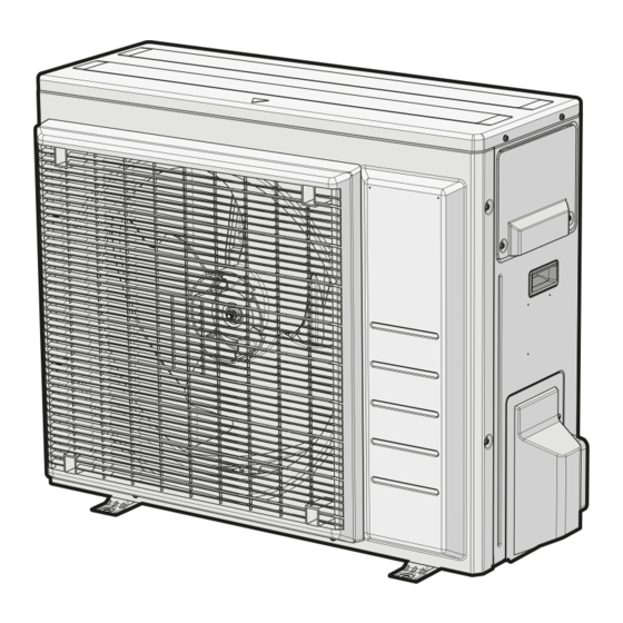
Daikin RXF71A2V1B Installation Manual
Hide thumbs
Also See for RXF71A2V1B:
- Installer's reference manual (76 pages) ,
- Installation manual (24 pages) ,
- Installer's reference manual (68 pages)
Table of Contents
Quick Links
Table of Contents

Summary of Contents for Daikin RXF71A2V1B
- Page 1 Installation manual R32 split series RXF50B2V1B RXF60B2V1B RXF71A2V1B ARXF50A2V1B ARXF60A2V1B ARXF71A2V1B RXP50M2V1B RXP60M2V1B RXP71M2V1B ARXM50R2V1B ARXM60R2V1B ARXM71R2V1B RXM42R2V1B RXM50R2V1B RXM60R2V1B RXM71R2V1B RXJ50N2V1B Installation manual RXA42B2V1B English R32 split series RXA50B2V1B...
- Page 2 2P518197-1D...
- Page 3 2P518197-1D...
- Page 4 2P518197-2D...
- Page 5 2P518197-2D...
- Page 6 2P518197-4D...
- Page 7 2P518197-4D...
- Page 8 2P518197-6E...
- Page 9 2P518197-6E...
- Page 10 2P518197-7G...
- Page 11 2P518197-7G...
-
Page 12: Table Of Contents
10.1 Fault diagnosis using LED on outdoor unit PCB ....... 20 Daikin website (publicly accessible). 11 Disposal ▪ The full set of latest technical data is available on the Daikin Business Portal (authentication required). 12 Technical data 12.1 Wiring diagram ................21 12.1.1... - Page 13 DANGER: RISK OF EXPLOSION cause accidents. Do NOT start the unit if it is vacuumed. ARXM50-71+RXM42~71R2V1B + RXP50~71M2V1B + Installation manual RXA42+50B2V1B + RXF50+60B2V1B + RXF71A2V1B + RXJ50N2V1B + ARXF50~71A2V1B R32 split series 3P512025-9S – 2020.05...
-
Page 14: About The Box
Do NOT remove the fan guard. When the fan is rotating at high speed, it will cause injury. Installation manual ARXM50-71+RXM42~71R2V1B + RXP50~71M2V1B + RXA42+50B2V1B + RXF50+60B2V1B + RXF71A2V1B + RXJ50N2V1B + ARXF50~71A2V1B R32 split series 3P512025-9S – 2020.05... -
Page 15: Additional Installation Site Requirements Of The Outdoor Unit In Cold Climates
Prepare 4 sets of M8 or M10 anchor bolts, nuts and washers (field 2 Use a Ø16 mm hose (field supply). supply). Drain port Bottom frame ARXM50-71+RXM42~71R2V1B + RXP50~71M2V1B + Installation manual RXA42+50B2V1B + RXF50+60B2V1B + RXF71A2V1B + RXJ50N2V1B + ARXF50~71A2V1B R32 split series 3P512025-9S – 2020.05... -
Page 16: Piping Installation
▪ Piping length. Keep field piping as short as possible. plate), larger piping thickness might be required. ▪ Piping protection. Protect the field piping against physical damage. Installation manual ARXM50-71+RXM42~71R2V1B + RXP50~71M2V1B + RXA42+50B2V1B + RXF50+60B2V1B + RXF71A2V1B + RXJ50N2V1B + ARXF50~71A2V1B R32 split series 3P512025-9S – 2020.05... -
Page 17: Checking The Refrigerant Piping
1 Vacuum the system until the pressure on the manifold indicates repaired. −0.1 MPa (−1 bar). 2 Leave as is for 4-5 minutes and check the pressure: ARXM50-71+RXM42~71R2V1B + RXP50~71M2V1B + Installation manual RXA42+50B2V1B + RXF50+60B2V1B + RXF71A2V1B + RXJ50N2V1B + ARXF50~71A2V1B R32 split series 3P512025-9S – 2020.05... -
Page 18: To Determine The Additional Refrigerant Amount
1 Fill in the label as follows: Do NOT connect the power supply to the indoor unit. This could result in electrical shock or fire. Installation manual ARXM50-71+RXM42~71R2V1B + RXP50~71M2V1B + RXA42+50B2V1B + RXF50+60B2V1B + RXF71A2V1B + RXJ50N2V1B + ARXF50~71A2V1B R32 split series 3P512025-9S – 2020.05... -
Page 19: Specifications Of Standard Wiring Components
H05RN-F (60245 IEC 57) 4 Tighten the terminal screws securely. We recommend using a Phillips screwdriver. 5 Install the switch box cover. ARXM50-71+RXM42~71R2V1B + RXP50~71M2V1B + Installation manual RXA42+50B2V1B + RXF50+60B2V1B + RXF71A2V1B + RXJ50N2V1B + ARXF50~71A2V1B R32 split series 3P512025-9S – 2020.05... -
Page 20: Finishing The Outdoor Unit Installation
The following field wiring has been carried out according to this document and the applicable legislation between the outdoor unit and the indoor unit. Installation manual ARXM50-71+RXM42~71R2V1B + RXP50~71M2V1B + RXA42+50B2V1B + RXF50+60B2V1B + RXF71A2V1B + RXJ50N2V1B + ARXF50~71A2V1B R32 split series 3P512025-9S – 2020.05... -
Page 21: Disposal
▪ A subset of the latest technical data is available on the regional Light emitting diode (service Daikin website (publicly accessible). monitor green) ▪ The full set of latest technical data is available on the Daikin HIGH VOLTAGE High voltage Business Portal (authentication required). -
Page 22: Piping Diagram
Muffler with filter Propeller fan Capillary tube Refrigerant flow: cooling Outdoor temperature thermistor Refrigerant flow: heating Heat exchanger thermistor Installation manual ARXM50-71+RXM42~71R2V1B + RXP50~71M2V1B + RXA42+50B2V1B + RXF50+60B2V1B + RXF71A2V1B + RXJ50N2V1B + ARXF50~71A2V1B R32 split series 3P512025-9S – 2020.05... - Page 23 Muffler with filter Propeller fan Capillary tube Refrigerant flow: cooling Outdoor temperature thermistor Refrigerant flow: heating Heat exchanger thermistor ARXM50-71+RXM42~71R2V1B + RXP50~71M2V1B + Installation manual RXA42+50B2V1B + RXF50+60B2V1B + RXF71A2V1B + RXJ50N2V1B + ARXF50~71A2V1B R32 split series 3P512025-9S – 2020.05...
- Page 24 Muffler with filter Propeller fan Capillary tube Refrigerant flow: cooling Outdoor temperature thermistor Refrigerant flow: heating Heat exchanger thermistor Installation manual ARXM50-71+RXM42~71R2V1B + RXP50~71M2V1B + RXA42+50B2V1B + RXF50+60B2V1B + RXF71A2V1B + RXJ50N2V1B + ARXF50~71A2V1B R32 split series 3P512025-9S – 2020.05...
- Page 25 Muffler with filter Propeller fan Capillary tube Refrigerant flow: cooling Outdoor temperature thermistor Refrigerant flow: heating Heat exchanger thermistor ARXM50-71+RXM42~71R2V1B + RXP50~71M2V1B + Installation manual RXA42+50B2V1B + RXF50+60B2V1B + RXF71A2V1B + RXJ50N2V1B + ARXF50~71A2V1B R32 split series 3P512025-9S – 2020.05...
- Page 28 3P512025-9S 2020.05 Verantwortung für Energie und Umwelt...


