Sony XM-N502 - Stereo Power Amplifier Operating Manual
- Service manual (19 pages) ,
- Operating instructions (2 pages) ,
- Operating instructions manual (2 pages)
Features
* Pulse power supply
This unit has a built-in power regulator which converts the power supplied by the 12 V DC car battery into high speed pulses using a semiconductor switch. These pulses are stepped up by the built-in pulse transformer and separated into both positive and negative power supplies before being converted into direct current again. This is to regulate fluctuating voltage from the car battery. This light weight power supply system provides a highly efficient power supply with a low impedance output.
Specifications
| Circuit system | OTL (output transformerless) circuit |
| Pulse power supply | |
| Inputs | RCA pin jacks |
| High level input connector | |
| Input level adjustment range | 0.3 – 6 V (RCA pin jacks), |
| 2.8 – 12 V (High level input) | |
| Outputs | Speaker terminals |
| Speaker impedance | 2 – 8 Ω (stereo) |
| 4 – 8 Ω (when used as a bridging amplifier) | |
| Maximum output | 150 W × 2 (at 4 Ω) |
| 500 W (BTL, at 4 Ω) | |
| Rated output | (supply voltage at 14.4 V, 20 Hz – 20 kHz, 1% THD) |
| 65 W × 2 (at 4 Ω) | |
| 85 W × 2 (at 2 Ω) | |
| 175 W (BTL, at 4 Ω) | |
| Frequency response | 5 Hz – 50 kHz ( +0;-3 dB) |
| Harmonic distortion | 0.05% or less (at 1 kHz, 4 Ω) |
| Low-pass filter | 80 Hz, 18 dB/oct |
| Power requirements | 12 V DC car battery (negative ground) |
| Power supply voltage | 10.5 – 16 V |
| Current drain | at rated output: 15 A (4 Ω, 65 W × 2) Remote input: 1 mA |
| Dimensions | Approx. 271 × 55 × 185 mm (w/h/d) not incl. projecting parts and controls |
| Mass | Approx. 1.5 kg not incl. accessories |
| Supplied accessories | Mounting screws (4) |
| High level input cord (1) | |
| Protection cap (1) |
Design and specifications are subject to change without notice.

CEA2006 Standard
Power Output: 65 Watts RMS × 2 at 4 Ohms <1% THD+N
SN Ratio: 93 dBA (reference: 1 Watt into 4 Ohms)
Dimensions

Unit: mm
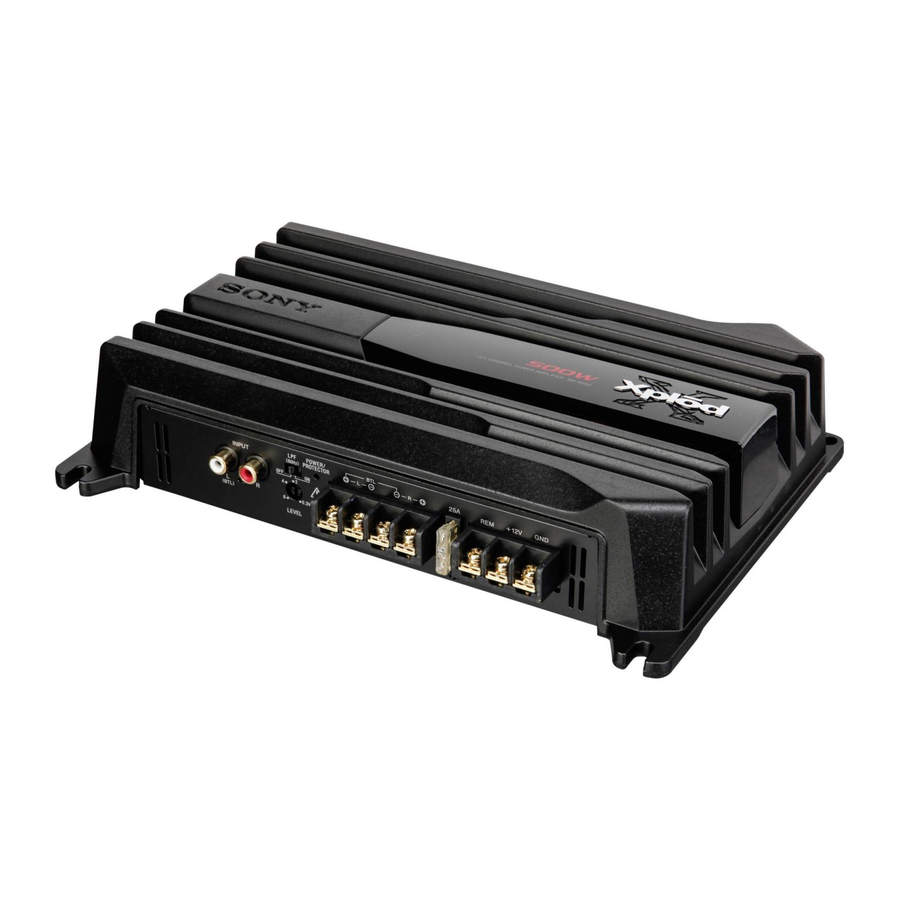
Location and Function of Controls

- LEVEL adjustment control
The input level can be adjusted with this control. Turn it in the clockwise direction when the output level of the car audio unit seems low. - LPF switch
When the LPF switch is set to ON, the Low-pass filter (80 Hz) is effective. - POWER/PROTECTOR indicator
Lights up in green during operation. When the PROTECTOR is activated the indicator will change from green to red. When the PROTECTOR is activated refer to the Troubleshooting Guide.
Precautions
- Avoid installing the unit in areas subject to:
* Protection circuit
This amplifier is provided with a protection circuit that operates in the following cases:
The colour of the POWER/PROTECTOR indicator will change from green to red, and the unit will shut down.
If this happens, turn off the connected equipment, take out the cassette tape or disc, and determine the cause of the malfunction. If the amplifier has overheated, wait until the unit cools down before use.
Fuse Replacement
If the fuse blows, check the power connection and replace the fuse. If the fuse blows again after replacement, there may be an internal malfunction. In such a case, consult your nearest Sony dealer.
Warning
When replacing the fuse, be sure to use one matching the amperage stated above the fuse holder. Never use a fuse with an amperage rating exceeding the one supplied with the unit as this could damage the unit.

If you have any questions or problems concerning your unit that are not covered in this manual, please consult your nearest Sony dealer.
Connections
Cautions
- Do not connect the
![]() terminal of the speaker system to the car chassis, and do not connect the
terminal of the speaker system to the car chassis, and do not connect the ![]() terminal of the right speaker with that of the left speaker.
terminal of the right speaker with that of the left speaker.
 terminal of the speaker system to the car chassis, and do not connect the
 Parts for Installation and Connections

Installation
Before Installation
Mount the unit
First, place the unit where you plan to install it, and mark the positions of the 4 screw holes on the mounting board (not supplied). Then drill a 3 mm pilot hole at each mark and mount the unit onto the board with the supplied mounting screws. The mounting screws are all 20 mm long, so make sure that the mounting board is thicker than 20 mm.

Power connections
Make the terminal connections
Pass the wires through the cap, connect the wires, then cover the terminals with the cap.

Note
When you tighten the screw, be careful not to apply too much torque* as doing so may damage the screw.
* The torque value should be less than 1 N•m.

Make the power connections

*1 If you have the factory original or some other car audio unit without a remote output for the amplifier, connect the remote input terminal (REMOTE) to the accessory power supply. In High level input connection, car audio unit can also be activated without need for REMOTE connection. However, this function is not guaranteed for all car audio units.
Notes on the power supply
- Be sure to connect the ground wire of the unit securely to a metal point of the car. A loose connection may cause a malfunction of the amplifier.
- Make sure that the vehicle's battery wires connected to the vehicle (ground to chassis)*2 are of a wire gauge at least equal to that of the main power wire connected from the battery to the amplifier.
- During full-power operation, a current of more than 25 A will run through the system. Therefore, make sure that the wires to be connected to the +12V and GND terminals of this unit are at least 14-Gauge (AWG-14) or have a sectional area of more than 2 mm2.
Input Connections
For details on input connections, see below

Line Input Connection (with Speaker Connection)

Line Input Connection (with Speaker Connection)

High Level Input Connection (with Speaker Connection)

High Level Input Connection (with Speaker Connection)

High Level Input Connection (with Speaker Connection)
Speaker Connections
Turn on or off the LPF switch at the unit rear. For details on speaker connections, see below

2-Speaker System (with Input Connection)

Subwoofer (with Input Connection)
Note
If you wish to use a subwoofer as the monaural speaker, connect the speaker as illustrated above. The output signals to the subwoofer will be the combination of both right and left output signals.

1-Speaker System (with Input Connection)
Note
Make sure that the line output from the car audio unit is connected to the jack marked "L (BTL)" on the unit.

Dual Mode System (with a Bridged Subwoofer)
Table of crossover values for 6 dB/ octave (4 Ω) (Speaker Connections)
| Crossover Frequency unit: Hz | L (coil)* unit: mH | C1/C2 (capacitor)* unit: µF |
| 50 | 12.7 | 800 |
| 80 | 8.2 | 500 |
| 100 | 6.2 | 400 |
| 130 | 4.7 | 300 |
| 150 | 4.2 | 270 |
| 200 | 3.3 | 200 |
| 260 | 2.4 | 150 |
| 400 | 1.6 | 100 |
| 600 | 1.0 | 68 |
| 800 | 0.8 | 50 |
| 1,000 | 0.6 | 39 |
* Not supplied
Notes
Troubleshooting Guide
The following checklist will assist in the correction of most problems which you may encounter with your unit.
Before going through the checklist below, refer to the connection and operating procedures.
The POWER/PROTECTOR indicator does not light up
- The voltage going into the remote terminal is too low.
The POWER/PROTECTOR indicator will change from green to red
The unit becomes abnormally hot
The sound is interrupted
Alternator noise is heard
The sound is muffled
The sound is too low
- The LEVEL adjustment control is not appropriate.
Turn the LEVEL adjustment control in the clockwise direction.

Documents / Resources
References
Download manual
Here you can download full pdf version of manual, it may contain additional safety instructions, warranty information, FCC rules, etc.


